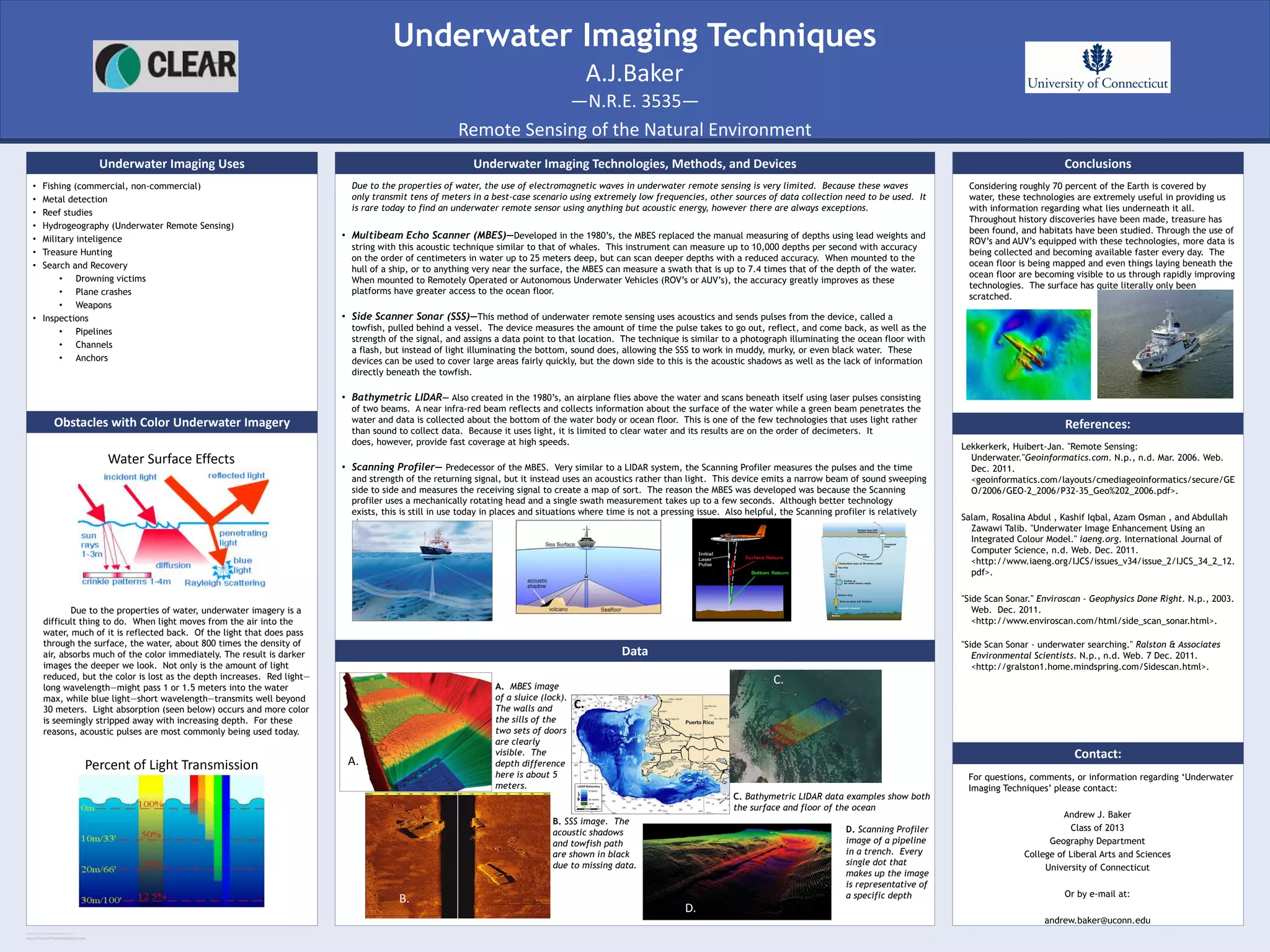
RESEARCH POSTER PRESENTATION DESIGN © 2011
www.PosterPresentations.com
• Fishing (commercial, non-commercial)
• Metal detection
• Reef studies
• Hydrogeography (Underwater Remote Sensing)
• Military inteligence
• Treasure Hunting
• Search and Recovery
• Drowning victims
• Plane crashes
• Weapons
• Inspections
• Pipelines
• Channels
• Anchors
Underwater Imaging Uses
Due to the properties of water, underwater imagery is a
difficult thing to do. When light moves from the air into the
water, much of it is reflected back. Of the light that does pass
through the surface, the water, about 800 times the density of
air, absorbs much of the color immediately. The result is darker
images the deeper we look. Not only is the amount of light
reduced, but the color is lost as the depth increases. Red light—
long wavelength—might pass 1 or 1.5 meters into the water
max, while blue light—short wavelength—transmits well beyond
30 meters. Light absorption (seen below) occurs and more color
is seemingly stripped away with increasing depth. For these
reasons, acoustic pulses are most commonly being used today.
Obstacles with Color Underwater Imagery
Due to the properties of water, the use of electromagnetic waves in underwater remote sensing is very limited. Because these waves
only transmit tens of meters in a best-case scenario using extremely low frequencies, other sources of data collection need to be used. It
is rare today to find an underwater remote sensor using anything but acoustic energy, however there are always exceptions.
• Multibeam Echo Scanner (MBES)—Developed in the 1980’s, the MBES replaced the manual measuring of depths using lead weights and
string with this acoustic technique similar to that of whales. This instrument can measure up to 10,000 depths per second with accuracy
on the order of centimeters in water up to 25 meters deep, but can scan deeper depths with a reduced accuracy. When mounted to the
hull of a ship, or to anything very near the surface, the MBES can measure a swath that is up to 7.4 times that of the depth of the water.
When mounted to Remotely Operated or Autonomous Underwater Vehicles (ROV’s or AUV’s), the accuracy greatly improves as these
platforms have greater access to the ocean floor.
• Side Scanner Sonar (SSS)—This method of underwater remote sensing uses acoustics and sends pulses from the device, called a
towfish, pulled behind a vessel. The device measures the amount of time the pulse takes to go out, reflect, and come back, as well as the
strength of the signal, and assigns a data point to that location. The technique is similar to a photograph illuminating the ocean floor with
a flash, but instead of light illuminating the bottom, sound does, allowing the SSS to work in muddy, murky, or even black water. These
devices can be used to cover large areas fairly quickly, but the down side to this is the acoustic shadows as well as the lack of information
directly beneath the towfish.
• Bathymetric LIDAR— Also created in the 1980’s, an airplane flies above the water and scans beneath itself using laser pulses consisting
of two beams. A near infra-red beam reflects and collects information about the surface of the water while a green beam penetrates the
water and data is collected about the bottom of the water body or ocean floor. This is one of the few technologies that uses light rather
than sound to collect data. Because it uses light, it is limited to clear water and its results are on the order of decimeters. It
does, however, provide fast coverage at high speeds.
• Scanning Profiler— Predecessor of the MBES. Very similar to a LIDAR system, the Scanning Profiler measures the pulses and the time
and strength of the returning signal, but it instead uses an acoustics rather than light. This device emits a narrow beam of sound sweeping
side to side and measures the receiving signal to create a map of sort. The reason the MBES was developed was because the Scanning
profiler uses a mechanically rotating head and a single swath measurement takes up to a few seconds. Although better technology
exists, this is still in use today in places and situations where time is not a pressing issue. Also helpful, the Scanning profiler is relatively
cheap.
Underwater Imaging Technologies, Methods, and Devices
Data
Conclusions
Considering roughly 70 percent of the Earth is covered by
water, these technologies are extremely useful in providing us
with information regarding what lies underneath it all.
Throughout history discoveries have been made, treasure has
been found, and habitats have been studied. Through the use of
ROV’s and AUV’s equipped with these technologies, more data is
being collected and becoming available faster every day. The
ocean floor is being mapped and even things laying beneath the
ocean floor are becoming visible to us through rapidly improving
technologies. The surface has quite literally only been
scratched.
References:
Lekkerkerk, Huibert-Jan. "Remote Sensing:
Underwater."Geoinformatics.com. N.p., n.d. Mar. 2006. Web.
Dec. 2011.
<geoinformatics.com/layouts/cmediageoinformatics/secure/GE
O/2006/GEO-2_2006/P32-35_Geo%202_2006.pdf>.
Salam, Rosalina Abdul , Kashif Iqbal, Azam Osman , and Abdullah
Zawawi Talib. "Underwater Image Enhancement Using an
Integrated Colour Model." iaeng.org. International Journal of
Computer Science, n.d. Web. Dec. 2011.
<http://www.iaeng.org/IJCS/issues_v34/issue_2/IJCS_34_2_12.
pdf>.
"Side Scan Sonar." Enviroscan - Geophysics Done Right. N.p., 2003.
Web. Dec. 2011.
<http://www.enviroscan.com/html/side_scan_sonar.html>.
"Side Scan Sonar - underwater searching." Ralston & Associates
Environmental Scientists. N.p., n.d. Web. 7 Dec. 2011.
<http://gralston1.home.mindspring.com/Sidescan.html>.
Contact:
For questions, comments, or information regarding ‘Underwater
Imaging Techniques’ please contact:
Andrew J. Baker
Class of 2013
Geography Department
College of Liberal Arts and Sciences
University of Connecticut
Or by e-mail at:
andrew.baker@uconn.edu
Underwater Imaging Techniques
—N.R.E. 3535—
Remote Sensing of the Natural Environment
A.J.Baker
Water Surface Effects
Percent of Light Transmission A.
B.
C.
C.
D.
A. MBES image
of a sluice (lock).
The walls and
the sills of the
two sets of doors
are clearly
visible. The
depth difference
here is about 5
meters.
B. SSS image. The
acoustic shadows
and towfish path
are shown in black
due to missing data.
C.
C. Bathymetric LIDAR data examples show both
the surface and floor of the ocean
D. Scanning Profiler
image of a pipeline
in a trench. Every
single dot that
makes up the image
is representative of
a specific depth

Underwater imaging

  • 1.
    RESEARCH POSTER PRESENTATIONDESIGN © 2011 www.PosterPresentations.com • Fishing (commercial, non-commercial) • Metal detection • Reef studies • Hydrogeography (Underwater Remote Sensing) • Military inteligence • Treasure Hunting • Search and Recovery • Drowning victims • Plane crashes • Weapons • Inspections • Pipelines • Channels • Anchors Underwater Imaging Uses Due to the properties of water, underwater imagery is a difficult thing to do. When light moves from the air into the water, much of it is reflected back. Of the light that does pass through the surface, the water, about 800 times the density of air, absorbs much of the color immediately. The result is darker images the deeper we look. Not only is the amount of light reduced, but the color is lost as the depth increases. Red light— long wavelength—might pass 1 or 1.5 meters into the water max, while blue light—short wavelength—transmits well beyond 30 meters. Light absorption (seen below) occurs and more color is seemingly stripped away with increasing depth. For these reasons, acoustic pulses are most commonly being used today. Obstacles with Color Underwater Imagery Due to the properties of water, the use of electromagnetic waves in underwater remote sensing is very limited. Because these waves only transmit tens of meters in a best-case scenario using extremely low frequencies, other sources of data collection need to be used. It is rare today to find an underwater remote sensor using anything but acoustic energy, however there are always exceptions. • Multibeam Echo Scanner (MBES)—Developed in the 1980’s, the MBES replaced the manual measuring of depths using lead weights and string with this acoustic technique similar to that of whales. This instrument can measure up to 10,000 depths per second with accuracy on the order of centimeters in water up to 25 meters deep, but can scan deeper depths with a reduced accuracy. When mounted to the hull of a ship, or to anything very near the surface, the MBES can measure a swath that is up to 7.4 times that of the depth of the water. When mounted to Remotely Operated or Autonomous Underwater Vehicles (ROV’s or AUV’s), the accuracy greatly improves as these platforms have greater access to the ocean floor. • Side Scanner Sonar (SSS)—This method of underwater remote sensing uses acoustics and sends pulses from the device, called a towfish, pulled behind a vessel. The device measures the amount of time the pulse takes to go out, reflect, and come back, as well as the strength of the signal, and assigns a data point to that location. The technique is similar to a photograph illuminating the ocean floor with a flash, but instead of light illuminating the bottom, sound does, allowing the SSS to work in muddy, murky, or even black water. These devices can be used to cover large areas fairly quickly, but the down side to this is the acoustic shadows as well as the lack of information directly beneath the towfish. • Bathymetric LIDAR— Also created in the 1980’s, an airplane flies above the water and scans beneath itself using laser pulses consisting of two beams. A near infra-red beam reflects and collects information about the surface of the water while a green beam penetrates the water and data is collected about the bottom of the water body or ocean floor. This is one of the few technologies that uses light rather than sound to collect data. Because it uses light, it is limited to clear water and its results are on the order of decimeters. It does, however, provide fast coverage at high speeds. • Scanning Profiler— Predecessor of the MBES. Very similar to a LIDAR system, the Scanning Profiler measures the pulses and the time and strength of the returning signal, but it instead uses an acoustics rather than light. This device emits a narrow beam of sound sweeping side to side and measures the receiving signal to create a map of sort. The reason the MBES was developed was because the Scanning profiler uses a mechanically rotating head and a single swath measurement takes up to a few seconds. Although better technology exists, this is still in use today in places and situations where time is not a pressing issue. Also helpful, the Scanning profiler is relatively cheap. Underwater Imaging Technologies, Methods, and Devices Data Conclusions Considering roughly 70 percent of the Earth is covered by water, these technologies are extremely useful in providing us with information regarding what lies underneath it all. Throughout history discoveries have been made, treasure has been found, and habitats have been studied. Through the use of ROV’s and AUV’s equipped with these technologies, more data is being collected and becoming available faster every day. The ocean floor is being mapped and even things laying beneath the ocean floor are becoming visible to us through rapidly improving technologies. The surface has quite literally only been scratched. References: Lekkerkerk, Huibert-Jan. "Remote Sensing: Underwater."Geoinformatics.com. N.p., n.d. Mar. 2006. Web. Dec. 2011. <geoinformatics.com/layouts/cmediageoinformatics/secure/GE O/2006/GEO-2_2006/P32-35_Geo%202_2006.pdf>. Salam, Rosalina Abdul , Kashif Iqbal, Azam Osman , and Abdullah Zawawi Talib. "Underwater Image Enhancement Using an Integrated Colour Model." iaeng.org. International Journal of Computer Science, n.d. Web. Dec. 2011. <http://www.iaeng.org/IJCS/issues_v34/issue_2/IJCS_34_2_12. pdf>. "Side Scan Sonar." Enviroscan - Geophysics Done Right. N.p., 2003. Web. Dec. 2011. <http://www.enviroscan.com/html/side_scan_sonar.html>. "Side Scan Sonar - underwater searching." Ralston & Associates Environmental Scientists. N.p., n.d. Web. 7 Dec. 2011. <http://gralston1.home.mindspring.com/Sidescan.html>. Contact: For questions, comments, or information regarding ‘Underwater Imaging Techniques’ please contact: Andrew J. Baker Class of 2013 Geography Department College of Liberal Arts and Sciences University of Connecticut Or by e-mail at: andrew.baker@uconn.edu Underwater Imaging Techniques —N.R.E. 3535— Remote Sensing of the Natural Environment A.J.Baker Water Surface Effects Percent of Light Transmission A. B. C. C. D. A. MBES image of a sluice (lock). The walls and the sills of the two sets of doors are clearly visible. The depth difference here is about 5 meters. B. SSS image. The acoustic shadows and towfish path are shown in black due to missing data. C. C. Bathymetric LIDAR data examples show both the surface and floor of the ocean D. Scanning Profiler image of a pipeline in a trench. Every single dot that makes up the image is representative of a specific depth