Download as PDF, PPTX


![Diver visibility range & attenuation
ln CL From Radiative Transfer Theory,
visibility range ( m ), V = − • Priesendorfer (1976)
c • Duntley (1963)
CL contrast detection limit for human being
c optical beam attenuation coefficient (m-1)
4.8
V=
[1.18c(650) + 0.081]
Accuracy better than 10%
Backscattering is NOT a
good proxy for visibility
Zaneveld and Pegau (2003)](https://image.slidesharecdn.com/navalapplicationsofoceanopticscoursesampler-120510153650-phpapp02/85/Ocean-Optics-Fundamentals-Naval-Applications-Technical-Training-Short-Course-Sampler-26-320.jpg)
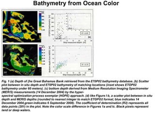
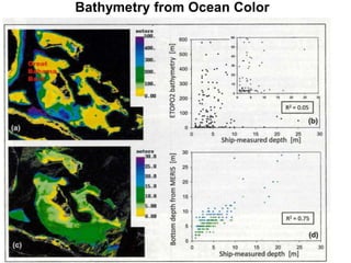
![Bathymetry from Ocean Color
• Knowledge of ocean bathymetry is important for navigation & for
scientific studies of the ocean's volume, ecology, and circulation, all
of which are related to Earth's climate.
• In coastal regions detailed bathymetric maps are critical for storm
surge modeling, marine power plant planning, understanding of
ecosystem connectivity, coastal management, and change analyses.
• Because ocean areas are enormously large and ship surveys have
limited coverage, adequate bathymetric data are still lacking
throughout the global ocean.
• Satellite altimetry can produce reasonable estimates of bathymetry
for the deep ocean [Sandwell et al., 2003, 2006], but the spatial
resolution is very coarse (∼6–9 kilometers) and can be highly
inaccurate in shallow waters, where gravitational effects are small.
• Depths retrieved from the ETOPO2 bathymetry database for the Great
Bahama Bank are seriously in error when compared with ship
surveys & no statistical correlation was found between the two
• Determining a higher-spatial-resolution (e.g., 300-meter) bathymetry
of this region with ship surveys would require ~ 4 years of nonstop
effort.
Ref: Lee, Z., et.al., "Global Shallow-Water Bathymetry From Satellite Ocean Color Data,” EOS, Transactions American
Geophysical Union, VOL. 91, NO. 46, P. 429, 2010, doi:10.1029/2010EO460002](https://image.slidesharecdn.com/navalapplicationsofoceanopticscoursesampler-120510153650-phpapp02/85/Ocean-Optics-Fundamentals-Naval-Applications-Technical-Training-Short-Course-Sampler-39-320.jpg)


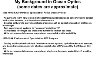
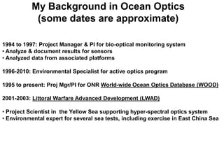
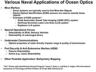
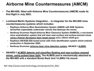
The document provides background on Jeffrey Smart's experience in ocean optics from 1988 to present. It discusses his work on various naval projects involving the use of optical sensors to measure water clarity and the applications of ocean optics for mine warfare, port security, underwater communications, and submarine detection. Specific sensor systems are also described, such as the Airborne Laser Mine Detection System.


