This project is based on transformation of data like text, voice, audio and image through underwater using visible light. This is major application in military like navy and submarines, scientific community for underwater research, flood detection, climatic changes , oceanography and more . The cost of this budget around 15k to 17k.
Topic on Underwater Communication which includes both underwater wireless and wired communication . A full detailed overview about the topic has been given. Pictures are given to visualize the topic in better way. Covers a major potion like Hydrophones and SONAR. Can be presented as a seminar topic as well .
Underwater Wireless Communication is the wireless communication in which acoustic signals (waves) carry digital information through an underwater channel.
Underwater acoustic communication is a technique of sending and receiving message below water.[1] There are several ways of employing such communication but the most common is using hydrophones. Under water communication is difficult due to factors like multi-path propagation, time variations of the channel, small available bandwidth and strong signal attenuation, especially over long ranges. In underwater communication there are low data rates compared to terrestrial communication, since underwater communication uses acoustic waves instead of electromagnetic waves.
While wireless communication technology today has become part of our daily life, the
idea of wireless undersea communications may still seem far-fetched. However, research has
been active for over a decade on designing the methods for wireless information transmission
underwater. Human knowledge and understanding of the world’s oceans, which constitute
the major part of our planet, rests on our ability to collect information from remote undersea
locations.
The major discoveries of the past decades, such as the remains of Titanic, or the hydrothermal
vents at bottom of deep ocean, were made using cabled submersibles. Although such
systems remain indispensable if high-speed communication link is to exists between the
remote end and the surface, it is natural to wonder what one could accomplish without the
burden (and cost) of heavy cables.
Hence the motivation, and interest in wireless underwater communications. Together with
sensor technology and vehicular technology, wireless communications will enable new
applications ranging from environmental monitoring to gathering of oceanographic data,
marine archaeology, and search and rescue missions.
Underwater wireless communication networks (UWCNs) consist of sensors and autonomous underwater vehicles (AUVs) that interact, coordinate and share information with each other to carry out sensing and monitoring functions.
In this i tried to explain about under water communication.
Introduction of underwater communication.
Problem due to Multipath Propagation
Techniques used for underwater communication
1. Single Carrier Systems
2. MCM Techniques
3. Space-Time Modulation Techniques
Applications
Limitations
Conclusion
MicroStrip Antenna
Introduction .
Micro-Strip Antennas Types .
Micro-Strip Antennas Shapes .
Types of Substrates (Dielectric Media) .
Comparison of various types of flat profile printed antennas .
Advantages & DisAdvantages of MSAs .
Applications of MSAs .
Radiation patterns of MSAs .
How to Optimizing the Substrate Properties for Increased Bandwidth ?
Comparing the different feed techniques .
IBOC (In Band On Channel) Technology for DIgital Radio.Ashik Ask
The engineering world has been working on the development and evaluation of IBOC transmission for some time. The NRSC began evaluation proceedings of general DAB systems in 1995. After the proponents merged into one, Ibiquity was left in the running for potential adoption. In the fall of 2001,the NRSC issued a report on Ibiquity's FM IBOC. This comprehensive report runs 62 pages of engineering material plus 13 appendices. All of the system with its blend-to analog operation as signals levels changes. The application of the FM IBOC has been studied by the NRSC and appears to be understood and accepted by radio engineers. AM IBOC has recently been studied by an NRSC working group as prelude to its adoption for general broadcast use .Its was presented during the NAB convention in April. The FM report covers eight areas of vital performance concerns to the broadcaster and listener alike .If all of these concerns can be met as successfully by AM IBOC, and the receiver manufactures rally to develop and produce the necessary receiving equipment. The evaluated FM concerns were audio quality, service area, acquisition performance, durability, auxiliary data capacity, and behavior as signal degrades stereo separation and flexibility.
The FM report paid strong attention to the use of SCA services on FM IBOC. About half of all the operating FM stations employ one or more SCAs for reading for the blind or similar services. Before going to the description of FM IBOC system, it is important to discuss the basic principles of digital radio, and IBOCtechnology.
Tutorial on Wireless Communications and Networking with Drones and Unmanned A...saadwalid
A comprehensive tutorial on how drones and unmanned aerial vehicles (UAVs) can be used for wireless communications and networking purpose. The tutorial studies all aspects of drones from performance analysis to deployment, resource management, and security.
Design of Underwater wireless optical/acoustic link for reduction of back-sca...theijes
Underwater communication plays a significant role in the study of climate change through ocean monitoring and associated sensor networks. It is severely limited when compared to free space communication because water is essentially opaque to electromagnetic radiation except in the visible band. Even in the visible band, light penetrates only a few hundred meters in the clearest waters and much less in turbid waters due to the presence of suspended sediment or high concentrations of marine life. Consequently, acoustic techniques are been used for underwater communication systems which is relatively mature and robust. Acoustic systems are capable of long range communication. But traditional underwater acoustic communications cannot provide high enough data rates to enable monitoring technology. Optical wireless communications, centred around blue-green wavelengths, are being used as an alternative. Here a hybrid design is being introduced using an optical/acoustic link to reduce back scattering of transmitted light.
An implementation of_partial_transmit_seWaleed Raza
In this article we research about underwater
acoustics transceivers. As Underwater acoustic transceivers
consume more power than Radio frequency transceivers.
The techniques which are being utilized in radio frequency
cannot be implemented directly in underwater acoustic
system it needs to be re investigated to design new methods.
To achieve reliable acoustic data transmission new
techniques should be achieved or the traditional
Orthogonal frequency divisional multiplexing techniques
should be revised. The power consumption also relies upon
underwater acoustic signal propagation and transmission
distances. Several underwater acoustic applications require
long-term monitoring of the sea. For the battery powered
modems, it becomes very serious problem. By designing an
Energy efficient OFDM Communication system we can
solve this problem. We study about peak to average power
ratio in an Orthogonal frequency divisional multiplexing
system by reducing the major draw-back of OFDM system.
The PAPR reduction utilized in this paper is Partial
Transmit Sequences for underwater acoustic OFDM
communication system which has lesser complexity. The
results have provided better performance in underwater
acoustic OFDM communication system.
Analysis of CoDBR and CEEDBR protocols in underwater wireless sensor networksbijcicnjournal
Underwater wireless sensor networks (UWSNs) are essential for doing any type of task underwater. Huge broadcast lag, great error degree, small bandwidth, and restricted energy in Underwater Sensor Networks interest concentration of utmost investigators. In UWSNs, the efficient use of energy is one of the main problems, as the substitution of energy sources in this kind of location is extremely costly. UWSNs are utilized in many fields, like measuring pollution, issuing tsunami cautions, conducting offshore surveys, and strategic tracing. For numerous functions, the efficacy and dependability of network regarding prominent operation, energy preservation, small bit error rate, and decreased interruption are fundamental. Nevertheless, UWSN’s exclusive features like small bandwidth accessibility, large interruptions in broadcast, very vivacious network topology, and extreme possibility of error present numerous problems in the growth of effective and dependable communication procedures. As opposed to current deepness-based routing techniques, we are focusing on CoDBR (Cooperative Depthbased Routing) and CEEDBR (Cooperative Energy Efficient Depth-based Routing) procedures to improve network lifespan, energy efficacy, and amount.
Analysis of CODBR and CEEDBR Protocols in Underwater Wireless Sensor Networksbijcicnjounal
UWSNs (underwater wireless sensor networks) are essential for doing any type of task underwater. Huge broadcast lag, great error degree, small bandwidth, and restricted energy in Underwater Sensor Networks interest concentration of utmost investigators. In UWSNs, the efficient use of energy is one of the main problems, as the substitution of energy sources in this kind of location is extremely costly. UWSNs are utilized in many fields, like measuring pollution, issuing tsunami cautions, conducting offshore surveys, and strategic tracing. For numerous functions, the efficacy and dependability of network regarding prominent operation, energy preservation, small bit error rate, and decreased interruption are fundamental. Nevertheless, UWSN’s exclusive features like small bandwidth accessibility, large interruptions in broadcast, very vivacious network topology, and extreme possibility of error present numerous problems in the growth of effective and dependable communication procedures. As opposed to current deepness-based routing techniques, we are focusing on CoDBR (Cooperative Depth-based Routing) and CEEDBR (Cooperative Energy Efficient Depth-based Routing) procedures to improve network lifespan, energy efficacy, and amount.
Today’s majority of data technique uses Radio Spectrum. But the major drawback of data
technique using radio spectrum is that it is very congested and the demand for wireless data
double each year. Every one, it seems want to use wireless data but the capacity is drying up.
Light –Fidelity is the transmission of data through illumination .It comprises of sending data
through a Light Emitting Diode which varies in intensity faster than human eye can follow .It
uses the fact that light travels at a such a high speed which is faster than human eye to catch.
Therefore when we vary the intensity of light emitting source it become impossible for the
humans to catch that sensation. It leads to very high speed data transmission, which is for
superior to current technologies.
Development of an FHMA-based Underwater Acoustic Communications System for Mu...Waqas Tariq
This paper describes the design of an underwater acoustic communications system for multiple underwater vehicles, based on frequency-hopping multiple-access (FHMA) and tamed spread-spectrum communications. The system makes used of the tamed spread-spectrum method, frequency hopping, 4FSK, and a rake receiver. In order to make the system more practical, the underwater channel and the effect of the number of users on the bit error ratio (BER) are also taken into account. Since the necessary proving experiments are not easily conducted in the ocean, a platform is developed that uses the sound card of a computer, combined with a sound box and microphone, to transduce energy for acoustic communications. Simulated and experimental results indicate that this system could provide reliable underwater communications between multiple underwater vehicles.
Free-Space Optical Networking Using the Spectrum of Visible LightIJTET Journal
Radio frequency technology suffers from limited bandwidth and electromagnetic interference. The recent
developments in solid-state Light Emitting Diode (LED) materials and devices are driving resurgence into the use of Free-Space Optical (FSO) wireless communication. LED-based network transceivers have a variety of competitive advantages over RF
including high bandwidth density, security, energy consumption, and aesthetics. They also use a highly reusable unregulated part of the spectrum (visible light). Many opportunities exist to exploit low-cost nature of LEDs and lighting units for widespread deployment of optical communication. The prime focus is to reducing cost, and for that, we have to make appropriate selection
of system’s components, e.g. modulation, coding, filtering. The objective is to describe the viability of an optical free-space visible light transceiver as a basis for indoor wireless networking and to achieve acceptable bit error rate (BER) performance for indoor use, with a low cost system.
Fog attenuation penalty analysis in terrestrial optical wireless communicatio...nooriasukmaningtyas
In metropolitan communication infrastructures a revolutionary technique is emerge known as terrestrial optical wireless communication (OWC), which makes a high-rise building connection is possible. Even with this solution, there are many other problems like the influence of haze and fog in the propagation channel which obstruct and scatter OWC propagation light and consequently led to a big attenuation, due to propagate in temporal, angular and spatial of the light signal. Not to mention the minimum visibility that discourages the implementation of the pointing errors (PE) and tracking system. This present work aims to analyze the interrelation between multiple scattering (dense fog, heavy fog, light fog, heavy haze and light haze) and receiver PE under modified duo-binary return-to-zero (MDRZ) system. We found that PE caused by beam swag is the main controlling factor and industriously minimize the link margin, signal-to-noise ratio (SNR), and raise the bit error rate (BER) when there is an increasing the turbulence strength and the track length. We recommended to guarantee transmitter– receiver alignment by installing a variable field of view (FOV) receiver (a tracking system) to overcome the scattering impact of the fog that make render urban laser communication effective in the presence of PE.
An energy aware scheme for layered chain in underwater wireless sensor networ...IJECEIAES
Extending the network lifetime is a very challenging problem that needs to be taken into account during routing data in wireless sensor networks in general and particularly in underwater wireless sensor networks (UWSN). For this purpose, the present paper proposes a multilayer chain based on genetic algorithm routing (MCGA) for routing data from nodes to the sink. This algorithm consists to create a limited number of local chains constructed by using genetic algorithm in order to obtain the shortest path between nodes; furthermore, a leader node (LN) is elected in each chain followed by constructing a global chain containing LNs. The selection of the LN in the closest chain to the sink is as follows: Initially, the closest node to sink is elected LN in this latter because all nodes have initially the same energy value; then the future selection of the LN is based on the residual energy of the nodes. LNs in the other chains are selected based on the proximity to the previous LNs. Data transmission is performed in two steps: intra-chain transmission and inter-chain transmission. Furthermore, MCGA is simulated for different scenarios of mobility and density of nodes in the networks. The performance evaluation of the proposed technique shows a considerable reduction in terms of energy consumption and network lifespan.
CFD Simulation of By-pass Flow in a HRSG module by R&R Consult.pptxR&R Consult
CFD analysis is incredibly effective at solving mysteries and improving the performance of complex systems!
Here's a great example: At a large natural gas-fired power plant, where they use waste heat to generate steam and energy, they were puzzled that their boiler wasn't producing as much steam as expected.
R&R and Tetra Engineering Group Inc. were asked to solve the issue with reduced steam production.
An inspection had shown that a significant amount of hot flue gas was bypassing the boiler tubes, where the heat was supposed to be transferred.
R&R Consult conducted a CFD analysis, which revealed that 6.3% of the flue gas was bypassing the boiler tubes without transferring heat. The analysis also showed that the flue gas was instead being directed along the sides of the boiler and between the modules that were supposed to capture the heat. This was the cause of the reduced performance.
Based on our results, Tetra Engineering installed covering plates to reduce the bypass flow. This improved the boiler's performance and increased electricity production.
It is always satisfying when we can help solve complex challenges like this. Do your systems also need a check-up or optimization? Give us a call!
Work done in cooperation with James Malloy and David Moelling from Tetra Engineering.
More examples of our work https://www.r-r-consult.dk/en/cases-en/
Saudi Arabia stands as a titan in the global energy landscape, renowned for its abundant oil and gas resources. It's the largest exporter of petroleum and holds some of the world's most significant reserves. Let's delve into the top 10 oil and gas projects shaping Saudi Arabia's energy future in 2024.
Cosmetic shop management system project report.pdfKamal Acharya
Buying new cosmetic products is difficult. It can even be scary for those who have sensitive skin and are prone to skin trouble. The information needed to alleviate this problem is on the back of each product, but it's thought to interpret those ingredient lists unless you have a background in chemistry.
Instead of buying and hoping for the best, we can use data science to help us predict which products may be good fits for us. It includes various function programs to do the above mentioned tasks.
Data file handling has been effectively used in the program.
The automated cosmetic shop management system should deal with the automation of general workflow and administration process of the shop. The main processes of the system focus on customer's request where the system is able to search the most appropriate products and deliver it to the customers. It should help the employees to quickly identify the list of cosmetic product that have reached the minimum quantity and also keep a track of expired date for each cosmetic product. It should help the employees to find the rack number in which the product is placed.It is also Faster and more efficient way.
Overview of the fundamental roles in Hydropower generation and the components involved in wider Electrical Engineering.
This paper presents the design and construction of hydroelectric dams from the hydrologist’s survey of the valley before construction, all aspects and involved disciplines, fluid dynamics, structural engineering, generation and mains frequency regulation to the very transmission of power through the network in the United Kingdom.
Author: Robbie Edward Sayers
Collaborators and co editors: Charlie Sims and Connor Healey.
(C) 2024 Robbie E. Sayers
About
Indigenized remote control interface card suitable for MAFI system CCR equipment. Compatible for IDM8000 CCR. Backplane mounted serial and TCP/Ethernet communication module for CCR remote access. IDM 8000 CCR remote control on serial and TCP protocol.
• Remote control: Parallel or serial interface.
• Compatible with MAFI CCR system.
• Compatible with IDM8000 CCR.
• Compatible with Backplane mount serial communication.
• Compatible with commercial and Defence aviation CCR system.
• Remote control system for accessing CCR and allied system over serial or TCP.
• Indigenized local Support/presence in India.
• Easy in configuration using DIP switches.
Technical Specifications
Indigenized remote control interface card suitable for MAFI system CCR equipment. Compatible for IDM8000 CCR. Backplane mounted serial and TCP/Ethernet communication module for CCR remote access. IDM 8000 CCR remote control on serial and TCP protocol.
Key Features
Indigenized remote control interface card suitable for MAFI system CCR equipment. Compatible for IDM8000 CCR. Backplane mounted serial and TCP/Ethernet communication module for CCR remote access. IDM 8000 CCR remote control on serial and TCP protocol.
• Remote control: Parallel or serial interface
• Compatible with MAFI CCR system
• Copatiable with IDM8000 CCR
• Compatible with Backplane mount serial communication.
• Compatible with commercial and Defence aviation CCR system.
• Remote control system for accessing CCR and allied system over serial or TCP.
• Indigenized local Support/presence in India.
Application
• Remote control: Parallel or serial interface.
• Compatible with MAFI CCR system.
• Compatible with IDM8000 CCR.
• Compatible with Backplane mount serial communication.
• Compatible with commercial and Defence aviation CCR system.
• Remote control system for accessing CCR and allied system over serial or TCP.
• Indigenized local Support/presence in India.
• Easy in configuration using DIP switches.
Final project report on grocery store management system..pdfKamal Acharya
In today’s fast-changing business environment, it’s extremely important to be able to respond to client needs in the most effective and timely manner. If your customers wish to see your business online and have instant access to your products or services.
Online Grocery Store is an e-commerce website, which retails various grocery products. This project allows viewing various products available enables registered users to purchase desired products instantly using Paytm, UPI payment processor (Instant Pay) and also can place order by using Cash on Delivery (Pay Later) option. This project provides an easy access to Administrators and Managers to view orders placed using Pay Later and Instant Pay options.
In order to develop an e-commerce website, a number of Technologies must be studied and understood. These include multi-tiered architecture, server and client-side scripting techniques, implementation technologies, programming language (such as PHP, HTML, CSS, JavaScript) and MySQL relational databases. This is a project with the objective to develop a basic website where a consumer is provided with a shopping cart website and also to know about the technologies used to develop such a website.
This document will discuss each of the underlying technologies to create and implement an e- commerce website.
Water scarcity is the lack of fresh water resources to meet the standard water demand. There are two type of water scarcity. One is physical. The other is economic water scarcity.
Implementation of Optical wireless communication through underwater channel
1. Implementation of Optical Wireless Communication through Underwater Channel
Dept. of ECE Page No 1
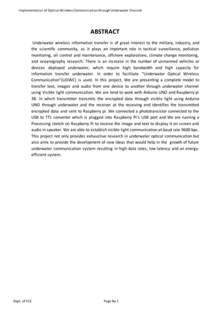
ABSTRACT
Underwater wireless information transfer is of great interest to the military, industry, and
the scientific community, as it plays an important role in tactical surveillance, pollution
monitoring, oil control and maintenance, offshore explorations, climate change monitoring,
and oceanography research. There is an increase in the number of unmanned vehicles or
devices deployed underwater, which require high bandwidth and high capacity for
information transfer underwater. In order to facilitate “Underwater Optical Wireless
Communication”(UOWC) is used. In this project, We are presenting a complete model to
transfer text, images and audio from one device to another through underwater channel
using Visible light communication. We are tend to work with Arduino UNO and Raspberry pi
3B. In which transmitter transmits the encrypted data through visible light using Arduino
UNO through underwater and the receiver at the receiving end identifies the transmitted
encrypted data and sent to Raspberry pi .We connected a phototransistor connected to the
USB to TTL converter which is plugged into Raspberry Pi’s USB port and We are running a
Processing sketch on Raspberry Pi to receive the image and text to display it on screen and
audio in speaker. We are able to establish visible light communication at baud rate 9600 bps.
This project not only provides exhaustive research in underwater optical communication but
also aims to provide the development of new ideas that would help in the growth of future
underwater communication system resulting in high data rates, low latency and an energy-
efficient system.
2. Implementation of Optical Wireless Communication through Underwater Channel
Dept. of ECE Page No 1
Chapter 1 INTRODUCTION
Light Fidelity known as Li-Fi is a visible light communication which is used for high speed
communication. The name Li-Fi is due to the similarity of the working of Wi-Fi except light
source instead of radio waves. The Li-Fi technology was first proposed by Harald Hass a
German physicist, number of industry groups and companies combined form the Li-Fi
association to promote the high speed wireless communication using VLC technique to
overcome the shortage in spectrum distribution for the purpose of high speed wireless
communication. The technology is demonstrated for the first time in los Vegas using a pair of
smart phones up to the distance range of 10 meters. The data is send in the way of light rays
that has been generated using LED light source the intensity of the light source as been
increased by reducing the amplitude of the digital data that as to be transmitted. In the last
few years, the interest towards optical wireless communication has increased for terrestrial,
space and underwater links as it is capable of providing high data rates with low power and
mass requirement. Many of researchers have carried out work for terrestrial and space links.
The present technology uses acoustic waves for underwater communication whose
performance is limited by low bandwidth, high transmission losses, time varying multipath
propagation, high latency and Doppler spread. In this project we are implementing Optical
Underwater communication which is still not used, whose performance is high bandwidth,
low transmission losses, low latency and high energy efficient system.
In the Electromagnetic spectrum consists of Radio-waves, Infrared rays, Ultraviolet rays, X-
rays, Gamma rays and Visible light. Radio-waves are insufficient spectrum for increasing
data, Infrared rays has low power application, Ultraviolet rays dangerous for Marine life, X-
rays and Gamma rays generally can’t use hence Visible light used in electromagnetic suitable
for Optical wireless Underwater communication.
A. OBJECTIVE AND SCOPE OF THE PROJECT
This Project aims to provide an overview of various challenges and current technologies used
in UOWC system. Various experiments, future perspectives, and applications are presented
in this paper. Through this project, the author is highlighting the relatively less explored
technology of UOWC which is a potential alternative solution for low cost and less powered
devices. The scope of this project is to determine the performance of UOWC system for
variety of mode of transmitted data and develop a realistic system design model for
underwater optical channel. This project focuses on various interesting features in rapidly
varying underwater channel that affects the reliability and feasibility of underwater optical
communication link. Various technologies that improve the efficiency of UOWC system.
These technologies not only provide an energy efficient system but also improves the
capacity and range for the applications that demands real time text, audio and image
through underwater network.
3. Implementation of Optical Wireless Communication through Underwater Channel
Dept. of ECE Page No 1
I. FUTURE SCOPE
UOWC is a complementary technology to conventional acoustic links as it provides high data
rates with no latency over moderate distances. This helps in reducing power consumption
and thereby, promotes reliable underwater monitoring and surveillance applications for
longer time durations. UOWC finds its applications in environmental monitoring, data
collection (such as water temperature, Ph etc.), oil/gas monitoring and security. With the
ongoing research and developments in this field, UOWC will provide an efficient and robust
way of communication between surface vehicles, underwater devices and sea floor
infrastructure. Due to low cost, small size, less power consumption and compatibility with
other optical systems, it finds its application in heterogeneous network environments or in
dense underwater wireless sensor networks. A hybrid communication system using a dual
mode (acoustic and optics) transceiver is capable of providing very high data rates and can
be used for assisting underwater robotic sensor networks. In case of high turbid underwater
environment, the system can switch to low data rate acoustic transceiver, thereby,
increasing the reliability of the communication link. There are still many areas that require
extensive research and investigation for long term survival of UOWC. There is need to dig
more into fundamental insights and develop new approaches in communication to make
UOWC a reality in near future. For this, there is a need for further investigation and analysis
of new theoretical models (both analytical and computational) to better understand the
laser beam propagation through randomly varying underwater channel. It may also include
the modeling of solar penetration, multiple scattering mechanisms and reflections from sea
surface, etc. Extensive field experiments and use of test beds are essential to have better
understanding of underwater environment and channel characterization. In order to
improve the overall robustness in different underwater conditions, there is a need to explore
adaptive techniques that can optimize communication efficiency and save more energy. As
there are many obstacles to establish end-to-end communication links between source and
destination nodes, there is a need to investigate more into spatial diversity techniques and
routing protocols (such as proactive protocols, geographical routing protocols, reactive
protocols, etc.). Higher layers of network architecture that include medium access, data link
control, transport control and application layers need to be investigated for designing a
practical UOWC link. Though there is little work carried out with different modulation or
multiple access techniques however, it has been shown that UOWC are capable of providing
high speed optical links for short range applications. Further, the reliability of wireless
optical communication in unreliable oceanography environment can be improved with the
use of error control coding techniques. There is a lot of work being done to produce simple,
cost effective, low powered, robust and real time sensor systems. Various non-acoustic
sensors such as optical sensor, electro-mechanical sensor bio-inspired sensors and MEMs
based sensors have also been developed for underwater applications. All these sensors are
tailored for specific applications and are specially designed to withstand the underwater
environmental conditions such as bio-fouling, limited energy resource, corrosive nature of
sea water, pressure resistant enclosures, etc. Besides all these remarkable efforts, there is
still room for future developments in producing more robust, cheap, adaptive and highly
stable underwater optical sensors. This will not only guarantee long term survivability under
dynamic conditions but will also avoid frequent and costly rescue operations.
4. Implementation of Optical Wireless Communication through Underwater Channel
Dept. of ECE Page No 1
Chapter 2 Literature Survey
Lot of literature isavailable forthe advancementof underwateracousticcommunicationbutvery
lessworkisavailable forUOWC.The literaturesthatare available forUOWC doesnotprovide a
holisticcoverage of the topic. the authorfocusedoncommunicationlinkmodelsbyprovidingthe link
performance basedonthese models.A reportbyD. Anguitahighlightsthe prospectsandproblemsof
optical wirelesscommunicationforapplicationsin the fieldof sensornetworks. The author
highlightedthe measuringtechniquesinoceanicoptical propertiesbutitlackstoprovidesthe
readerswithbasicbackgroundinUOWC. the author focusedonthe underwater.
HaraldHaas, a professoratthe Universityof Edinburghwhobeganhisresearchinthe fieldin2004,
gave a demonstration of what he called a Li-Fi prototype at the TED Global conference in Edinburgh
on 12th July2011.He useda table lampwithanLEDbulbto transmitavideoof bloomingflowersthat
wasthenprojectedontoascreenbehindhim.Haasdemonstratedadatarate of transmissionof
around10Mbps comparable toafairlygoodUKbroadbandconnection.Twomonthslaterhe
achieved123Mbps.Germanscientistssucceededin creating an 800Mbps capable wireless network
by using normal red, blue, green and white LEDlightbulbs,thusvariousotherglobalteamsare also
exploringthe possibilities.
Now-a-days,majorityof usare familiarwithWi-Fi (WirelessFidelity),whichgenerally uses2.4,5 ghz
radiofrequenciestotransmitdatawirelessly.But,these radiowavesare harmful forlivingbeings.So,
the bestalternative forthisproblemisVisible LightCommunication(VLC),where LEDlightsare used
to transferthe data wirelessly. VLCisrecentlyreferredasLi-Fi.Itisa termoftenusedto describe high
speedVLCinapplicationscenarioswhere Wi-Fimightalsobe used.The termLi-Fi issimilartoWi-Fi
withthe exceptionthatlightratherthanradioisusedfor transmission.ProfessorHaraldHaas,from
the Universityof Edinburghinthe UK,is widelyrecognizedasthe original founderof Li-Fi.Bythe end
of AUGUST 2015, data ratesof over1.6 GBPS were achievedusingLi-Fi (lightfidelity).InAPRIL2016,
the RussiancompanyStinsComanhas announcedthe developmentof aLi-Fi wirelesslocal network
calledBeamCaster.Theyachieveddataratesof 1.25 GBPS.With li-fi we canable tocommunicate
underwatergivesmore securitycomparestoWi-fi.
5. Implementation of Optical Wireless Communication through Underwater Channel
Dept. of ECE Page No 1
Chapter 3 TECHNOLOGY USED
Block diagramof Transmitter Section
Block diagramof ReceiverSection
Fig 3.1 Block diagramof UOWC
The systemdesign for UOWC in fig 3.1 consists of a source that generates the information to
be transmitted which is then modulated on the optical carrier to be transmitted to longer
distances with a high data rate. The transmitter is equipped with projection optics and beam
steering elements in order to focus and steer the optical beam towards the position of the
receiver. The information bearing signal is then allowed to propagate through the
underwater channel whose characteristics vary according to the geographical location and
time. At the receiving end, the collecting optics collects the incoming signal and passes it to
the detector for optical-to-electrical conversion. The electrical signal is then allowed to pass
through a signal processing unit and a demodulator for recovering to the original
transmitted signal.
Audio
Light Transmitter
LED Driver
Amplifier
Image
ARDUINO
Text
USB
TTL
conve
Encoder
Underwater Channel
Light Receiver
AmplifierDecoder
Raspberry pi 3B
Speaker
Display
Photo Detector
PC
wi
yh
TT
L
6. Implementation of Optical Wireless Communication through Underwater Channel
Dept. of ECE Page No 1
A. TRANSMITTER
Transmitter part includes PC, ARDUINO, UNO, Encoder, Amplifier and Light Transmitter. PC
which is with Audio, Text and Image that can be converted into Binary using MATLAB and
sends to AURDINO UNO and then encodes data by Encoder and amplifies encoded data and
sends to Li-fi module which has Light transmitter transmits data through Underwater
channel. Depending upon the requirement and keeping in mind that underwater systems
have power and mass constraints, the choice of LED or laser may vary in the blue-green
portion of the spectrum. Generally, for buoy system operating in shallow water, blue-green
LEDs are preferred. In case of systems operating in deep clear ocean water, laser based
systems are preferred. The output power of lasers or LEDs in blue-green spectrum ranges
from 10 mW to 10 W. Both LEDs and lasers have their own pros and cons while making
decision for the source in UOWC system. Lasers have fast switching time and high optical
power but LEDs are cheap, simple, less temperature dependent and more reliable.
I. ARDUINO UNO
Fig 3.2 ARDUINO UNO
Microcontroller ATmega328
Operating Voltage 5V
Input Voltage
(recommended)
7-12V
Input Voltage (limits) 6-20V
Digital I/O Pins 14 (of which 6 provide PWM output)
Analog Input Pins 6
DC Current per I/O Pin 40 mA
DC Current for 3.3V Pin 50 mA
Flash Memory
32 KB (ATmega328) of which 0.5 KB used by
boot loader
SRAM 2 KB (ATmega328)
EEPROM 1 KB (ATmega328)
7. Implementation of Optical Wireless Communication through Underwater Channel
Dept. of ECE Page No 1
Clock Speed 16 MHz
II. MATLAB PROGRAMMING FOR PROCESSING THE IMAGE
For sending laptop progam, first we have to read the image. Common function to read an
image in MATLAB is inread(‘filename’). The image is converted from rgb image into gray
image. This is done so because if we want send a rgb color image we will have create 3
vector fields which makes the programming quite complex. After reading the image file the
serial COM port 25 is selected to interface the program code with Arduino Mega. The
baudrate of Arduino is selected as 9600 and then the whole image matrix is transmitted with
a pause of 0.001s and fwrite function. In the receiving laptop program, first the COM port 2
of the Arduino Mega is selected through which the bits are received. Then the command of
receiving 10 bits at a time is given. The bits are then received until the whole matrix is
transmitted. The bits are also stored in matrix form by creating the rows and columns from
the array. The constructed image from the matrix is then shown on the screen.
Fig. 3.3 Loaded Program in ARDUINO
B. RECEIVER
Receiver part includes Photo detector, Amplifier, Decoder, Raspberry Pi 3B, Speaker and
Display. The encoded data get received by Photo detector and decodes that received data
with use of Decoder and Amplifies received data by Amplifier and send to Raspberry Pi. We
are running a Processing sketch on Raspberry Pi to receive the image and text to display it
on screen and audio in speaker. We are able to establish visible light communication at baud
rate 9600 bps. The transmitted light is made to illuminate on receiver which is Si photodiode.
The information received by photodiode is converted into electrical pulses. A trans
impedance amplifier is used to convert electrical pulses to voltages. These voltages are then
fed to comparator to deal with distortion in the signal. Then the signal is fed to digital signal
8. Implementation of Optical Wireless Communication through Underwater Channel
Dept. of ECE Page No 1
modulator which separates data signal and carrier signals. Thus obtained demodulated data
signal is given to Raspberry Pi for reframing and then send it to receiver Speaker and Display.
I. RASPBERRY PI 3B
Fig. 3.4 RASPBERRY PI 3B
Raspberry pi 3 model b adds wireless LAN and Bluetooth connectivity making it the ideal
solution for powerful connected designs.
Raspberry pi 3 use Processor chipest Boardcom BCM 2837 64 bIT ARMv7 Quad Core
processor powered Singel Board Computer running at 1200MHz.
Raspberry pi 3 model b RAM : 1GB SDRAM@400MHz .
C. Hardware Requirements
I. Light Transmitter
1. PC with MATLAB code
2. ARDUINO UNO
3. Encoder
4. Amplifier
5. LED Driver
II. Light Receiver
1. Photo detector
2. Decoder
3. Raspberry pi 3B
4. Speaker
9. Implementation of Optical Wireless Communication through Underwater Channel
Dept. of ECE Page No 1
5. Display
D. Software Requirements
1. MATLAB
2. ARDUINO 1.0.5 IDE
10. Implementation of Optical Wireless Communication through Underwater Channel
Dept. of ECE Page No 1
Chapter 5 METHODOLOGY
A. Objectives
This Project aims to provide an overview of various challenges and current technologies used
in UOWC system. Various experiments, future perspectives, and applications are presented
in this paper. Through this project, the author is highlighting the relatively less explored
technology of UOWC which is a potential alternative solution for low cost and less powered
devices. The scope of this project is to determine the performance of UOWC system for
variety of mode of transmitted data and develop a realistic system design model for
underwater optical channel. This project focuses on various interesting features in rapidly
varying underwater channel that affects the reliability and feasibility of underwater optical
communication link. Various technologies that improve the efficiency of UOWC system is
also discussed in this paper. These technologies not only provide an energy efficient system
but also improves the capacity and range for the applications that demands real time text,
audio and image through underwater network.
I. IMPLEMENTATION OF ARDUINO UNO FOR TRANSMITTING DATA
ARDUINO module sends data serially. A program is loaded in the module for the image,text
and voice data using sketch ARDUINO 1.0.5 IDE software. In this implementation, COM port
25 is used to send the upcoming data bit by bit from the sending MATLAB program. The data
after converting into a serial bit stream than transferred through the output pin of ARDUINO
mega to the input of transistor amplifier circuit which contains the LED array.
II. ENCODER
Encoder encodes the binary form of data like text, audio and image which required to
transmit. Sends the encoded data to Li-Fi module which transmits the data to the
underwater channel.
III. LIGHT TRANSMITTER
The use of blue-green array of LEDs has been widely used in UOWC. LEDs can support
variable data rates up to Mbps and have high electrical to optical efficiency. The main issue
with LEDs is its wide spectral bandwidth i.e., 25 - 100 nm and therefore, it requires wide
band pass filters which in turn causes solar background noise to enter the system. Therefore,
LEDs are only used for short range communication eg., to connect underwater sensors and
drivers , for long range applications lasers are the preferred choice.
IV. LIGHT RECEIVER
A photo detector operates as light receiver which consists of data by converting light signals
that hit the junction to a voltage or current. The junction uses an illumination window with
an anti-reflect coating to absorb the light photons. The result of the absorption of photons is
the creation of electron-hole pairs in the depletion region. Examples of photo detectors are
11. Implementation of Optical Wireless Communication through Underwater Channel
Dept. of ECE Page No 1
photodiodes and phototransistors. Other optical devices similar to photo detectors are solar
cells which also absorb light and turn it into energy. A similar but different optical device is
the LED which is basically the inverse of a photodiode, instead of converting light to a
voltage or current, it converts a voltage or current to light.
V. DECODER
Decoder decodes the received data at the photo detector through underwater channel and
it sends the decoded data like text, audio and image to the Raspberry Pi 3B.
VI. IMPLEMENTATION OF RASPBERRY PI FOR SIGNAL PROCESSING
We connected a phototransistor connected to the USB to TTL converter which is plugged
into Raspberry Pi’s USB port, A program is loaded in the module for the image, text and
voice data using sketch software and We are running a Processing sketch on Raspberry Pi to
receive the image and text to display it on screen and audio in speaker. We are able to
establish visible light communication at baud rate 9600 bps.
B. ADVANTAGES AND CHALLENGES OF UOWC
4.1 Advantages
4.1.1 Huge bandwidth
It exhibit almost unlimited and unlicensed bandwidth which approximately ranges from 380
to 780 nm. Therefore, VLC has 350 THz that can support multi-gigabit-per-second data rates
with LED arrays in a multiple-input multiple-output (MIMO) configuration. This makes VLC a
good alternative to the indoor IR that operates at 780–950 nm for the access technologies
4.1.2 Low power consumption
VLC provides both communication and lighting, giving Gbps data rates with only
unsophisticated LEDs and photo detectors that consume low power compared to costly RF
alternatives that demand high power consumption for sampling, processing, and
transmitting Gbps data.
4.1.3 Low cost
The required optical components such as LEDs and photodetectors are inexpensive,
compact, lightweight, amenable to dense integration, and have very long lifespan
Moreover, with large unlicensed optical spectrum as well as much lower power-per-bit cost
compared to the RF communications, VLC is relatively cheaper.
4.1.4 No health concerns
VLC does not generate radiation that leads to public health concern. Besides, it lowers the
carbon dioxide emission owing to the little extra power consumption for communication
purposes.
12. Implementation of Optical Wireless Communication through Underwater Channel
Dept. of ECE Page No 1
4.1.5 Inherent security
VLC offers comparatively higher security due to the fact that it is highly intricate for a
network intruder that is outside to pick up the signal .
4.1.6 Energy Efficiency System
Optical communication but also aims to provide the development of new ideas that would
help in the growth of future underwater communication. A hybrid approach to an optical
underwater communication system is presented that complements the existing acoustic
system, resulting in high data rates, low latency, and an energy efficieny system.
4.2 Challenges
A. Background noise
Background noise must be taken into account while designing UOWC link. Noise is strongly
dependent upon operating wave length and geographical location. Ingeneral, deep ocean is
less noisy than harbor side (such as marine work site) due to man made noise. Most of the
noise sources in underwater environment are described as continuous spectrum and Gaussian
profile. The main sources of background noise are: (i) diffused extended back ground noise,
(ii) background noise from the Sun or other stellar objects and (iii) scattered light collected by
the receiver.
Fig 5.4.1 Geometry of (a) extended source when ꭥFOV<ꭥs and (b) stellar or point
source when ꭥFOV > ꭥs (ꭥFOV is the solid angle of receiver field-of-view of the
receiver and ꭥs is the solid angle field-of-view of the source).
B. Multipath Interference and Dispersion
Just like in acoustic communication, multipath interference is produced in optical
underwater channel when an optical signal reaches the detector after encountering multiple
scattering objects or multiple reflections from other underwater bodies. This eventually
leads to waveform time dispersion (time spreading) and decreases the data rate due to ISI.
However, the effect of multipath interference is not much pronounced in UOWC in
comparison to acoustic communication due to very large speed of light. The amount of
multipath interference depends upon system specifications and the propagation
environment. For shallow water environment, optical waves reflected from surface or
13. Implementation of Optical Wireless Communication through Underwater Channel
Dept. of ECE Page No 1
bottom generate multiple signals at the detector for oceans, these surface and bottom
reflections can be ignored. Advanced signal processing techniques such as channel
equalization and adaptive optics are used at the receiver to suppress interference. Although
channel equalization for fast varying underwater channel seems to be a big challenge,
however, careful characterization of underwater optical channel can help to choose
appropriate system design parameters for reliable and high quality optical link. Work done
by authors in and is focused on channel time dispersion leading to ISI. In a polarized light is
used to analyze the effect of transmission distance on time dispersion and it has been
concluded that ISI is very substantial for long range communication (50 m) at high data rate
(1 Gbps). The effect of system design parameters like transmitter beam divergence and
receiver aperture size is studied in to quantify channel timed is persion in UOWC the channel
time dispersion can be neglected when working over moderate distances. Therefore, UOWC
is capable of supporting high data rates at moderate distances. The effect of ISI on the
performance of 25 m coastal water link at two different data rates i.e., 0.5 Gbps and 50 Gbps
with spatial diversity. It is observed that spatial diversity helps in reducing the effect of
multipath interference by partially compensating for ISI degradation, especially for low data
rates. However, its performance degrades at high data rates specially for high signal to noise
ratio (SNR).
C. Physical Obstruction
As the optical beam is very narrow, any living organism such as school of fish or marine
animals will cause momentary loss of signal at the receiver. This requires the use of
appropriate error correction techniques, signal processing techniques and redundancy
measures to ensure re-transmission of data when lost. The two most widely used error
correction techniques in underwater environment is automatic repeat request (ARQ) and
forward error correction (FEC). ARQ allows for re-transmission of data after data time out
session. However, it does not provide constant throughput which decreases rapidly during
high BER cases. In FEC, source coding is performed where redundant bits are encapsulated
with data bits to increase the robustness of the message. However, this process increases
the payload of the transmission. Another technique called hybrid ARQ which is a
combination of ARQ and FEC is used to improve the reliability of UOWC system. Signal
processing techniques also help in improving the optical link quality and make the system
robust against physical obstruction. A 1 Mbps UOWC system was developed using signal
processing capabilities to enhance the propagation distance. Hop-to-hop communication
approach is beneficial in error prone underwater network. A multi-hop underwater optical
communication system is developed that can support a bandwidth up to 100 kHz for
communication range of 1 m.
14. Implementation of Optical Wireless Communication through Underwater Channel
Dept. of ECE Page No 1
Chapter 5 APPLICATIONS AND RESULTS
1. Underwater wireless information transfer is of great interest to the military, industry,
and the scientific community.
2. it plays an important role in tactical surveillance, pollution monitoring, oil control and
maintenance, offshore explorations, climate change monitoring, and oceanography
research
3. The remote control devices under the Ocean where Radio waves doesn’t work.
4. Most of the fields like Marine Research, Navy, Submarines, Trade and other major
activity carried out through water communication, for all those activities must needed
better Underwater Communication there should implement the optical wireless
Communication.
5. The underwater wireless communications are a process of transmitting data in unguided
water environments via wireless carriers such as acoustic wave, RF wave, and optical
wave. Compared to the RF or acoustic alternatives, UOWC offers higher data rate and
transmission bandwidth. Basically, the UOWC uses optical wave as wireless carrier for an
unguided data transmission. The UOWC systems are applicable in disaster precaution,
offshore exploration, environmental monitoring, as well as military operations.
Nevertheless, UOWC systems are susceptible to absorption and scattering which are
normally created by the underwater channels. These conditions lead to severe
attenuation of optical wave and eventually hindered the system performance. Different
viable techniques have been presented in the project to attend to the associated
technical challenges of a UOWC. One of such is an underwater wireless sensor network
(UWSN). Figure 5.1 depicts a UWSN with aerospace and terrestrial communications.
Figure 5.1 UWSN with aerospace and terrestrial communication.
15. Implementation of Optical Wireless Communication through Underwater Channel
Dept. of ECE Page No 1
A. Expected Outcome of the Proposed Study
The experiment is proposed through underwater using Visible light. The received signal from
Decoder is then processed through Raspberry PI and displays image and text , and voice in
speaker.
System Performance Analysis
Parameters Optical through
Underwater
Data rate ~ Gbps
Attenuation 0.39 dB/m
Latency Low
Energy
Efficiency
≈ 30,000 bits/Joules
Table 5.1 Values of different Parameters
Table 5.2 Various modes of transmission and its Parameters
In this point to point communication network, the whole image array takes time to transfer
from the transmitter laptop to the receiver display. When the transmitter circuit sends bits it
shows ‘ready sending’ and when the receiver circuit receive bits it shows ‘go receiving’ on
the MATLAB command window. After sending the whole image, audio and text of the sender
MATLAB window confirms it by displaying ‘finished’ while the receiver shows ‘showing
results’ and displays image and text on Display and audio on speaker.
B. Plan of work
Mode of Transmission Measuring Parameters
Text Data rate (~kbps), Latency, Bandwidth(MHz)
and Energy Efficiency(bits/Joules).
Audio Data rate (~kbps), Attenuation, Latency,
Bandwidth(MHz) and Energy Efficiency(bits/Joules).
Image Data rate (~kbps), Latency, Bandwidth(MHz)
and Energy Efficiency(bits/Joules).
SL NO MONTH WORK
1 October Literature Review
2 November Collecting Hardware components
3 December Studying Hardware and Software
4 January Implementation the software design
5 February Implementation the Hardware design
6 March Overall Review Implementation
7 April Project Report Submission
16. Implementation of Optical Wireless Communication through Underwater Channel
Dept. of ECE Page No 1
II. CONCLUSION
An improvement in underwater communication system is needed due to increased number
of unmanned vehicles in space and underwater. Traditional underwater communication is
based on acoustic signals and despite the substantial advancement in this field, acoustic
communication is hard pressed to provide sufficient bandwidth with low latency. RF signals
for UOWC can only be used at ELF due to the high absorption of electromagnetic signals at
radio frequencies. The use of optical fibers or co-axial cables limit the range and
maneuverability of underwater operations. Optical underwater communication provides
great potential to augment traditional acoustic communication due to its high data rates,
low latency, less power consumption and smaller packaging. Also, this technology can
benefit meaningfully from the progress made in the terrestrial optical wireless
communication. However, the distance and scope of optical beam underwater is affected by
water type, abortion, scattering and various other propagation losses. UOWC makes use of
blue-green wavelength of visible spectrum as it offers low attenuation window and provides
high bandwidth communication (in the order of MHz) over moderate distances (10 - 100 m).
Moreover, a typical UOWC having point-to-point link requires strict pointing and tracking
systems specially for mobile platforms. The use of smart transmitter and receivers,
segmented FOV or electronic beam steering can relax the strict requirement of point and
tracking for narrow optical beam. Also, in order to make the link workable for different
underwater scenarios and prevent the loss due to LOS, various link configurations like retro-
reflective, diffused and NLOS links are discussed in this survey. For an efficient and reliable
underwater optical link, a profound knowledge of channel model, system architecture,
system components and materials, modulation techniques, operating wavelength and it
influence in underwater environment has to be well understood. We conclude that though
acoustic waves are the robust and feasible carrier in today’s scenario but with rapid
technological development and active ongoing research in UOWC, this technology will be
more promising with game-changing potentials in the near future.
17. Implementation of Optical Wireless Communication through Underwater Channel
Dept. of ECE Page No 1
REFERENCES
[1] Electronic Communication Systems –George Kennedy
[2] Http://en.wikipedia.org/wiki.li-fi
[3] Electronics in Industry -George M.Chute
[4] Http://report.com/li-fitech.html
[5] Principles of Electronics -V.K.M
[6] www.elecronicsforu.com
[7] www.howstuffworks.com
[8] Telecommunication Switching, Traffic and Networks –J.E.Flood
[9] The 8051 Microcontroller & Embedded Systems –Mazidi
[10] The Microcontroller Idea Book –Axelson
[11] T. Ishii , M. Hirose and H. Iwata "Automatic Recognition of Driver's Facial
[12] by Image Analysis", Journal of JSAE, vol. 41, no. 12, pp.1398 -1403
[13] M. Kaneda "Development of a Drowsiness Warning System".
[14] www.lificonsortium.org
[15] http://beyondweblogs.com/what-is-li-fi-is-this-replacing- Wi-Fi/
[16] http://en.wikipedia.org/wiki/Li-Fi
[17] Technopits.blogspot.comtechnology.cgap.org /2012/01/11/a-li-fi-world/
[18] LI-Fi – Internet at the Speed of Light, by Ian Lim.
[19] "Visible-light communication.
[20] Haas, Harald (July 2011). "Wireless data from every light bulb".
[21] Tony Smith (24 May 2012). "What is... Li-Fi?.
[22] Iain Thomson (18 October 2013). "Forget Wi-Fi, boffins’.
[23] An IEEE Standard for Visible LightCommunicationsvisiblelightcomm.com,
[24] H. Kaushal and G. Kaddoum, "Underwater Optical Wireless Communication," in IEEE
Access,vol.4,pp.1518-1547,2016.
[25] Utilization of the Image Processing Concept for Serially Communicating an Image in Li-Fi
Environment Using MATLAB by Jitu Prakash Dhar, March 2017.
18. Implementation of Optical Wireless Communication through Underwater Channel
Dept. of ECE Page No 1
[26] S.Han,Y.Noh,R.Liang,R.Chen,Y.J.Cheng,andM.Gerla,‘‘Evaluation ofunderwateroptical-
acoustichybridnetwork,’’ChinaCommun.,vol.11, no. 5, pp. 49–59, May 2018. [228] D. Pompili
and I. F. Akyildiz, ‘‘Overview of networking protocols for underwater wireless.
[27] Communications,’’ IEEE Commun. Mag., vol. 47, no. 1, pp. 97–102, Jan. 2018. [229] J.
Partan, J. Kurose, and B. N. Levine, ‘‘A survey of practical issues in underwater networks,’’
Dept. Comput. Sci., Univ. Massachusetts, Amherst, MA, USA, Tech. Rep. 133, 2018.
[28] K. Iniewski, Ed., Optical, Acoustic, Magnetic, and Mechanical Sensor Technologies. Boca
Raton, FL, USA: CRC Press, 2012. [231] Y. Bar-Cohen, Ed., Biomimetics: Biologically Inspired
Technologies. Boca Raton, FL, USA: CRC Press, 2005. [232] T.-R. Hsu, MEMS And
Microsystems: Design And Manufacture. New York, NY, USA: McGraw-Hill.