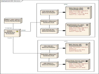
UML deployment diagrams show the physical deployment of software components across hardware infrastructure. They depict the hardware elements like processors and devices, the software installed on each processor, and how the components connect. Deployment diagrams are created during system implementation to layout the physical architecture and are useful for embedded, client-server, and distributed systems to distinguish interfaces from data and host multiple software versions across servers.
In this document
Powered by AI
Overview of the topic of UML deployment diagrams presented by Asraa Batool.
Definition and explanation of deployment diagrams as architectural models representing environmental structure.
Illustrates how UML deployment diagrams depict the physical deployment of software components on processors.
Details on how UML deployment diagrams are created during system implementation showing physical arrangements.
Explains the role of nodes in deployment diagrams, indicating hardware devices that support system runtime.
Describes the useful scenarios for deployment diagrams, including embedded systems and client/server setups.
What are Deployment
diagrams?
O Deployment diagrams are a kind of
architectural model that show the static
structure of the planned target
environment.
3.
UML deployment
diagrams
O UML deployment diagrams show how
software components are physically deployed
on processors; that is, the deployment
diagram shows the hardware and software in
the system used to connect the different
components in the system.
4.
Creation
O UML deploymentdiagrams usually created
during the implementation of the system
and set out the physical arrangement of
the processor elements, the software that
are installed on each processor, and the
components and other elements that the
software implements.
6.
Cont…
O nodes ina deployment diagram can show
hardware devices such as sensors, and
printers, as well as other devices that
support the runtime environment of a
system.
7.
uses
O Deployment diagramsare probably most useful when
you are designing an embedded system based on
hardware that is controlled by external stimuli.
Examples:
O A display that is controlled by temperature change.
O Use them to document client/server systems that typically
distinguish between the user interface and the persistent
data of a system.
O Distributed systems that have multiple servers and can
host multiple versions of software components.
In practice, deployment
diagrams are not universally
used.