UML Deployment
Diagrams: A
ComprehensiveOverview
Explore how deployment diagrams illustrate software's physical
architecture. Understand components, hardware, and communication
paths visually.
2.
Meet the Team
ADARSHMITTAL
RA2411032010064
HARSHIT AGARWAL
RA2411032010062
SAMSON JOHN ANTAO
RA2411032010061
NANDANA MANOJ
RA2411032010065
MOKESH P
RA2411032010067
IRSATH NOOR B
RA2411032010066
ATUL BHARADWAJ
RA2411032010060
3.
What is aUML Deployment Diagram?
Visualizes Software
Deployment
Maps physical deployment of
software artifacts and systems.
Shows Hardware-
Software Relationships
Displays how hardware nodes
host software components.
Illustrates System
Architecture
Depicts real-world production
environment setups.
Essential Planning Tool
Supports efficient deployment management.
Part of UML Toolkit
Works alongside component and other UML
diagrams.
4.
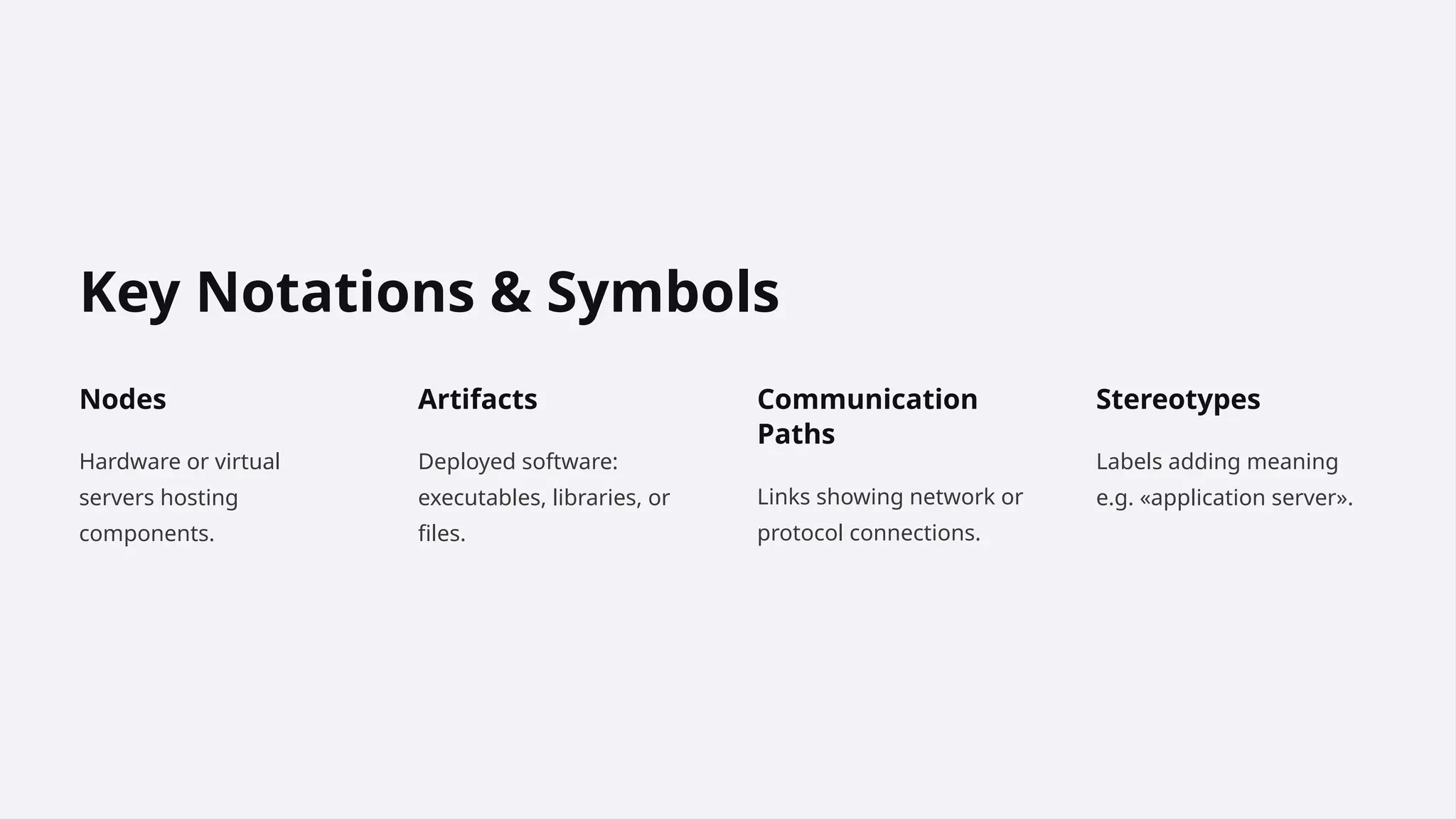
Key Notations &Symbols
Nodes
Hardware or virtual
servers hosting
components.
Artifacts
Deployed software:
executables, libraries, or
files.
Communication
Paths
Links showing network or
protocol connections.
Stereotypes
Labels adding meaning
e.g. «application server».
5.
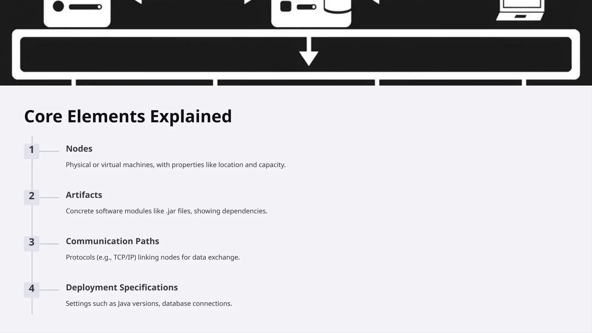
Core Elements Explained
1Nodes
Physical or virtual machines, with properties like location and capacity.
2 Artifacts
Concrete software modules like .jar files, showing dependencies.
3 Communication Paths
Protocols (e.g., TCP/IP) linking nodes for data exchange.
4 Deployment Specifications
Settings such as Java versions, database connections.
6.
Real-World Examples
E-commerce Platform
Multipleservers for performance and scalability.
Cloud-Based App
Uses load balancing and virtual machines.
Mobile App Deployment
Backend servers support app interactions.
7.
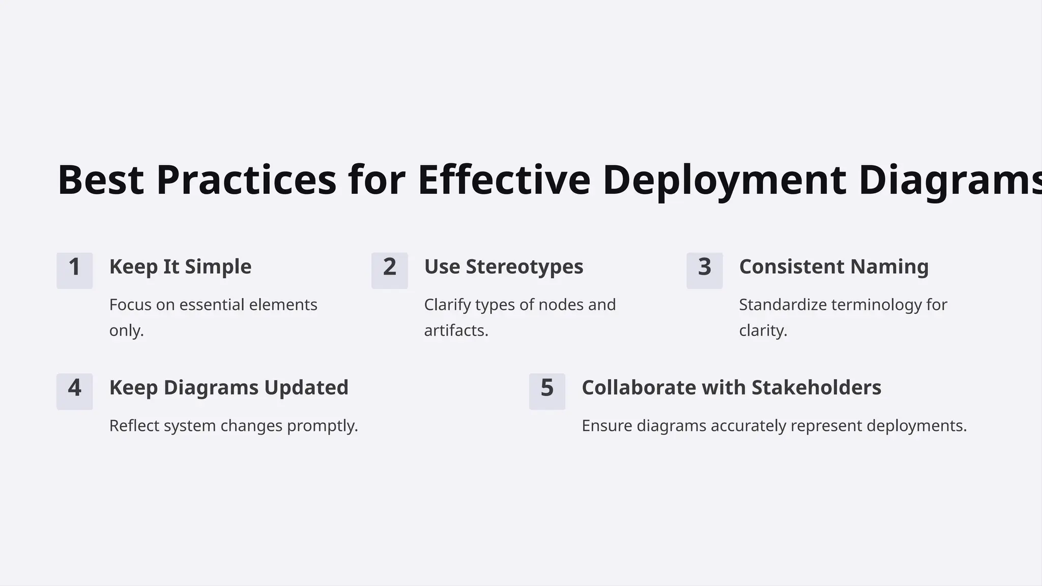
Best Practices forEffective Deployment Diagrams
1 Keep It Simple
Focus on essential elements
only.
2 Use Stereotypes
Clarify types of nodes and
artifacts.
3 Consistent Naming
Standardize terminology for
clarity.
4 Keep Diagrams Updated
Reflect system changes promptly.
5 Collaborate with Stakeholders
Ensure diagrams accurately represent deployments.
8.
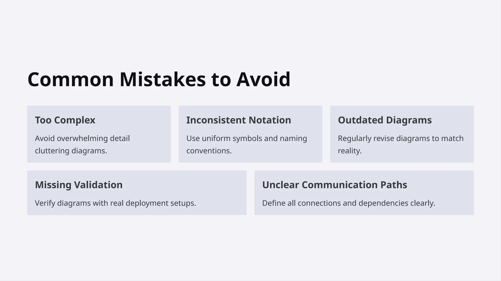
Common Mistakes toAvoid
Too Complex
Avoid overwhelming detail
cluttering diagrams.
Inconsistent Notation
Use uniform symbols and naming
conventions.
Outdated Diagrams
Regularly revise diagrams to match
reality.
Missing Validation
Verify diagrams with real deployment setups.
Unclear Communication Paths
Define all connections and dependencies clearly.
9.
Conclusion: Mastering UMLDeployment
Diagrams
Deployment diagrams clarify implementation architectures.
They reduce errors and enhance team communication.
Following best practices keeps diagrams practical.
Consistent updates ensure ongoing accuracy and
relevance.