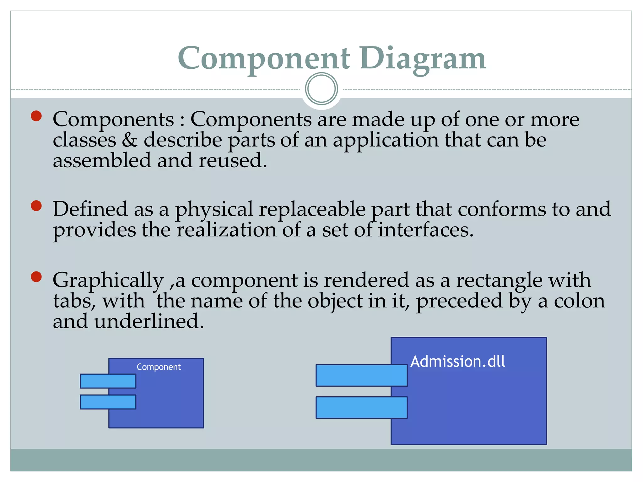
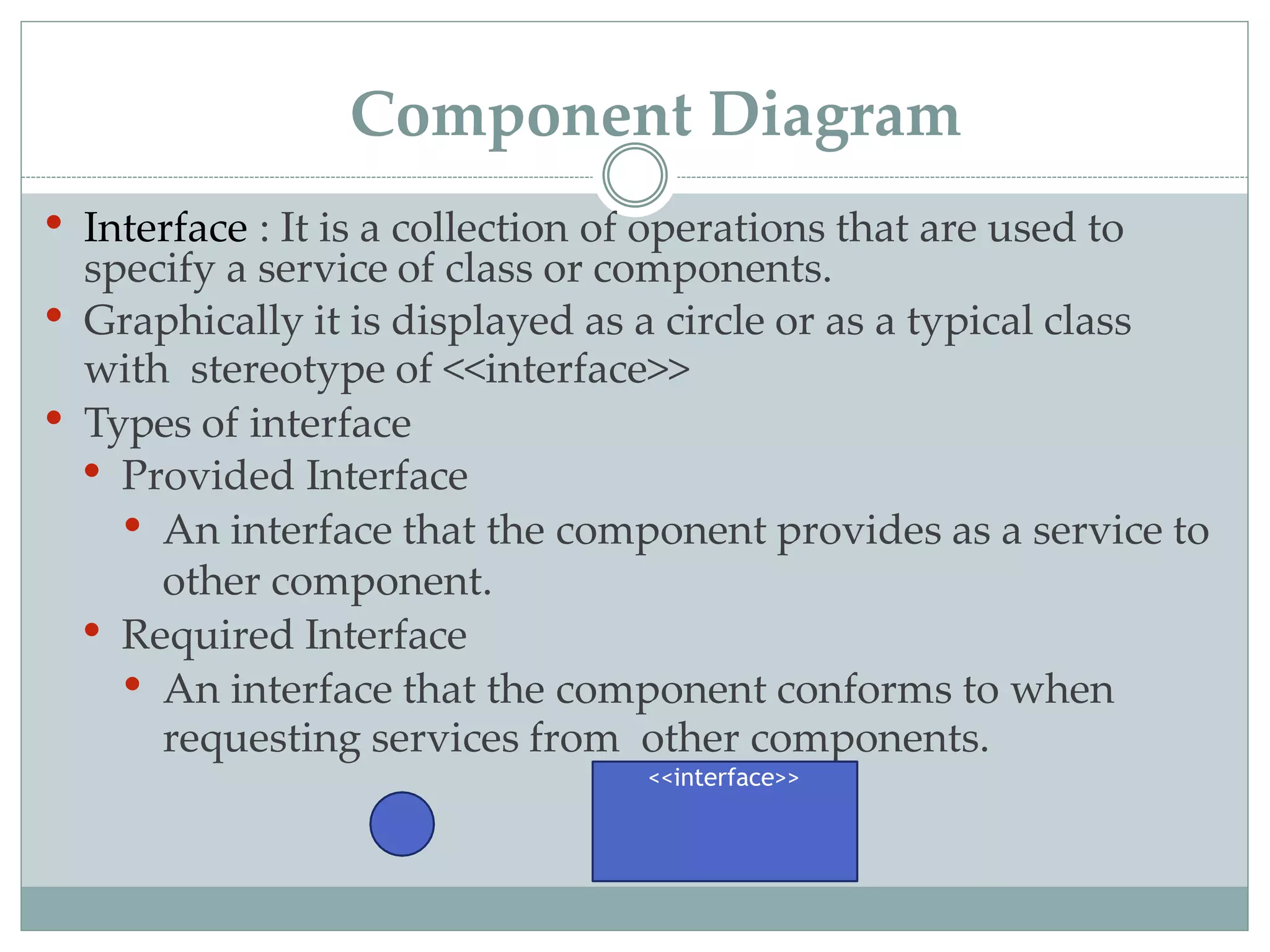
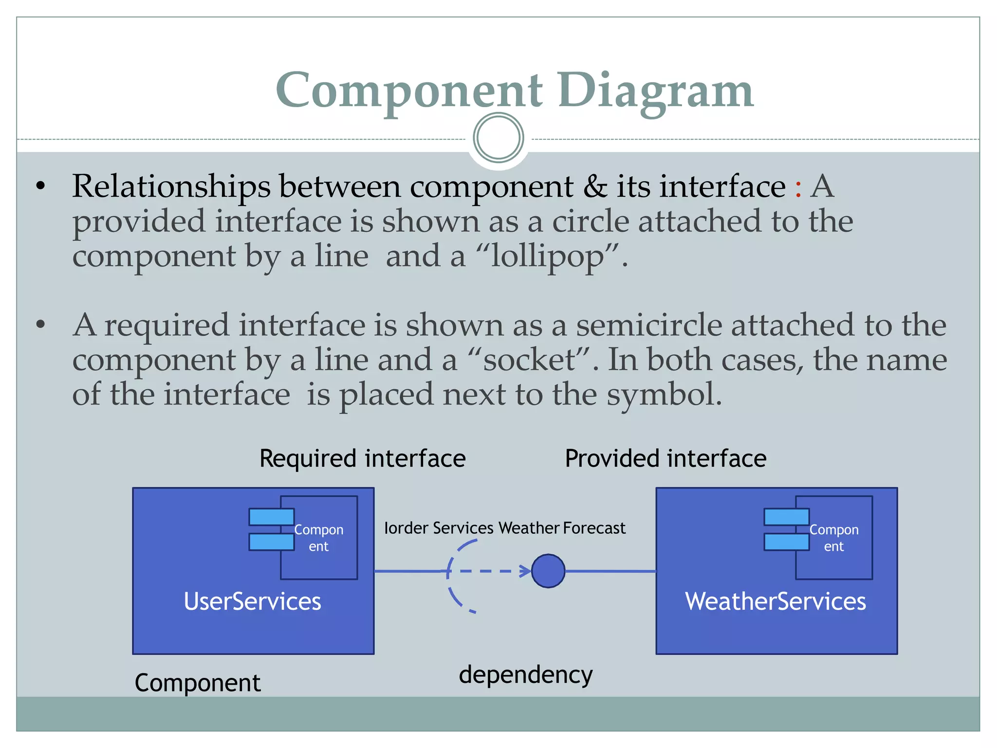
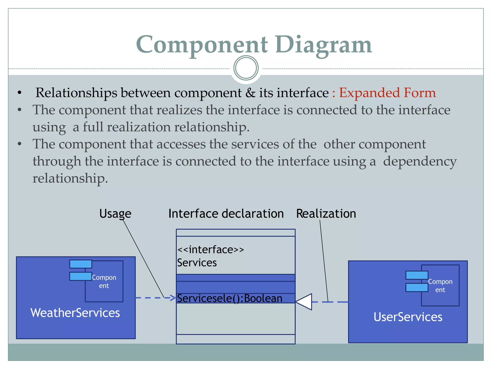
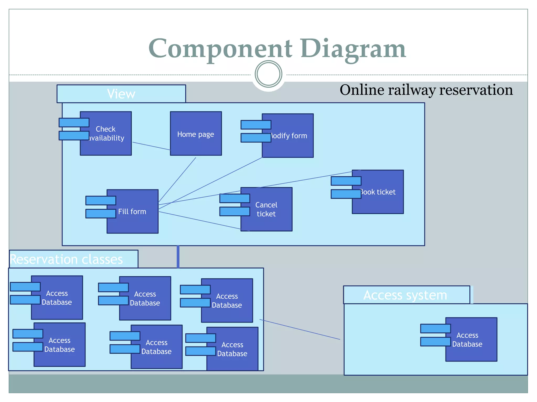
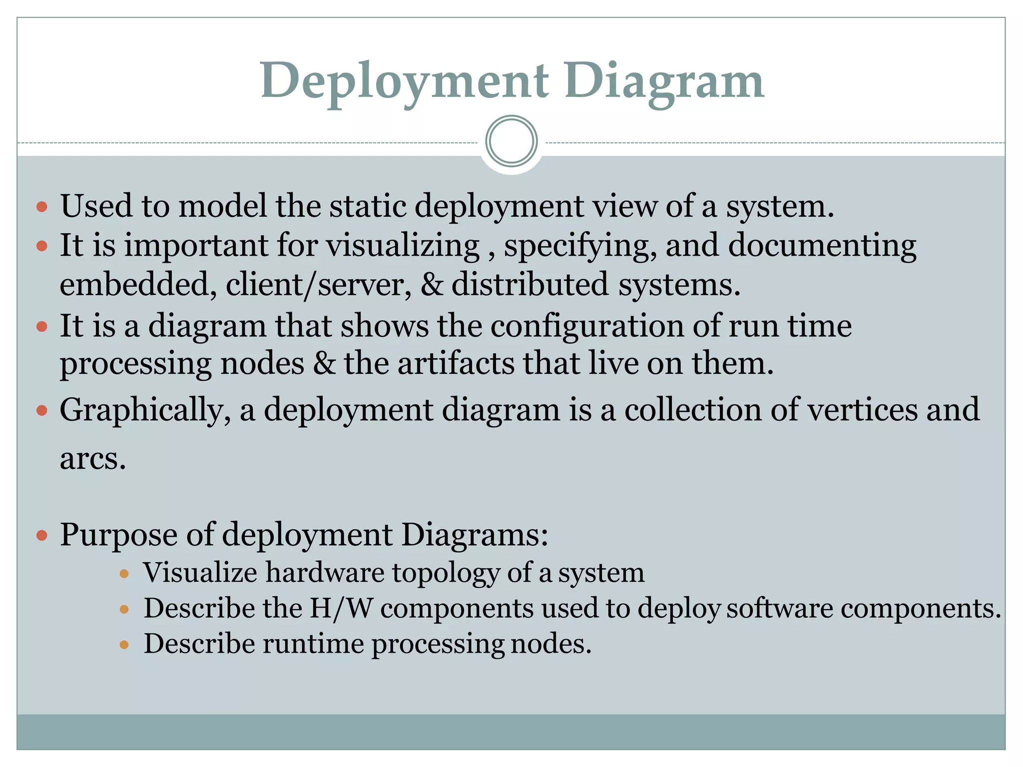
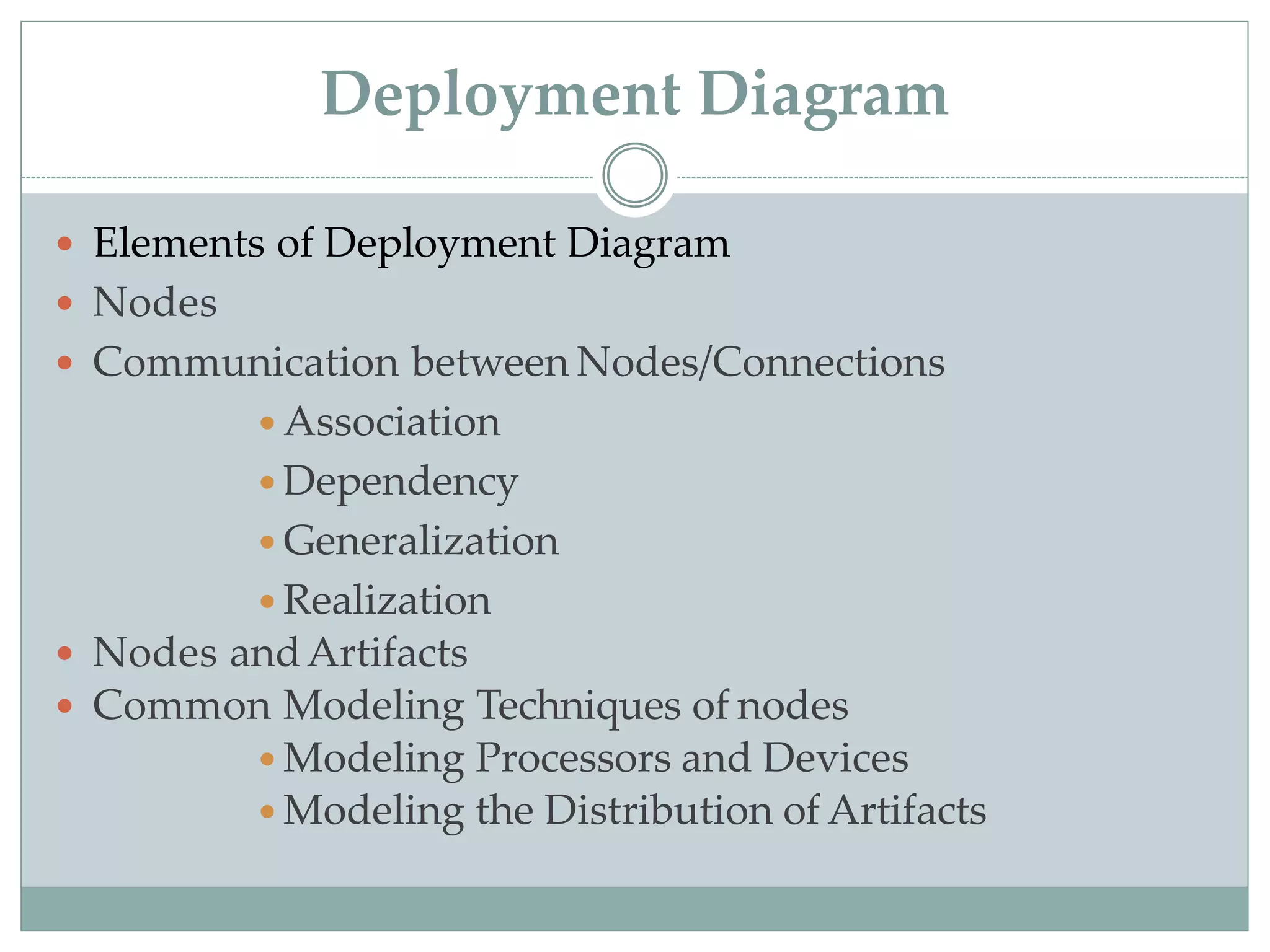
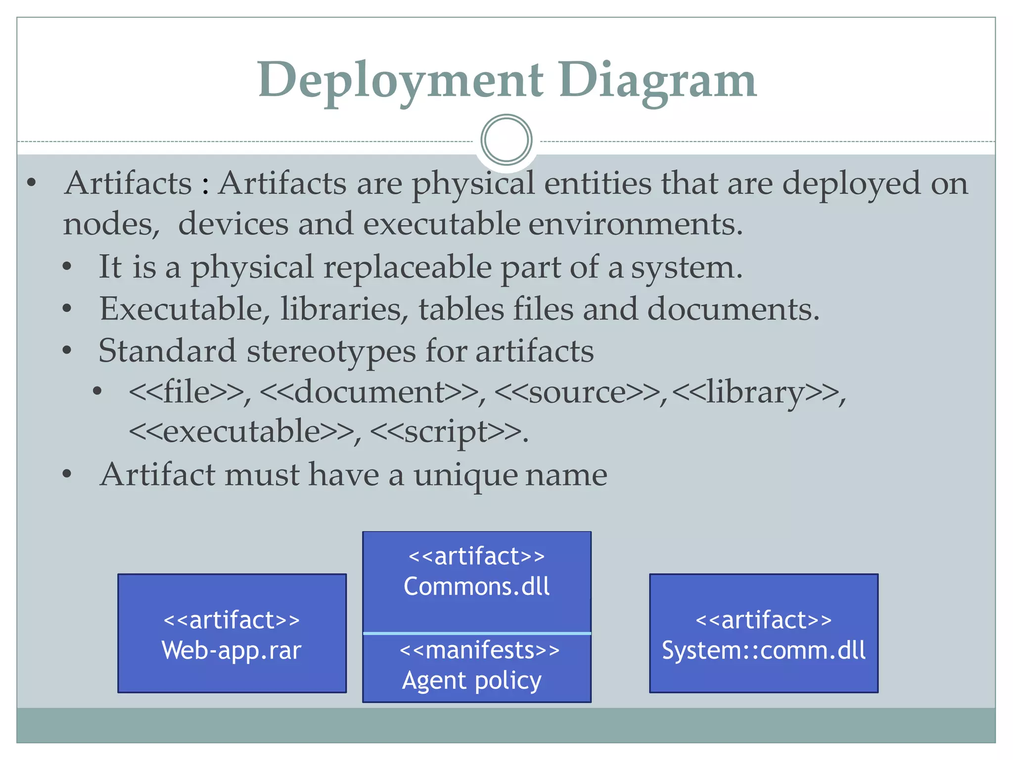
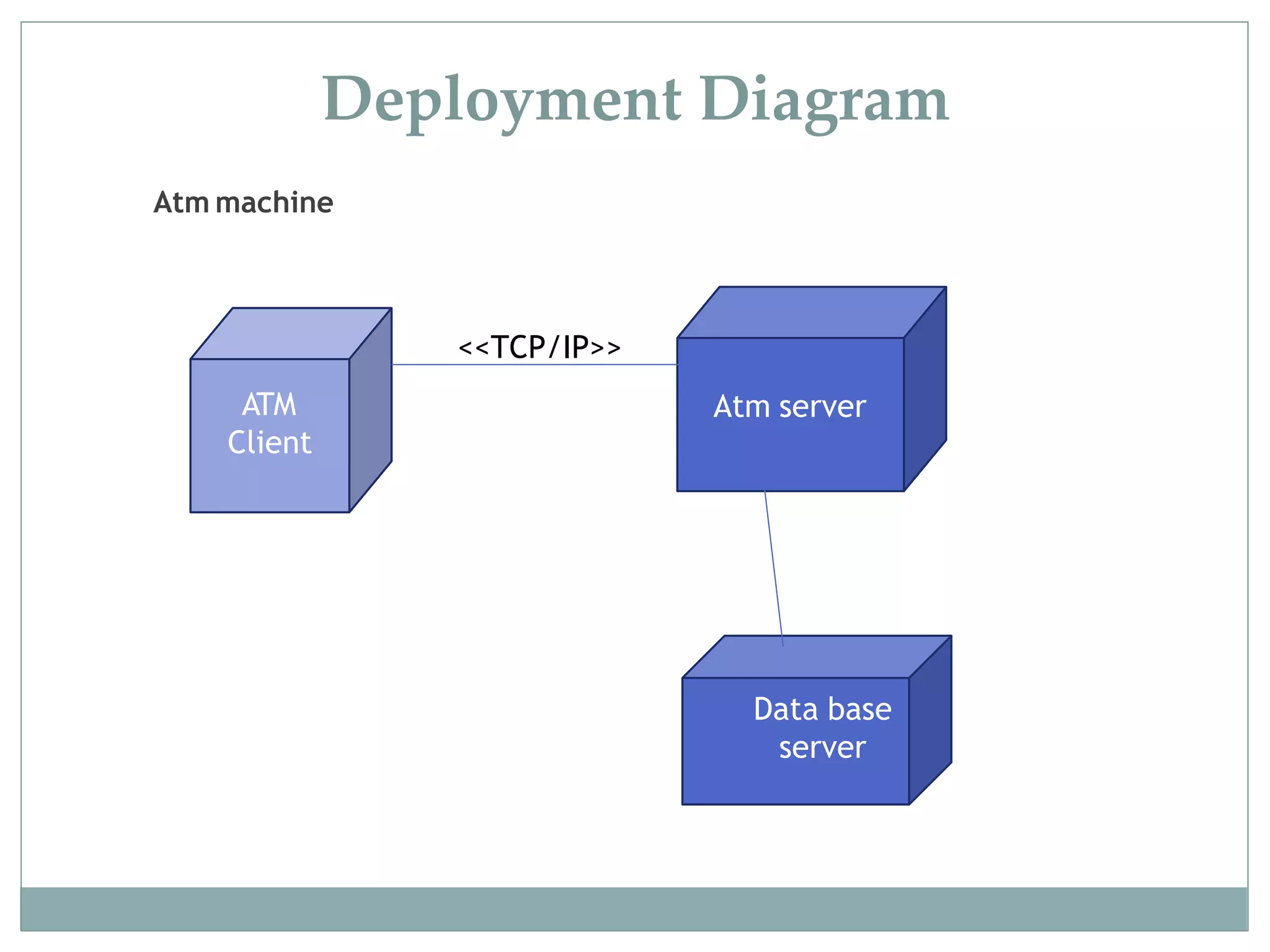
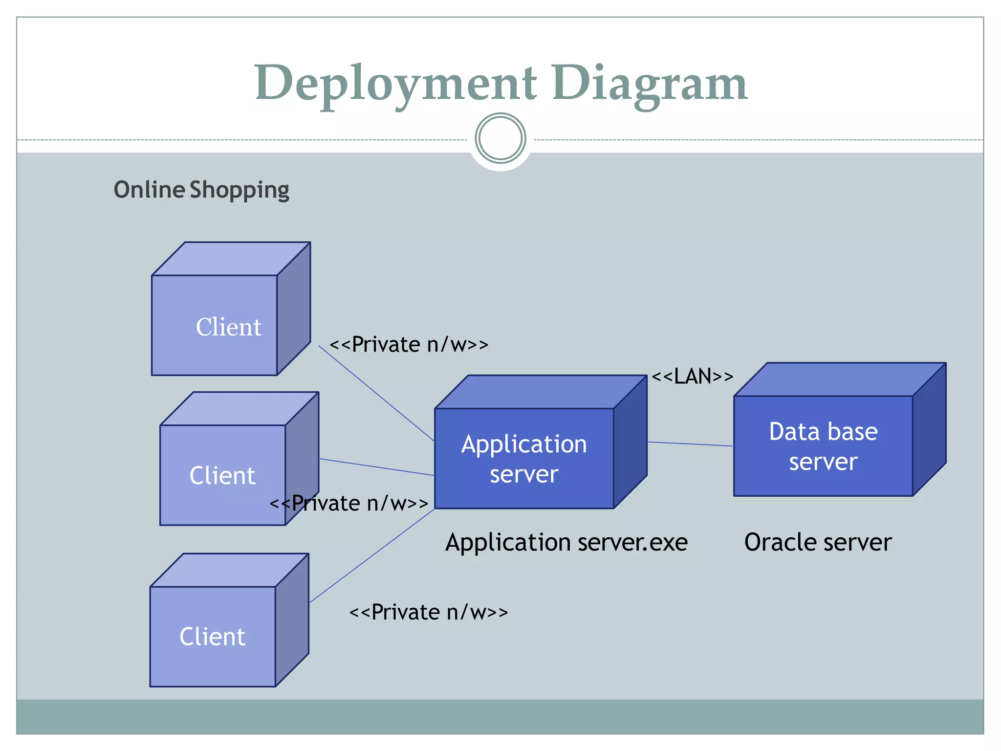
T.Y. B.Sc. (Comp. Sci.) Sem I
Object Oriented Software Engineering
(OOSE)
CS-336
Faculty
Dr. Amit D. Kasliwal
Asst. Professor
Chapter 7
Architectural Modeling
Overview
 Component
 Components Diagram
 Deployment Diagram
 Collaboration Diagram
Architectural Modeling
 An architecture is the set of significant decisions about the
organization of a software system.
 Guides about the elements, their interfaces their
collaborations and their composition.
 Architecture can be defined at both a logical and
physical level.
 Logical Architecture: It shows more generic view of the
architecture.
 Physical Architecture: Describes in more details how the
software and systems are designed.
Component Diagram
 Component diagrams are one of the two kinds of diagrams found
in modeling the physical aspects of object-oriented systems.
 It shows organizations & dependencies among set of components.
 It describe the organization of physical s/w components,
including source code, run time code & executable.
 Addresses static implementation view of a system .it represents
the high-level parts that make up the system.
 High level reusable parts of a system are represented in it.
 Visualize the static aspect of the physical components and their
relationships and to specify their details for construction.
 Collecting various executable, libraries, files, tables (physical
things)
 Elements Of a Component Diagram
 Components
 Interfaces
 Ports
 Connectors
Component Diagram
 Components : Components are made up of one or more
classes & describe parts of an application that can be
assembled and reused.
 Defined as a physical replaceable part that conforms to and
provides the realization of a set of interfaces.
 Graphically ,a component is rendered as a rectangle with
tabs, with the name of the object in it, preceded by a colon
and underlined.
Component Admission.dll
Component Diagram
• Interface : It is a collection of operations that are used to
specify a service of class or components.
• Graphically it is displayed as a circle or as a typical class
with stereotype of <<interface>>
• Types of interface
• Provided Interface
• An interface that the component provides as a service to
other component.
• Required Interface
• An interface that the component conforms to when
requesting services from other components.
<<interface>>
Component Diagram
• Relationships between component & its interface : A
provided interface is shown as a circle attached to the
component by a line and a “lollipop”.
• A required interface is shown as a semicircle attached to the
component by a line and a “socket”. In both cases, the name
of the interface is placed next to the symbol.
UserServices
Compon
ent
WeatherServices
Compon
ent
Component
Iorder Services Weather Forecast
dependency
Required interface Provided interface
Component Diagram
• Relationships between component & its interface : Expanded Form
• The component that realizes the interface is connected to the interface
using a full realization relationship.
• The component that accesses the services of the other component
through the interface is connected to the interface using a dependency
relationship.
UserServices
Compon
ent
WeatherServices
Compon
ent
<<interface>>
Services
Servicesele():Boolean
Usage Interface declaration Realization
Component Diagram
• Ports :Ports are used to control the implementation of all the
operations in all of the provided interfaces in the component.
• It is an explicit window into an encapsulatedcomponent.
• All of the interactions into and out of the component pass
through ports. It has identity.
• Component can communicate with the component througha
specific port.
• It is shown as a small square straddling the border of a
component. Both provided and required interfaces may be
attached to the port symbol.
• A provided interface represents a service that can be requested
through that port. A required interface represents a service that
the port needs to obtain from some other component.
Component Diagram
Compon
ent
Port
Ticket
Seller
Attractio
ns
Booking
Credit
cards
Required
Charging
Component
declaration Port
name
Interface
name
Ticket salesNormal
sales
Priority
sales
Ticket sales
Load
Attractio
ns
Provided
interfaceJAYA
interface
Component Diagram
• Connectors : A wire between two port is calledconnector.
• It represent a link or a transient link. Instance of an ordinary
• association.
• A transient link represents a usage relationship between
two components.
• If two components are explicitly wired together, either directly
or through ports, just draw a line between them or their ports.
• If two components are connected because they have compatible
interface, you can use a ball-and-socket notation to show that
there is no inherent relationship between the components,
although they are connected inside this component.
• Types of Connector
• Direct connector Delegation connector
Component Diagram
Connectors
Catalog sales
:order taking :OrderHandling
:inventry
:Fullfillment
FindItems
Direct connector
Shipments
Changing :Credit:OrderHandoff
Delegation Connector
:orderEntry
Connector by interface
12
Component Diagram
Online railway
reservation login form
Online railway reservation
Access
Database
Cancel
ticketFill form
Modify formHome page
Check
availability
Access
Database
Access
Database
Access
Database
Access
Database
Access
Database
Access
Database
Book ticket
View
Reservation classes
Access system
Component Diagram
Deployment Diagram
 Used to model the static deployment view of a system.
 It is important for visualizing , specifying, and documenting
embedded, client/server, & distributed systems.
 It is a diagram that shows the configuration of run time
processing nodes & the artifacts that live on them.
 Graphically, a deployment diagram is a collection of vertices and
arcs.
 Purpose of deployment Diagrams:
 Visualize hardware topology of a system
 Describe the H/W components used to deploy software components.
 Describe runtime processing nodes.
Deployment Diagram
 Elements of Deployment Diagram
 Nodes
 Communication between Nodes/Connections
 Association
 Dependency
 Generalization
 Realization
 Nodes andArtifacts
 Common Modeling Techniques of nodes
 Modeling Processors and Devices
 Modeling the Distribution of Artifacts
• Artifacts
• Kinds of Artifacts
• Deployment artifacts
• Work product artifacts
• Execution Artifacts
• Common Modeling Techniques of Artifacts
• Modeling Execution and Libraries
• Modeling Tables, Files , and Documents
• Modeling Source Code
Deployment Diagram
• Node: Just like artifacts, are an important building block in
modeling the physical aspects of a system
• It is a physical elements that exists at run time & represents a
computational resource.
• Graphical representation of node is cube.
• Types of node
• Processor
• It is a piece of hardware capable of executing programs
• A Processor can have list of processes on it.
• Represented as shaded cube with name of the object.
• Device
• A device is apiece of hardware incapable of executing program.
• Device will also have on a cube.
modem
Deployment Diagram
• Communication between Nodes/ Connections:
• Association: It refers to a physical connection or link
between the nodes.
• It is shown as a solid-line between nodes.
Business-
Processing
server
Desktop
Client
Deployment Diagram
• Communication between Nodes/ Connections:
• Dependency : It is a relationship that indicates that a
model element is in some way dependent of another
model element.
• Dependency of a node on components is depicted
using dashed lines.
Application
Server
Sqlserv.e
xe<<dependency>>
Deployment Diagram
• Communication between Nodes/ Connections:
• Generalization: It is a relationship between a parent
node and child node
• It is shown as a solid-line with triangle between nodes.
parent
child
Deployment Diagram
• Communication between Nodes/ Connections:
• Realization : It is a relationship between interface and
classes or components that realize them
• It shows as a dashed line with hollow triangle.
• Example the relationship between a interface and a class
that realizes or execute that interface
Parser
HTML
Parser
Deployment Diagram
Modeling Processors and devices
<<Processor>>
server RAID farm
<<RS-232>>
<<10-T Ethernet>>
Kiosk
console
Deployment Diagram
Modeling the Distribution ofArtifacts
S:server
processorSpeed=
300 mHz
Mem=128 meg
Deploys
Dbadmin.exe
RAID farm
<<RS-232>>
<<10-T Ethernet>>
Kiosk
C:console
Deploys
Admin.exe
Config.exe
console
:kiosk
Deploys
User.exe
:RAID FARM
Deployment Diagram
• Artifacts : Artifacts are physical entities that are deployed on
nodes, devices and executable environments.
• It is a physical replaceable part of a system.
• Executable, libraries, tables files and documents.
• Standard stereotypes for artifacts
• <<file>>, <<document>>, <<source>>,<<library>>,
<<executable>>, <<script>>.
• Artifact must have a unique name
<<artifact>>
Web-app.rar
<<artifact>>
System::comm.dll
<<artifact>>
Commons.dll
<<manifests>>
Agent policy
Deployment Diagram
Atm machine
Atm server
Data base
server
ATM
Client
<<TCP/IP>>
Deployment Diagram
Online Shopping
Application
server
Data base
server
Client
<<LAN>>
Client
Application server.exe Oracle server
<<Private n/w>>
Client
<<Private n/w>>
<<Private n/w>>
Deployment Diagram
Railway reservation
Applicati
on server
Data base
server
Client
<<LAN>>
Client
Client
Application server.exe Oracle server
<<Private n/w>>
Railway
reservation
server
Printer
Deployment Diagram
Collaboration Diagram
 A collaboration diagram is an interaction diagram that
emphasizes the structural organization of the objects that
send and receive messages.
 It is used to represent more-complex flows, involving
iterations & branching.
 Sequence diagrams and collaboration diagrams are
semantically equivalent that means conversion to the other
is possible without any loss of information.
 Graphically it is a collection of vertices and arcs.
 Following are the components of a Collaboration diagram:
 Objects: The representation of an object is done by an object
symbol with its name and class underlined, separated by a colon.
 Actors: Each actor has its respective role and name. In this, one
actor initiates the use case.
 Links: The link is an instance of association, which associates the
objects and actors.
 Link portrays a relationship between the objects through which
the messages are sent. It is represented by a solid line.
 The link helps an object to connect with or navigate to another
object, such that the message flows are attached to links.
 Messages: It is a communication between objects which carries
information.
 Collaboration diagrams have two features that distinguish
them from sequence diagrams.
 First, there is the path to indicate how one object is linked
to another, attach a path stereotype to the far end of a link
such as local, parameter, global, and self.
 Second, there is the sequence number to indicate the time
order of a message denoted by prefixing the message with
a number, nesting is indicated by Dewey decimal
numbering (e.g.:- 1 is the first message; 1.1 is the nested in
message 1.) used for the given example .
Architectural Modeling

Architectural Modeling

  • 1.
    T.Y. B.Sc. (Comp.Sci.) Sem I Object Oriented Software Engineering (OOSE) CS-336 Faculty Dr. Amit D. Kasliwal Asst. Professor
  • 2.
    Chapter 7 Architectural Modeling Overview Component  Components Diagram  Deployment Diagram  Collaboration Diagram
  • 3.
    Architectural Modeling  Anarchitecture is the set of significant decisions about the organization of a software system.  Guides about the elements, their interfaces their collaborations and their composition.  Architecture can be defined at both a logical and physical level.  Logical Architecture: It shows more generic view of the architecture.  Physical Architecture: Describes in more details how the software and systems are designed.
  • 4.
    Component Diagram  Componentdiagrams are one of the two kinds of diagrams found in modeling the physical aspects of object-oriented systems.  It shows organizations & dependencies among set of components.  It describe the organization of physical s/w components, including source code, run time code & executable.  Addresses static implementation view of a system .it represents the high-level parts that make up the system.  High level reusable parts of a system are represented in it.  Visualize the static aspect of the physical components and their relationships and to specify their details for construction.  Collecting various executable, libraries, files, tables (physical things)
  • 5.
     Elements Ofa Component Diagram  Components  Interfaces  Ports  Connectors Component Diagram
  • 6.
     Components :Components are made up of one or more classes & describe parts of an application that can be assembled and reused.  Defined as a physical replaceable part that conforms to and provides the realization of a set of interfaces.  Graphically ,a component is rendered as a rectangle with tabs, with the name of the object in it, preceded by a colon and underlined. Component Admission.dll Component Diagram
  • 7.
    • Interface :It is a collection of operations that are used to specify a service of class or components. • Graphically it is displayed as a circle or as a typical class with stereotype of <<interface>> • Types of interface • Provided Interface • An interface that the component provides as a service to other component. • Required Interface • An interface that the component conforms to when requesting services from other components. <<interface>> Component Diagram
  • 8.
    • Relationships betweencomponent & its interface : A provided interface is shown as a circle attached to the component by a line and a “lollipop”. • A required interface is shown as a semicircle attached to the component by a line and a “socket”. In both cases, the name of the interface is placed next to the symbol. UserServices Compon ent WeatherServices Compon ent Component Iorder Services Weather Forecast dependency Required interface Provided interface Component Diagram
  • 9.
    • Relationships betweencomponent & its interface : Expanded Form • The component that realizes the interface is connected to the interface using a full realization relationship. • The component that accesses the services of the other component through the interface is connected to the interface using a dependency relationship. UserServices Compon ent WeatherServices Compon ent <<interface>> Services Servicesele():Boolean Usage Interface declaration Realization Component Diagram
  • 10.
    • Ports :Portsare used to control the implementation of all the operations in all of the provided interfaces in the component. • It is an explicit window into an encapsulatedcomponent. • All of the interactions into and out of the component pass through ports. It has identity. • Component can communicate with the component througha specific port. • It is shown as a small square straddling the border of a component. Both provided and required interfaces may be attached to the port symbol. • A provided interface represents a service that can be requested through that port. A required interface represents a service that the port needs to obtain from some other component. Component Diagram
  • 11.
  • 12.
    • Connectors :A wire between two port is calledconnector. • It represent a link or a transient link. Instance of an ordinary • association. • A transient link represents a usage relationship between two components. • If two components are explicitly wired together, either directly or through ports, just draw a line between them or their ports. • If two components are connected because they have compatible interface, you can use a ball-and-socket notation to show that there is no inherent relationship between the components, although they are connected inside this component. • Types of Connector • Direct connector Delegation connector Component Diagram
  • 13.
    Connectors Catalog sales :order taking:OrderHandling :inventry :Fullfillment FindItems Direct connector Shipments Changing :Credit:OrderHandoff Delegation Connector :orderEntry Connector by interface 12 Component Diagram
  • 14.
  • 15.
    Online railway reservation Access Database Cancel ticketFillform Modify formHome page Check availability Access Database Access Database Access Database Access Database Access Database Access Database Book ticket View Reservation classes Access system Component Diagram
  • 16.
    Deployment Diagram  Usedto model the static deployment view of a system.  It is important for visualizing , specifying, and documenting embedded, client/server, & distributed systems.  It is a diagram that shows the configuration of run time processing nodes & the artifacts that live on them.  Graphically, a deployment diagram is a collection of vertices and arcs.  Purpose of deployment Diagrams:  Visualize hardware topology of a system  Describe the H/W components used to deploy software components.  Describe runtime processing nodes.
  • 17.
    Deployment Diagram  Elementsof Deployment Diagram  Nodes  Communication between Nodes/Connections  Association  Dependency  Generalization  Realization  Nodes andArtifacts  Common Modeling Techniques of nodes  Modeling Processors and Devices  Modeling the Distribution of Artifacts
  • 18.
    • Artifacts • Kindsof Artifacts • Deployment artifacts • Work product artifacts • Execution Artifacts • Common Modeling Techniques of Artifacts • Modeling Execution and Libraries • Modeling Tables, Files , and Documents • Modeling Source Code Deployment Diagram
  • 19.
    • Node: Justlike artifacts, are an important building block in modeling the physical aspects of a system • It is a physical elements that exists at run time & represents a computational resource. • Graphical representation of node is cube. • Types of node • Processor • It is a piece of hardware capable of executing programs • A Processor can have list of processes on it. • Represented as shaded cube with name of the object. • Device • A device is apiece of hardware incapable of executing program. • Device will also have on a cube. modem Deployment Diagram
  • 20.
    • Communication betweenNodes/ Connections: • Association: It refers to a physical connection or link between the nodes. • It is shown as a solid-line between nodes. Business- Processing server Desktop Client Deployment Diagram
  • 21.
    • Communication betweenNodes/ Connections: • Dependency : It is a relationship that indicates that a model element is in some way dependent of another model element. • Dependency of a node on components is depicted using dashed lines. Application Server Sqlserv.e xe<<dependency>> Deployment Diagram
  • 22.
    • Communication betweenNodes/ Connections: • Generalization: It is a relationship between a parent node and child node • It is shown as a solid-line with triangle between nodes. parent child Deployment Diagram
  • 23.
    • Communication betweenNodes/ Connections: • Realization : It is a relationship between interface and classes or components that realize them • It shows as a dashed line with hollow triangle. • Example the relationship between a interface and a class that realizes or execute that interface Parser HTML Parser Deployment Diagram
  • 24.
    Modeling Processors anddevices <<Processor>> server RAID farm <<RS-232>> <<10-T Ethernet>> Kiosk console Deployment Diagram
  • 25.
    Modeling the DistributionofArtifacts S:server processorSpeed= 300 mHz Mem=128 meg Deploys Dbadmin.exe RAID farm <<RS-232>> <<10-T Ethernet>> Kiosk C:console Deploys Admin.exe Config.exe console :kiosk Deploys User.exe :RAID FARM Deployment Diagram
  • 26.
    • Artifacts :Artifacts are physical entities that are deployed on nodes, devices and executable environments. • It is a physical replaceable part of a system. • Executable, libraries, tables files and documents. • Standard stereotypes for artifacts • <<file>>, <<document>>, <<source>>,<<library>>, <<executable>>, <<script>>. • Artifact must have a unique name <<artifact>> Web-app.rar <<artifact>> System::comm.dll <<artifact>> Commons.dll <<manifests>> Agent policy Deployment Diagram
  • 27.
    Atm machine Atm server Database server ATM Client <<TCP/IP>> Deployment Diagram
  • 28.
    Online Shopping Application server Data base server Client <<LAN>> Client Applicationserver.exe Oracle server <<Private n/w>> Client <<Private n/w>> <<Private n/w>> Deployment Diagram
  • 29.
    Railway reservation Applicati on server Database server Client <<LAN>> Client Client Application server.exe Oracle server <<Private n/w>> Railway reservation server Printer Deployment Diagram
  • 30.
    Collaboration Diagram  Acollaboration diagram is an interaction diagram that emphasizes the structural organization of the objects that send and receive messages.  It is used to represent more-complex flows, involving iterations & branching.  Sequence diagrams and collaboration diagrams are semantically equivalent that means conversion to the other is possible without any loss of information.  Graphically it is a collection of vertices and arcs.
  • 31.
     Following arethe components of a Collaboration diagram:  Objects: The representation of an object is done by an object symbol with its name and class underlined, separated by a colon.  Actors: Each actor has its respective role and name. In this, one actor initiates the use case.  Links: The link is an instance of association, which associates the objects and actors.  Link portrays a relationship between the objects through which the messages are sent. It is represented by a solid line.  The link helps an object to connect with or navigate to another object, such that the message flows are attached to links.  Messages: It is a communication between objects which carries information.
  • 32.
     Collaboration diagramshave two features that distinguish them from sequence diagrams.  First, there is the path to indicate how one object is linked to another, attach a path stereotype to the far end of a link such as local, parameter, global, and self.  Second, there is the sequence number to indicate the time order of a message denoted by prefixing the message with a number, nesting is indicated by Dewey decimal numbering (e.g.:- 1 is the first message; 1.1 is the nested in message 1.) used for the given example .