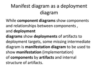
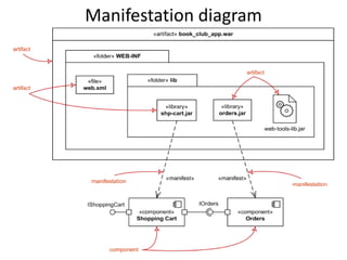
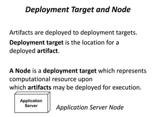
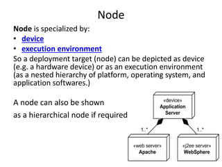
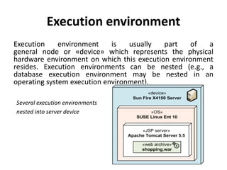
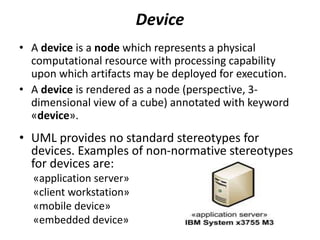
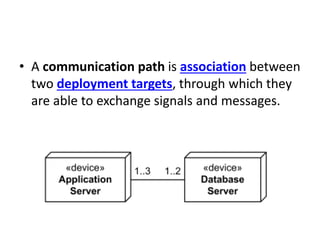
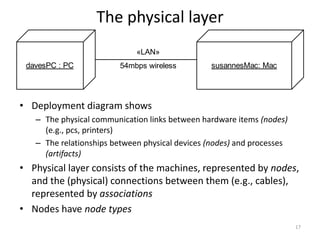
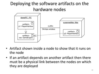
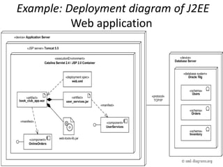
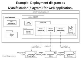
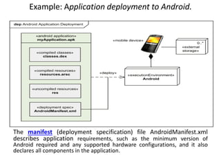
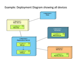
2. Deployment Diagram
Deployment diagram is a static UML diagram
which shows execution architecture of software
systems that represent the assignment
(deployment) of software artifacts to
deployment targets (usually nodes).
3. Nodes and Artifacts
• Nodes represent either hardware devices or
software execution environments. They could
be connected through communication paths
to create network systems of arbitrary
complexity.
• Artifacts represent concrete elements in the
physical world that are the result of a
development process and are deployed on
nodes.
4. How to use?
In UML 2.x artifacts are deployed to nodes, and
artifacts could manifest (implement)
components. So components are now deployed
to nodes indirectly through artifacts.
5. Components of Deployment diagram
The following nodes and edges are typically drawn in a UML deployment
diagram:
• Deployment,
• Artifact,
• Association Between Artifacts,
• Dependency Between Artifacts,
• Component,
• Manifestation,
• Node,
• Device,
• Execution Environment,
• Composition Of Nodes,
• Communication Path,
• Deployment Specification,
• Deployment Specification Dependency,
• Deployment Specification Association.
6. 6
Artifacts
«artifact»
Order.jar
«artifact»
Order.jar
«component»
Order
«manifest»
• In real life, an artifact is a concrete element in the physical
world
• In the context of software development, an artifact is the
specification of a physical piece of information such as a binary
executable, a database table or an implemented component
such as a DLL or a Java class file
• Each artifact has a filename
• An artifact is represented by a normal class rectangle with the
keyword <<artifact>> or an artifact icon in the top right corner
• Name of artifact may (optionally) be underlined
• Artifact is said to manifest model elements that are used to
construct the artifact
– Manifestation indicated by dependency arrow with keyword
<<manifest>>
7. Manifestation
Manifestation is an abstraction relationship
which represents concrete physical rendering
(implementation) of one or more model
elements by an artifact
In UML 2.0 and above, artifacts can manifest
any package able elements (e.g., components)
8. • A manifestation is notated in the same way
as abstraction, i.e. as a dashed line with an
open arrow head directed
from artifact to packageable element, (e.g.
to component or package) and is labeled with
the keyword «manifest».
9. EJB component UserService and skeleton of web services
are manifested (implemented) by EJB module user-service.jar
artifact
10. Manifest diagram as a deployment
diagram
While component diagrams show components
and relationships between components ,
and deployment
diagrams show deployments of artifacts to
deployment targets, some missing intermediate
diagram is manifestation diagram to be used to
show manifestation (implementation)
of components by artifacts and internal
structure of artifacts.
12. Deployment Target and Node
Artifacts are deployed to deployment targets.
Deployment target is the location for a
deployed artifact.
A Node is a deployment target which represents
computational resource upon
which artifacts may be deployed for execution.
Application Server Node
13. Node
Node is specialized by:
• device
• execution environment
So a deployment target (node) can be depicted as device
(e.g. a hardware device) or as an execution environment
(as a nested hierarchy of platform, operating system, and
application softwares.)
A node can also be shown
as a hierarchical node if required
14. Execution environment
Execution environment is usually part of a
general node or «device» which represents the physical
hardware environment on which this execution environment
resides. Execution environments can be nested (e.g., a
database execution environment may be nested in an
operating system execution environment).
Several execution environments
nested into server device
15. Device
• A device is a node which represents a physical
computational resource with processing capability
upon which artifacts may be deployed for execution.
• A device is rendered as a node (perspective, 3-
dimensional view of a cube) annotated with keyword
«device».
• UML provides no standard stereotypes for
devices. Examples of non-normative stereotypes
for devices are:
«application server»
«client workstation»
«mobile device»
«embedded device»
16. • A communication path is association between
two deployment targets, through which they
are able to exchange signals and messages.
17. 17
The physical layer
davesPC : PC susannesMac: Mac
«LAN»
54mbps wireless
• Deployment diagram shows
– The physical communication links between hardware items (nodes)
(e.g., pcs, printers)
– The relationships between physical devices (nodes) and processes
(artifacts)
• Physical layer consists of the machines, represented by nodes,
and the (physical) connections between them (e.g., cables),
represented by associations
• Nodes have node types
18. 18
Deploying the software artifacts on the
hardware nodes
davesPC : PC
susannesMac: Mac
«LAN»
54mbps wireless
«artifact»
oxo: GameEngine
«artifact»
p1: PlayerInterface
«artifact»
p2: PlayerInterface
• Artifact shown inside a node to show that it runs on
the node
• If an artifact depends on another artifact then there
must be a physical link between the nodes on which
they are deployed
21. Example: Application deployment to Android.
The manifest (deployment specification) file AndroidManifest.xml
describes application requirements, such as the minimum version of
Android required and any supported hardware configurations, and it also
declares all components in the application.