Downloaded 178 times


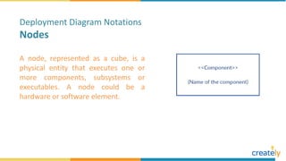


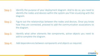


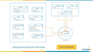
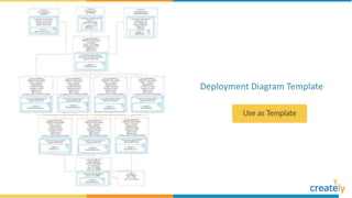
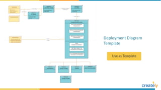


A deployment diagram shows the physical architecture of a system by modeling nodes, devices, and the communication between them. It depicts the hardware topology including nodes like hardware/software and middleware. A node is represented as a cube and can be a physical or software element. Artifacts, communication associations, and deployment specifications are also modeled. The document provides steps and examples for creating deployment diagrams.