Downloaded 653 times


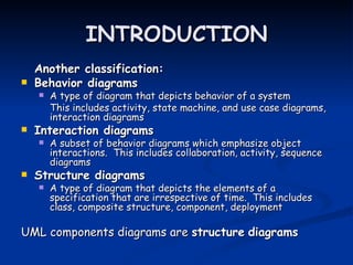
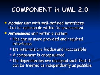


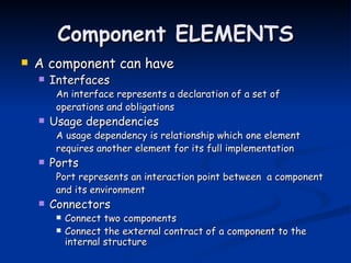
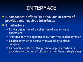
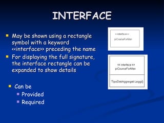
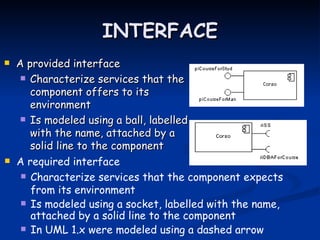
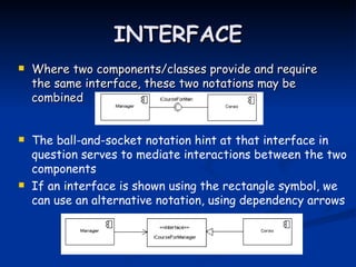
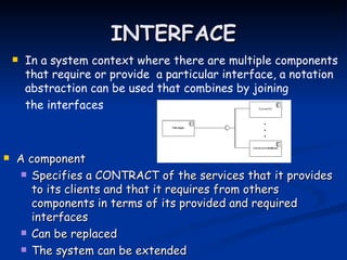

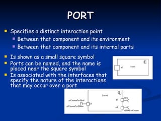


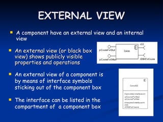
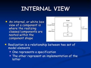
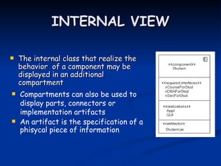
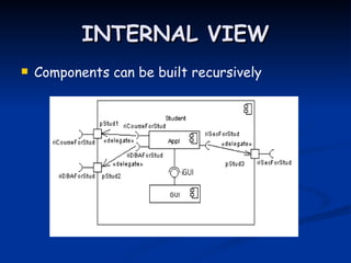
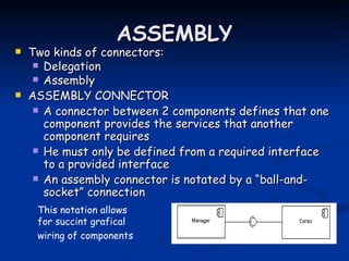


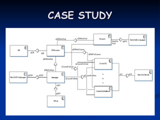


UML component diagrams describe the structure of software systems by showing components, their interfaces, and dependencies between components. A component represents a modular part of a system that encapsulates its contents and exposes its functionality through interfaces. Component diagrams show the organization and dependencies of components through their interfaces and ports using elements like components, interfaces, ports, and connectors. They allow modeling large and complex software systems in a modular way.