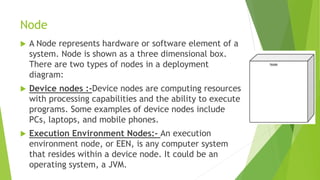
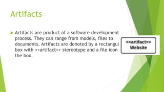
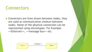
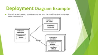
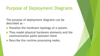
Deployment
Diagram
BY :- SAMARTH VAISH
Deployment Diagram
 Deployment Diagram Deployment Diagram is a
very simple diagram which is used to represent
the physical implementation of a system or a
physical architecture of a hardware. Deployment
diagram presents a static view of the system.
Elements of Deployment Diagram
There are only three elements for a deployment
diagram. They are :
 Node
 Artifact
 Connection
Node
 A Node represents hardware or software element of a
system. Node is shown as a three dimensional box.
There are two types of nodes in a deployment
diagram:
 Device nodes :-Device nodes are computing resources
with processing capabilities and the ability to execute
programs. Some examples of device nodes include
PCs, laptops, and mobile phones.
 Execution Environment Nodes:- An execution
environment node, or EEN, is any computer system
that resides within a device node. It could be an
operating system, a JVM.
Artifacts
 Artifacts are product of a software development
process. They can range from models, files to
documents. Artifacts are denoted by a rectangular
box with <<artifact>> stereotype and a file icon in
the box.
Connectors
 Connectors are lines drawn between nodes, they
are used as communication medium between
nodes. Name of the physical connection can be
represented using stereotypes. For Example
<<Ethernet>>, <<message bus>> etc.
Deployment Diagram Example
 There is a web server, a database server, and the machine where the user
views the website.
Purpose of Deployment Diagrams
The purpose of deployment diagrams can be
described as −
 Visualize the hardware topology of a system.
 They model physical hardware elements and the
communication paths between them
 Describe the runtime processing nodes.
Thank You!!

Deployment

  • 1.
  • 2.
    Deployment Diagram  DeploymentDiagram Deployment Diagram is a very simple diagram which is used to represent the physical implementation of a system or a physical architecture of a hardware. Deployment diagram presents a static view of the system.
  • 3.
    Elements of DeploymentDiagram There are only three elements for a deployment diagram. They are :  Node  Artifact  Connection
  • 4.
    Node  A Noderepresents hardware or software element of a system. Node is shown as a three dimensional box. There are two types of nodes in a deployment diagram:  Device nodes :-Device nodes are computing resources with processing capabilities and the ability to execute programs. Some examples of device nodes include PCs, laptops, and mobile phones.  Execution Environment Nodes:- An execution environment node, or EEN, is any computer system that resides within a device node. It could be an operating system, a JVM.
  • 5.
    Artifacts  Artifacts areproduct of a software development process. They can range from models, files to documents. Artifacts are denoted by a rectangular box with <<artifact>> stereotype and a file icon in the box.
  • 6.
    Connectors  Connectors arelines drawn between nodes, they are used as communication medium between nodes. Name of the physical connection can be represented using stereotypes. For Example <<Ethernet>>, <<message bus>> etc.
  • 7.
    Deployment Diagram Example There is a web server, a database server, and the machine where the user views the website.
  • 8.
    Purpose of DeploymentDiagrams The purpose of deployment diagrams can be described as −  Visualize the hardware topology of a system.  They model physical hardware elements and the communication paths between them  Describe the runtime processing nodes.
  • 9.