Downloaded 1,387 times
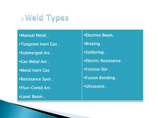
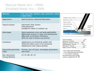
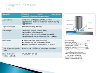
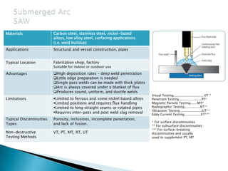
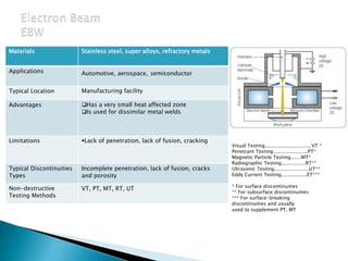
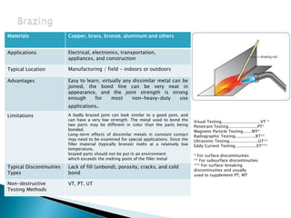
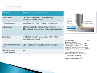
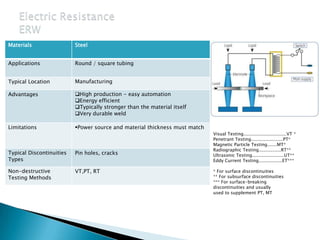
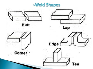
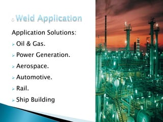
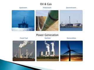
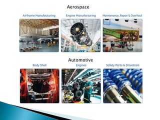
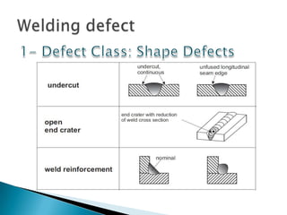
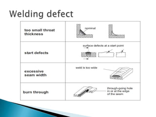
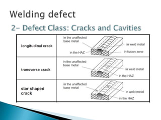
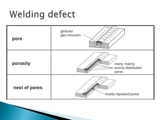
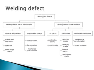


The document provides an extensive overview of various welding processes, their applications, advantages, limitations, and typical defects associated with them. It covers techniques such as electron beam welding, ultrasonic welding, and soldering, detailing their specific uses in industries like aerospace, automotive, and construction. Additionally, it highlights the importance of non-destructive testing methods for quality control in welds and addresses common welding defects and their causes.