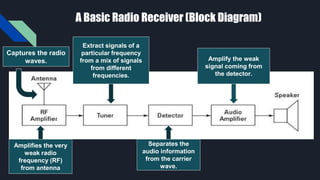
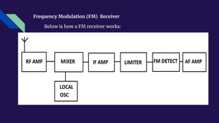
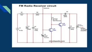
Typical
Receiver
Circuits
OBJECTIVES:
This presentation opt to discuss the following
ideas:
❏ What is a Receiver?
❏ Important Functions of a Receiver
❏ Types of Typical Receiver Circuit
❏ AM and FM Receiver Circuits
What is a Receiver?
Receivers are devices that accept signals, such as radio waves, and convert
them (frequently with amplification) into a useful form. Examples are
telephone receivers, which transform electrical impulses into audio signals,
and radio or television receivers, which accept electromagnetic waves and
convert them into sound or television pictures.
Receiver is an electronic equipment which pick up the desired signal, reject
the unwanted signal and demodulate the carrier signal to get back the
original modulating signal.
Important Functions of Receivers
Receive the incoming
modulated carrier by
the antenna.
Select the wanted
signal and reject the
unwanted signal and
the noise.
Detection and
amplification of the
information signal
from the carrier.
A Basic Radio Receiver (Block Diagram)
Captures the radio
waves.
Amplifies the very
weak radio
frequency (RF)
from antenna
Extract signals of a
particular frequency
from a mix of signals
from different
frequencies.
Separates the
audio information
from the carrier
wave.
Amplify the weak
signal coming from
the detector.
Types of Typical Receiver Circuits
● The RF amplifier, also called a low-noise amplifier (LNA),
processes the very weak input signals, increasing their
amplitude prior to mixing
● Low-noise components are used to ensure a sufficiently
high S/N ratio.
● Selectively should be such that it effectively eliminates
images.
● The RF amplifier is typically a class A circuit that can be
configured with bipolar or field-effect transistors.
RF INPUT AMPLIFIER
● Most of the gain and selectivity in a superheterodyne
receiver are obtained in the IF amplifier.
● IF amplifiers are tuned class A circuits capable of providing
gain in the 10- and 30-dB range.
● Usually two or more IF amplifiers are used to provide
adequate receiver gain.
● Ferrite-core transformers are used for coupling between
stages.
IF AMPLIFIER
● Receiver gain is typically far greater than required for adequate
reception. Excessive gain usually causes the received signal to
be distorted and the transmitted information to be less
intelligible.
● Manual gain control can be achieved by using a potentiometer
in RF and IF stages.
● Receivers include volume control controls in audio circuits.
● AGC circuits are more effective in handling large signals and
give the receiver a very wide dynamic range.
AUTOMATIC GAIN CONTROL CIRCUITS
● A squelch circuit or muting circuit is found in most
communications receivers.
● The squelch is used to keep the receiver audio turned off
until a RF signal appears at the receiver input.
● In AM systems such as CB radios, the noise level is high and
can be very annoying.
● Squelch circuits provide a means of keeping the audio
amplifier turned off during the time that noise is received in
the background and enabling it when an RF signal appears
at the input.
SQUELCH CIRCUIT
● In new designs, virtually all receiver circuits are ICs.
● A complete receiver usually consists of three or four ICs,
plus coils, transformers, capacitors, and filters.
● Most modern receivers are contained on a single IC.
INTEGRATED CIRCUITS (ICs) IN
RECEIVERS
● IC receivers are typically broken down into three major
sections:
1. The tuner with RF amplifier, mixer, and local
oscillator
2. The IF section, with amplifiers, demodulator, and
AGC and muting circuits
3. The audio power amplifier
● The second and third sections are entirely implemented with
ICs. The tuner may or may not be, for often the LNA is separate.
INTEGRATED CIRCUITS (ICs) IN RECEIVERS
● The Motorola MC3363 FM receiver IC chip contains all receiver
circuit except for the audio power amplifier (a separate chip)
● It is designed to operate at frequencies up to about 200 MHz.
● It is widely used in cordless telephones, paging receivers, and
other portable applications.
● This dual-conversion receiver contains two mixers, two local
oscillators, a limiter, a quadrature detector, and squelch
circuits.
● The first local oscillator has a built-in varactor that allows it to
be controlled by an external frequency synthesizer.
SINGLE-IC FM
RECEIVER
Circuit Diagram
AM Receiver Circuit
● AM is a modulation strategy utilizes in electronic communication,
most normally for transmitting data through a radio carrier wave.
In amplitude modulation, the amplitude of the carrier wave
changes as per the message signal is transmitting.
● There are two stages of AM receiver which are RF and IF. Hence,
RF-to-IF receivers incorporates an oscillator with a variable
frequency (differs with RF carrier frequency).
● By tuning to the channel, you are tuning the nearby oscillator and
RF tunable channel at the equivalent time. All stations provide a
fixed carrier frequency for sufficient selectivity.
● The schematic that appeared above is a basic AM receiver circuit.
● It utilizes just a single transistor and a few other small electronic
components.
● In the respective circuit, the coil and 365pF variable capacitor
structure a main circuit. Which gets the signals through the
antenna which acts as a receiving wire.
● Afterward, the signal is then identifying by the OA91 diode.
Further, it amplified by the BC547 transistor.
● Curl is equivalent to 80 turns of 26 s.w.g. Enameled copper wire
twisted on an unfilled cardboard toilet paper roll or an offcut bit
of plastic waste funnel. You can try various coils with the coil
found in AM compact radios.
● A radio receiver comprises a Radio Frequency (RF) area, an RF-
to-IF converter (mixer), An Intermediate Frequency (IF) area, a
Demodulator, and an Audio speaker.
● For the demodulator to work with any radio signal, we convert
the carrier frequency of any radio signal to Intermediate
Frequency (IF). Radio receiver utilizes to optimize for that
frequency.
● An AM receiver detects amplitude fluctuations in the radio waves at
a specific frequency, at that point, amplification change in the
signal voltage to work an amplifier or headphone.
Application and Uses of AM Receiver
FM Receiver Circuit
● Many radios might have a band switch that says something
like ”FM, MW, and SW.” This is really a mistake carried
forward by history since the advent of FM, which is
transmitted at VHF (88 – 108MHz). It’s wrong because FM
(Frequency Modulation) describes a modulation method
while MW and SW (Medium Wave and Short Wave) describe
a wavelength.
● MW and SW were the main broadcast radio bands until the
advent of FM. But FM became widely used to offer a far
superior noise immunity.
Frequency Modulation (FM) Receiver
Below is how a FM receiver works:
● The FM VHF signal is picked up by the antenna, as we discussed in
the previous FM transmitter article, and this is best as a quarter
wavelength. The RF amp is a VHF amplifier tuned to the FM band
and provides rejection to other frequencies and the IF image
(more on this just now).
● Then follows the mixer, which mixes this incoming frequency
with another one coming from the local oscillator. This is the
tuning part, and the result of this is the creation of two new
frequencies—the incoming signal plus and minus the local
oscillator (LO) frequency. One of these is the needed intermediate
frequency or IF.
● Commonly used in radio and television receivers.
● Mainly used for radio communications.
Application and Uses of FM Receiver
AM Receivers VS FM Receivers
Radio stations in the MW and SW bands transmit their material using
Amplitude Modulation (AM). This means that the transmitter radio (or
carrier) signal is modulated with the music or speech content so that the
carrier’s amplitude is varied about the incoming speech or music. AM is also
used on all aircraft radios from 108 to 136MHz.
On the other hand, FM allows the audio (music or speech) to shift or
modulate the high-frequency carrier up and down very lightly in frequency
while keeping the amplitude constant. The big advantage of this is that in a
complex FM receiver, the incoming carrier signal is greatly amplified
beyond clipping or limiting, so any amplitude noise component is lost. The
music is recovered without an amplitude (noise) component in an FM
demodulator.
Typical Type Receiver Example Solution
https://youtu.be/s9_vbeWmUA0
FM Reciever Circuit Finally Explained
https://youtu.be/2cp60CQwdlM
Supplementary Videos:
REFERENCES:
Britannica, T. Editors of Encyclopedia (2010). Receiver. Encyclopedia Britannica. Retrieved from
https://www.britannica.com/technology/receiver.
Block Diagram of FM Receiver youtube. (2020). (Video). YouTube. Retrieved from
https://www.youtube.com/watch?v=Q9Iy6FBN8UQ.
www.vedantu.com (2020). The functions of a radio receiver. Retrieved from
https://www.vedantu.com/question-answer/the-functions-of-a-radio-receiver-
are-a-receive-class-12-physics-cbse-5f8b45f44885cc7bcb3bc469
AM-FM. Retrieved from https://www.egr.msu.edu/~aviyente/AM-FM.pdf
D. Prabakaran, July 26, 2021. Simple FM Receiver. Retrieved from
https://www.electronicsforu.com/electronics-projects/simple-fm-receiver
Lambert G. What are FM Receivers? Circuit Basics. Retrieved from
https://www.circuitbasics.com/what-are-fm-receivers/
RF Wireless World. Retrieved from https://www.rfwireless-world.com/Terminology/AM-receiver-vs-
FM-receiver.html
Shajahan S, May 29, 2020. Simple AM Receiver Circuit. Circuits DIY. Retrieved from https://circuits-
diy.com/simple-am-receiver-circuit/
Radio Electronics: Transmitters and Receivers. (2016b, March 26). Dummies. Retrieved from
https://www.dummies.com/programming/electronics/components/radio-electronics-transmitters-and-
receivers/

TYPICAL RECEIVER CIRCUITS.pptx

  • 1.
  • 2.
    OBJECTIVES: This presentation optto discuss the following ideas: ❏ What is a Receiver? ❏ Important Functions of a Receiver ❏ Types of Typical Receiver Circuit ❏ AM and FM Receiver Circuits
  • 3.
    What is aReceiver? Receivers are devices that accept signals, such as radio waves, and convert them (frequently with amplification) into a useful form. Examples are telephone receivers, which transform electrical impulses into audio signals, and radio or television receivers, which accept electromagnetic waves and convert them into sound or television pictures. Receiver is an electronic equipment which pick up the desired signal, reject the unwanted signal and demodulate the carrier signal to get back the original modulating signal.
  • 4.
    Important Functions ofReceivers Receive the incoming modulated carrier by the antenna. Select the wanted signal and reject the unwanted signal and the noise. Detection and amplification of the information signal from the carrier.
  • 5.
    A Basic RadioReceiver (Block Diagram) Captures the radio waves. Amplifies the very weak radio frequency (RF) from antenna Extract signals of a particular frequency from a mix of signals from different frequencies. Separates the audio information from the carrier wave. Amplify the weak signal coming from the detector.
  • 6.
    Types of TypicalReceiver Circuits ● The RF amplifier, also called a low-noise amplifier (LNA), processes the very weak input signals, increasing their amplitude prior to mixing ● Low-noise components are used to ensure a sufficiently high S/N ratio. ● Selectively should be such that it effectively eliminates images. ● The RF amplifier is typically a class A circuit that can be configured with bipolar or field-effect transistors. RF INPUT AMPLIFIER
  • 7.
    ● Most ofthe gain and selectivity in a superheterodyne receiver are obtained in the IF amplifier. ● IF amplifiers are tuned class A circuits capable of providing gain in the 10- and 30-dB range. ● Usually two or more IF amplifiers are used to provide adequate receiver gain. ● Ferrite-core transformers are used for coupling between stages. IF AMPLIFIER
  • 8.
    ● Receiver gainis typically far greater than required for adequate reception. Excessive gain usually causes the received signal to be distorted and the transmitted information to be less intelligible. ● Manual gain control can be achieved by using a potentiometer in RF and IF stages. ● Receivers include volume control controls in audio circuits. ● AGC circuits are more effective in handling large signals and give the receiver a very wide dynamic range. AUTOMATIC GAIN CONTROL CIRCUITS
  • 9.
    ● A squelchcircuit or muting circuit is found in most communications receivers. ● The squelch is used to keep the receiver audio turned off until a RF signal appears at the receiver input. ● In AM systems such as CB radios, the noise level is high and can be very annoying. ● Squelch circuits provide a means of keeping the audio amplifier turned off during the time that noise is received in the background and enabling it when an RF signal appears at the input. SQUELCH CIRCUIT
  • 10.
    ● In newdesigns, virtually all receiver circuits are ICs. ● A complete receiver usually consists of three or four ICs, plus coils, transformers, capacitors, and filters. ● Most modern receivers are contained on a single IC. INTEGRATED CIRCUITS (ICs) IN RECEIVERS
  • 11.
    ● IC receiversare typically broken down into three major sections: 1. The tuner with RF amplifier, mixer, and local oscillator 2. The IF section, with amplifiers, demodulator, and AGC and muting circuits 3. The audio power amplifier ● The second and third sections are entirely implemented with ICs. The tuner may or may not be, for often the LNA is separate. INTEGRATED CIRCUITS (ICs) IN RECEIVERS
  • 12.
    ● The MotorolaMC3363 FM receiver IC chip contains all receiver circuit except for the audio power amplifier (a separate chip) ● It is designed to operate at frequencies up to about 200 MHz. ● It is widely used in cordless telephones, paging receivers, and other portable applications. ● This dual-conversion receiver contains two mixers, two local oscillators, a limiter, a quadrature detector, and squelch circuits. ● The first local oscillator has a built-in varactor that allows it to be controlled by an external frequency synthesizer. SINGLE-IC FM RECEIVER
  • 13.
  • 14.
    AM Receiver Circuit ●AM is a modulation strategy utilizes in electronic communication, most normally for transmitting data through a radio carrier wave. In amplitude modulation, the amplitude of the carrier wave changes as per the message signal is transmitting. ● There are two stages of AM receiver which are RF and IF. Hence, RF-to-IF receivers incorporates an oscillator with a variable frequency (differs with RF carrier frequency). ● By tuning to the channel, you are tuning the nearby oscillator and RF tunable channel at the equivalent time. All stations provide a fixed carrier frequency for sufficient selectivity.
  • 16.
    ● The schematicthat appeared above is a basic AM receiver circuit. ● It utilizes just a single transistor and a few other small electronic components. ● In the respective circuit, the coil and 365pF variable capacitor structure a main circuit. Which gets the signals through the antenna which acts as a receiving wire. ● Afterward, the signal is then identifying by the OA91 diode. Further, it amplified by the BC547 transistor. ● Curl is equivalent to 80 turns of 26 s.w.g. Enameled copper wire twisted on an unfilled cardboard toilet paper roll or an offcut bit of plastic waste funnel. You can try various coils with the coil found in AM compact radios.
  • 17.
    ● A radioreceiver comprises a Radio Frequency (RF) area, an RF- to-IF converter (mixer), An Intermediate Frequency (IF) area, a Demodulator, and an Audio speaker. ● For the demodulator to work with any radio signal, we convert the carrier frequency of any radio signal to Intermediate Frequency (IF). Radio receiver utilizes to optimize for that frequency.
  • 18.
    ● An AMreceiver detects amplitude fluctuations in the radio waves at a specific frequency, at that point, amplification change in the signal voltage to work an amplifier or headphone. Application and Uses of AM Receiver
  • 19.
    FM Receiver Circuit ●Many radios might have a band switch that says something like ”FM, MW, and SW.” This is really a mistake carried forward by history since the advent of FM, which is transmitted at VHF (88 – 108MHz). It’s wrong because FM (Frequency Modulation) describes a modulation method while MW and SW (Medium Wave and Short Wave) describe a wavelength. ● MW and SW were the main broadcast radio bands until the advent of FM. But FM became widely used to offer a far superior noise immunity.
  • 20.
    Frequency Modulation (FM)Receiver Below is how a FM receiver works:
  • 21.
    ● The FMVHF signal is picked up by the antenna, as we discussed in the previous FM transmitter article, and this is best as a quarter wavelength. The RF amp is a VHF amplifier tuned to the FM band and provides rejection to other frequencies and the IF image (more on this just now). ● Then follows the mixer, which mixes this incoming frequency with another one coming from the local oscillator. This is the tuning part, and the result of this is the creation of two new frequencies—the incoming signal plus and minus the local oscillator (LO) frequency. One of these is the needed intermediate frequency or IF.
  • 22.
    ● Commonly usedin radio and television receivers. ● Mainly used for radio communications. Application and Uses of FM Receiver
  • 24.
    AM Receivers VSFM Receivers Radio stations in the MW and SW bands transmit their material using Amplitude Modulation (AM). This means that the transmitter radio (or carrier) signal is modulated with the music or speech content so that the carrier’s amplitude is varied about the incoming speech or music. AM is also used on all aircraft radios from 108 to 136MHz. On the other hand, FM allows the audio (music or speech) to shift or modulate the high-frequency carrier up and down very lightly in frequency while keeping the amplitude constant. The big advantage of this is that in a complex FM receiver, the incoming carrier signal is greatly amplified beyond clipping or limiting, so any amplitude noise component is lost. The music is recovered without an amplitude (noise) component in an FM demodulator.
  • 25.
    Typical Type ReceiverExample Solution https://youtu.be/s9_vbeWmUA0 FM Reciever Circuit Finally Explained https://youtu.be/2cp60CQwdlM Supplementary Videos:
  • 26.
    REFERENCES: Britannica, T. Editorsof Encyclopedia (2010). Receiver. Encyclopedia Britannica. Retrieved from https://www.britannica.com/technology/receiver. Block Diagram of FM Receiver youtube. (2020). (Video). YouTube. Retrieved from https://www.youtube.com/watch?v=Q9Iy6FBN8UQ. www.vedantu.com (2020). The functions of a radio receiver. Retrieved from https://www.vedantu.com/question-answer/the-functions-of-a-radio-receiver- are-a-receive-class-12-physics-cbse-5f8b45f44885cc7bcb3bc469 AM-FM. Retrieved from https://www.egr.msu.edu/~aviyente/AM-FM.pdf D. Prabakaran, July 26, 2021. Simple FM Receiver. Retrieved from https://www.electronicsforu.com/electronics-projects/simple-fm-receiver Lambert G. What are FM Receivers? Circuit Basics. Retrieved from https://www.circuitbasics.com/what-are-fm-receivers/ RF Wireless World. Retrieved from https://www.rfwireless-world.com/Terminology/AM-receiver-vs- FM-receiver.html Shajahan S, May 29, 2020. Simple AM Receiver Circuit. Circuits DIY. Retrieved from https://circuits- diy.com/simple-am-receiver-circuit/
  • 27.
    Radio Electronics: Transmittersand Receivers. (2016b, March 26). Dummies. Retrieved from https://www.dummies.com/programming/electronics/components/radio-electronics-transmitters-and- receivers/