Download to read offline


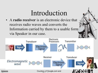
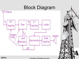
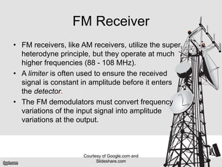
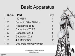
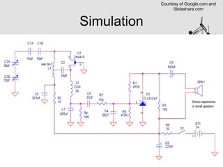


This document discusses the design and components of an FM radio receiver. It includes sections on the introduction, block diagram, history, FM receiver design, basic apparatus used, simulation, and operating frequency range. The history section notes that the first radio receiver was developed in 1896 by Alexander Stepanovich Popov, based on electromagnetic waves proven to exist by James Clerk Maxwell in 1887. The FM receiver section explains that FM receivers utilize the superheterodyne principle at higher frequencies between 88-108 MHz, with a limiter to ensure a constant signal amplitude before detection and FM demodulators to convert frequency variations to amplitude variations at the output.


