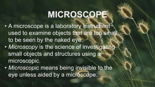
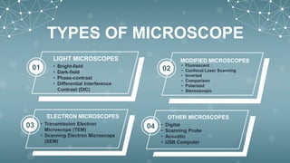
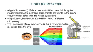
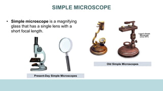
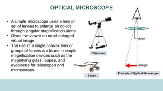
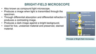
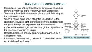
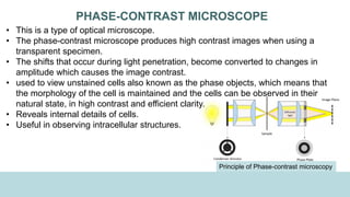
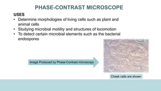
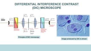
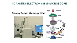
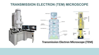
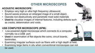
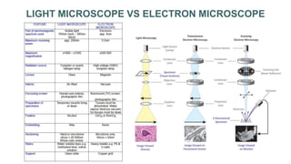
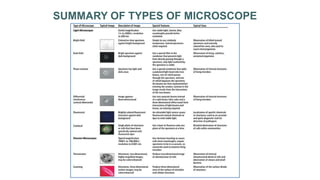
TYPES OF MICROSCOPE
& THEIR USES
MADE BY: AMAL MERAJ
HISTORY OF MICROSCOPE
PRINCIPLES OF MICROSCOPY
TYPES OF MICROSCOPE
LIGHT MICROSCOPE vs ELECTRON
MICROSCOPE
SUMMARY OF TYPES OF MICROSCOPES
01
02
03
04
05
CONTENTS
MICROSCOPE
• A microscope is a laboratory instrument
used to examine objects that are too small
to be seen by the naked eye.
• Microscopy is the science of investigating
small objects and structures using a
microscopic.
• Microscopic means being invisible to the
eye unless aided by a microscope.
HISTORY OF MICROSCOPE
• Zacharias Jansen (1580–1638) of Holland invented a compound light
microscope, one that used two lenses, with the second lens further
magnifying the image produced by the first.
• Englishman Robert Hooke (1635–1703) further refined the compound
microscope, adding such features as a stage to hold the specimen, an
illuminator, and coarse and fine focus controls. Until 1800, compound
microscopes designed by Hooke and others were limited to magnifications
of 30x to 50x, and their images exhibited aberrations.
• Carl Zeiss (1816–1888) and Ernst Abbe (1840–1905) added the substage
condenser and developed superior lenses that greatly reduced chromatic
and spherical aberration, while permitting vastly improved resolution and
higher magnification.
HISTORY OF MICROSCOPE
• Physicist Ernst Ruska and the electrical engineer Max Knoll (1931)
developed the first prototype electron microscope which was capable of
four-hundred-power magnification.
• Ernst Lubcke of Siemens & Halske (1932) built and obtained images from a
prototype electron microscope, applying the concepts described in
Rudenberg's patent.
• Ruska (1933) built the first electron microscope that exceeded the
resolution attainable with an optical (light) microscope.
• Manfred von Ardenne (1937) pioneered the scanning electron microscope.
• Siemens (1939) produced a transmission electron microscope (TEM) in
1939.
HISTORY OF MICROSCOPE
• Antony van Leeuwenhoek was a Dutch
businessman and scientist
• in 1674, viewing a drop of rainwater, he
observed things moving which he called
"animalcules."
• First to experimented with microbes, using
single-lensed microscopes of his own design
invented in 1670.
• Magnified up to 200x and achieved twice the
resolution of the best compound microscopes
of his day, mainly because he crafted better
lenses.
Father of Microbiology
(1632–1723)
MICROSCOPE USED BY LEEUWENHOEK
REPLICA OF
LEEUWENHOEK’S
MICROSCOPE
Leeuwenhoek’s drawings of
animalcules
MAGNIFICATION
RESOLUTION
NUMERICAL APERTURE
ILLUMINATION
PRINCIPLES OF
MICROSCOPY
ABERRATION
01
02
03
04
05
MAGNIFICATION
• Magnification is the factor by
which an image appears to be
enlarged.
• It is dependent upon the
curvature and size of the lens.
• The image formed is enlarged
to a particular degree called
the “Power of Magnification”.
Magnifying Glass
Crystal Ball
RESOLUTION
• Resolution or Resolving Power is
the ability of a lens to show two
adjacent objects as discrete
entities.
• Degree to which detail in specimen
is retained in a magnified image
• The minimum distance between
two visible bodies at which they
can be seen as separate is the
“Limit of Resolution (LR)”.
• Resolution is best when LR is low.
• The shorter the wavelength of the
illumination, the better the
resolution.
Resolving Power (R.P) =
𝑊𝑎𝑣𝑒𝑙𝑒𝑛𝑔𝑡ℎ 𝑜𝑓 𝑙𝑖𝑔ℎ𝑡 𝑖𝑛 𝑛𝑚
2 x 𝑁𝑢𝑚𝑒𝑟𝑖𝑐𝑎𝑙 𝐴𝑝𝑒𝑟𝑡𝑢𝑟𝑒
𝑜𝑓 𝑜𝑏𝑗𝑒𝑐𝑡𝑖𝑣𝑒 𝑙𝑒𝑛𝑠
NUMERICAL APERTURE
• The numerical aperture of
a microscope objective is a
measure of its ability to
gather light and resolve
fine specimen detail at a
fixed object.
• Each objective has a fixed
numerical aperture reading
• Higher the NA the better
will be the resolution.
• Greater the refractive index
(n) the greater will be the
NA.
ILLUMINATION
• Effective illumination is required for efficient
magnification and resolving power.
• Artificial light from a tungsten lamp is the
most commonly used light source in
microscopy.
• Iris diaphragm regulates the amount of light
entering the condenser.
• Too much light can reduce contrast and burn
out the image.
• Other ways to increase contrast in cell
components are by using special lenses
(phase-contrast microscope) and by dyes.
ABERRATION
• Aberration is a property of optical systems such as
lenses that causes light to be spread out over some
region of space rather than focused to a point.
• Aberrations cause the image formed by a lens to be
blurred or distorted.
• Aberrations associated with microscope are spherical
aberration and chromatic aberration.
ABERRATION
• Creates a curved image rather than
flat.
SPHERICAL ABERRATION
Image formed by Spherical Aberration
ABERRATION
• Creates a blurry image like a rainbow
• Caused by the lens acting as a prism
• For correction- Achromatic objective
and Apochromatic objectives.
CHROMATIC ABERRATION
Image formed by Chromatic Aberration
TYPES OF MICROSCOPE
• Bright-field
• Dark-field
• Phase-contrast
• Differential Interference
Contrast (DIC)
LIGHT MICROSCOPES
01
• Transmission Electron
Microscope (TEM)
• Scanning Electron Microscope
(SEM)
ELECTRON MICROSCOPES
03
• Fluorescent
• Confocal Laser Scanning
• Inverted
• Comparison
• Polarized
• Stereoscopic
MODIFIED MICROSCOPES
02
• Digital
• Scanning Probe
• Acoustic
• USB Computer
OTHER MICROSCOPES
04
LIGHT MICROSCOPE
• A light microscope (LM) is an instrument that uses visible light and
magnifying lenses to examine small objects not visible to the naked
eye, or in finer detail than the naked eye allows.
• Magnification, however, is not the most important issue in
microscopy.
• The usefulness of any microscope is that it produces better
resolution than the eye.
SIMPLE MICROSCOPE
• Simple microscope is a magnifying
glass that has a single lens with a
short focal length.
Old Simple Microscopes
Present-Day Simple Microscopes
OPTICAL MICROSCOPE
• A simple microscope uses a lens or
set of lenses to enlarge an object
through angular magnification alone
• Gives the viewer an erect enlarged
virtual image.
• The use of a single convex lens or
groups of lenses are found in simple
magnification devices such as the
magnifying glass, loupes, and
eyepieces for telescopes and
microscopes.
Principle of Optical Microscope
Loupe
Telescope
COMPOUND MICROSCOPE
• Hooke devised the compound
microscope and illumination system
(1665).
• It was one of the best such
microscopes of his time.
Robert Hooke’s Micrographia
MODERN COMPOUND MICROSCOPE
PRINCIPLES OF COMPOUND MICROSCOPE
• The magnification from compound microscope
occurs in two series of lenses.
I. (i) The objective lens close to the object to be
observed.
II. (ii) the ocular lens or eyepiece; the one closest to
the eye.
• The objective lens produces an initial magnified ‘real
image’
• This image is again magnified by the ocular lens
(eyepiece) to obtain a final ‘virtual image’.
• This image is received by the eye and converted to a
retinal and visual image.
PRINCIPLES OF COMPOUND MICROSCOPE
• The total power of magnification of the
final image is formed by the combined
product of two separate powers of each
lens.
• It can magnify up to x2000.
• Structures less than 0.2um cannot be
resolved with the compound light
microscope.
BRIGHT-FIELD MICROSCOPE
• Also known as compound light microscope.
• Produces a image when light is transmitted through the
specimen.
• Through differential absorption and differential refraction it
produces a contrasting image.
• Produces a dark image against a bright background.
• Used for live, unstained material and preserved, stained
material.
Principle of Bright-field microscopy
BRIGHT-FIELD MICROSCOPE
USES
• Vastly used in Biology, Cellular
Biology, and Microbiological
Laboratory studies.
• It can be used to identify basic
bacteria cells and parasitic
protozoans such as Paramecium.
Image Produced by Bright-field microscopy
Bone marrow biopsies of cynomolgus monkeys experimentally infected
with hepatitis E virus at 160 dpi. Histological analysis showing: (A-B)
vacuolization in mononuclear cells (!); (C) lymphocyte proliferation and
activation clusters; (D) megakaryocytosis (>5 megakaryocytes/field); (E)
absence of megakaryocytosis (0-2 megakaryocytes/field); and (F)
vacuolization in endosteal cells (!). Hematoxilin and Eosin stain.
DARK-FIELD MICROSCOPE
• Specialized type of bright field light microscope which has
several similarities to the Phase-Contrast Microscope.
• To make a dark field Microscope place a dark-field stop to
the condenser lens.
• When a hollow cone beam of light is transmitted to the
specimen, deviated light (unreflected/unrefracted) rays do
not pass through the objectives but the undeviated
(reflected/refracted) light passes through the objectives to
the specimen forming an image.
• Resulting image is brightly illuminated surrounded by a
dark (black) field.
• It is used to visualize living cells which cannot be stained
or be distorted by drying.
Principle of Dark-field microscopy
DARK-FIELD MICROSCOPE
USES
• It is used to visualize the internal organs of larger cells such as the
eukaryotic cells
• Identification of bacterial cells with distinctive shapes such as Treponema
pallidum, a causative agent of syphilis.
Image Produced by Dark-field microscopy
Treponema pallidum bacteria (syphilis) is shown
PHASE-CONTRAST MICROSCOPE
• This is a type of optical microscope.
• The phase-contrast microscope produces high contrast images when using a
transparent specimen.
• The shifts that occur during light penetration, become converted to changes in
amplitude which causes the image contrast.
• used to view unstained cells also known as the phase objects, which means that
the morphology of the cell is maintained and the cells can be observed in their
natural state, in high contrast and efficient clarity.
• Reveals internal details of cells.
• Useful in observing intracellular structures.
Principle of Phase-contrast microscopy
PHASE-CONTRAST MICROSCOPE
USES
• Determine morphologies of living cells such as plant and
animal cells
• Studying microbial motility and structures of locomotion
• To detect certain microbial elements such as the bacterial
endospores
Image Produced by Phase-Contrast microscopy
Cheek cells are shown
DIFFERENTIAL INTERFERENCE CONTRAST
(DIC) MICROSCOPE
• Also known as Nomarski interference contrast (NIC) or Nomarski
microscopy.
• It is an optical microscopy technique.
• It has two prisms refinements which add contrasting colours to the images.
• Two beams of light instead of one.
• Produces well-defined images with detailed view.
• Creates a vividly coloured, three-dimensional image.
USES
• Visualizes live and unstained biological samples, such as a smear from a
tissue culture or individual water borne single-celled organisms.
DIFFERENTIAL INTERFERENCE CONTRAST
(DIC) MICROSCOPE
Image produced by DIC is shown
Principle of DIC microscopy
FLUORESCENCE MICROSCOPE
• Specially modified compound microscope.
• Uses a mercury arch lamp as a source of UV light.
• The microscope will also comprise excitation filter,
dichromatic mirror and an emission filter.
• Filter protects the viewer’s eye from UV rays.
• The specimen to be viewed is coated with dyes
(acridine, fluroscein) or minerals which show
fluorescence.
• Subsquent illumination by ultraviolet radiation causes
the specimen to give off light that forms its own image;
usually an intense yellow, orange or red against a black
field.
• An advantage of fluourescence microscopy is that it
can be used to detect and visualise multiple fluorescent
molecules e.g. cells glowing as they are doing their
work
Principle of Fluorescence microscopy
FLUORESCENCE MICROSCOPE
USES
• Visualization of bacterial agents such
as Mycobacterium tuberculosis.
• Identify specific antibodies produced against
bacterial antigens/pathogens in
immunofluorescence techniques by labeling the
antibodies with fluorochromes.
• Used in ecological studies to identify and
observe microorganisms labeled by the
fluorochromes.
• Differentiate between dead and live bacteria by
the color they emit when treated with special
stains.
Image produced by
fluorescence microscopy of
mycobacterium tuberculosis.
CONFOCAL LASER SCANNING MICROSCOPE
(CLSM)
• Laser beam used to illuminate spots on specimen.
• Laser beam focused and scanned over the sample
produces 3D and 2D images in the computer screen.
• Laser beam scans a single plane of 1 um thickness.
• Can scan many thin sections through the sample.
• Used on specimens which are too thick for a light
microscope.
Principle of CLSM
CONFOCAL LASER SCANNING MICROSCOPE
(CLSM)
USES
• Observing cellular
morphology in multilayered
specimen.
• Used in diagnosing CA
cervix.
• Evaluation and diagnosis
of basal cell or carcinoma
of skin. Confocal Laser Scanning Microscopy
image of dendritic cells
Confocal Laser Scanning Microscopy
image of Astrocyte Brain Cells
POLARIZED MICROSCOPE
• A polarizing microscope is an optical
microscope composed of a detector, lenses
and polarizing filters.
• It uses two polarizers.
• The polarizer is positioned at the light path
somewhere between the specimen and an
analyzer (second polarizer).
• Analyzer is placed in the optical pathway
between the objective rear aperture and the
observation tubes or camera port.
• Polarizers transmit one polarization angle of
light.
• Crossed polarizers transmit no light
Principle of Polarized Microscope
POLARIZED MICROSCOPE
USES
• Study of birefringent materials; materials
that split a beam of light into two.
• Used in crystallography, urine examination.
• Apple Green Birefringence in
AMYLOIDOSIS
Image of calcite crystal from polarized
microscope
INVERTED MICROSCOPE
• Used in metallurgy.
• Double microscope.
• Produces 2D and 3D images.
USES
• Examination of cultures in flat bottom
dishes.
• Micro dissection.
• Examination of parasites.
• Observation of agglutination in serology.
Inverted microscopic images of RBCs in human blood
showing hemolysis after treatment with G7 amine
terminated PAMAM dendrimers at dose of 10 mg/kg.
COMPARISON MICROSCOPE
• Observe two different objects at the same time.
• Used to compare objects..
• Composes of two independent objective lenses joined
together by an optical bridge to a common eyepiece
lens.
• Objects are observed side-by-side in a circular field
that is equally divided into two parts.
USES
• Examination of firearms.
• Used greatly in forensics applications for comparing
different traces.
Firearm comparison by
Comparison Microscope
STEREOSCOPIC MICROSCOPE
• Double microscope
• It is an optical microscope variant designed observation of
a sample.
• Low magnification and low resolution.
• Reflected illumination rather than transmitted one
• It uses two separate optical paths with two objectives and
eyepieces.
• Provides different angles for each eye to view.
• Gives a three-dimensional view of objects.
USES
• Dissections
• Forensic Applications for Questioned Document
Examinations such as comparison of texture and condition
of paper surfaces, ribbons, pen and pencil points, etc.
Image produced by
Stereoscopic Microscope
COMPARISONS OF LIGHT MICROSCOPES
ELECTRON MICROSCOPY
• Electron microscopy (EM) is a technique for obtaining
high resolution images of biological and non-biological
specimens.
• Uses a beam of accelerated electrons as a source of
illumination.
• The wave of electrons are 100,000 times shorter than
waves of visible light.
• EM images provide key information on the structural
basis of cell function and of cell disease.
• This microscopy can yield information about
topography, morphology, composition, and,
crystallographic structure.
SCANNING ELECTRON (SEM) MICROSCOPE
• SEM produces images by probing the specimen with a focused electron
beam that is scanned across a rectangular area of the specimen (raster
scanning).
• Doesn’t transmit electrons.
• Shower of electron deflected from the surface is picked up by a
sophisticated detector.
• The electron pattern displayed as an image on television screen.
• Produces an striking three-dimensional realistic images.
• Magnifies external surface of specimen.
SCANNING ELECTRON (SEM) MICROSCOPE
USES
• SEMs can be used in a variety of industrial, commercial, and research
applications.
• SEMs are used in materials science for research, quality control and failure
analysis.
• Just about any material science industry, from aerospace and chemistry to
electronics and energy usage, have only been made possible with the help of
SEMs.
• Criminal and other forensic investigations utilize SEMs to uncover evidence
and gain further insight.
• In biological sciences, SEMs can be used on anything from insects and animal
tissue to bacteria and viruses.
• Geological sampling using a scanning electron microscope can determine
weathering processes and morphology of the samples.
SCANNING ELECTRON (SEM) MICROSCOPE
Images produced by SEM
TRANSMISSION ELECTRON (TEM) MICROSCOPE
• Uses a high voltage electron beam to illuminate the specimen and create an
image.
• Transmits electron through the specimen.
• The image-recording system usually consists of a fluorescent screen for
viewing and focusing the image and a digital camera for permanent records.
• Electrons cannot readily penetrate thick preparations.
• The specimen must be sectioned into extremely thin slices (20-100nm thick)
and stained or coated with metals to increase image contrast.
• Creates a two-dimensional image.
• Sections of specimen are viewed under very high magnification
TRANSMISSION ELECTRON (TEM) MICROSCOPE
USES
• TEMs are ideal for a number of different fields such as life sciences,
nanotechnology, medical, biological and material research, forensic analysis,
gemology and metallurgy, and industry and education.
• TEMs provide topographical, morphological, compositional and crystalline
information.
• TEMs can be used in semiconductor analysis and production and the
manufacturing of computer and silicon chips.
• Colleges and universities can utilize TEMs for research and studies.
TRANSMISSION ELECTRON (TEM) MICROSCOPE
Images produced by TEM
OTHER MICROSCOPES
DIGITAL MICROSCOPE:
• Variation of a traditional optical microscope that uses optics and a digital
camera to output an image to a monitor sometimes by means of software
running on a computer.
• Efficient tool to inspect and analyze various objects from micro-fabricated
parts to large electronic devices.
• Used in a wide range of industries, such as education, research,
medicine, forensics, and industrial manufacturing.
SCANNING PROBE MICROSCOPE (SPM):
• Produces an image that represents the structure of surface rather than
direct view of surface.
• Used to make images of nanoscale surfaces and structures, including
atoms.
OTHER MICROSCOPES
ACOUSTIC MICROSCOPE:
• Employs very high or ultra high frequency ultrasound.
• Sound waves produce an enlarged image of a small object.
• Operate non-destructively and penetrate most solid materials
• Used to visualize images of internal features, including defects such
as cracks, delamination and voids.
USB COMPUTER MICROSCOPE (SPM):
• Low-powered digital microscope which connects to a computer,
normally via a USB port.
• Used in examination of flat objects like coins, circuit boards,
banknotes.
• Examining irregular surfaces such as fibers with a high depth of field.
• Examining large items in situ when conventional microscopes can not
be used.
LIGHT MICROSCOPE VS ELECTRON MICROSCOPE
SUMMARY OF TYPES OF MICROSCOPE
THANK YOU

Types of Microscope

  • 1.
    TYPES OF MICROSCOPE &THEIR USES MADE BY: AMAL MERAJ
  • 2.
    HISTORY OF MICROSCOPE PRINCIPLESOF MICROSCOPY TYPES OF MICROSCOPE LIGHT MICROSCOPE vs ELECTRON MICROSCOPE SUMMARY OF TYPES OF MICROSCOPES 01 02 03 04 05 CONTENTS
  • 3.
    MICROSCOPE • A microscopeis a laboratory instrument used to examine objects that are too small to be seen by the naked eye. • Microscopy is the science of investigating small objects and structures using a microscopic. • Microscopic means being invisible to the eye unless aided by a microscope.
  • 4.
    HISTORY OF MICROSCOPE •Zacharias Jansen (1580–1638) of Holland invented a compound light microscope, one that used two lenses, with the second lens further magnifying the image produced by the first. • Englishman Robert Hooke (1635–1703) further refined the compound microscope, adding such features as a stage to hold the specimen, an illuminator, and coarse and fine focus controls. Until 1800, compound microscopes designed by Hooke and others were limited to magnifications of 30x to 50x, and their images exhibited aberrations. • Carl Zeiss (1816–1888) and Ernst Abbe (1840–1905) added the substage condenser and developed superior lenses that greatly reduced chromatic and spherical aberration, while permitting vastly improved resolution and higher magnification.
  • 5.
    HISTORY OF MICROSCOPE •Physicist Ernst Ruska and the electrical engineer Max Knoll (1931) developed the first prototype electron microscope which was capable of four-hundred-power magnification. • Ernst Lubcke of Siemens & Halske (1932) built and obtained images from a prototype electron microscope, applying the concepts described in Rudenberg's patent. • Ruska (1933) built the first electron microscope that exceeded the resolution attainable with an optical (light) microscope. • Manfred von Ardenne (1937) pioneered the scanning electron microscope. • Siemens (1939) produced a transmission electron microscope (TEM) in 1939.
  • 6.
    HISTORY OF MICROSCOPE •Antony van Leeuwenhoek was a Dutch businessman and scientist • in 1674, viewing a drop of rainwater, he observed things moving which he called "animalcules." • First to experimented with microbes, using single-lensed microscopes of his own design invented in 1670. • Magnified up to 200x and achieved twice the resolution of the best compound microscopes of his day, mainly because he crafted better lenses. Father of Microbiology (1632–1723)
  • 7.
    MICROSCOPE USED BYLEEUWENHOEK REPLICA OF LEEUWENHOEK’S MICROSCOPE Leeuwenhoek’s drawings of animalcules
  • 8.
  • 9.
    MAGNIFICATION • Magnification isthe factor by which an image appears to be enlarged. • It is dependent upon the curvature and size of the lens. • The image formed is enlarged to a particular degree called the “Power of Magnification”. Magnifying Glass Crystal Ball
  • 10.
    RESOLUTION • Resolution orResolving Power is the ability of a lens to show two adjacent objects as discrete entities. • Degree to which detail in specimen is retained in a magnified image • The minimum distance between two visible bodies at which they can be seen as separate is the “Limit of Resolution (LR)”. • Resolution is best when LR is low. • The shorter the wavelength of the illumination, the better the resolution. Resolving Power (R.P) = 𝑊𝑎𝑣𝑒𝑙𝑒𝑛𝑔𝑡ℎ 𝑜𝑓 𝑙𝑖𝑔ℎ𝑡 𝑖𝑛 𝑛𝑚 2 x 𝑁𝑢𝑚𝑒𝑟𝑖𝑐𝑎𝑙 𝐴𝑝𝑒𝑟𝑡𝑢𝑟𝑒 𝑜𝑓 𝑜𝑏𝑗𝑒𝑐𝑡𝑖𝑣𝑒 𝑙𝑒𝑛𝑠
  • 11.
    NUMERICAL APERTURE • Thenumerical aperture of a microscope objective is a measure of its ability to gather light and resolve fine specimen detail at a fixed object. • Each objective has a fixed numerical aperture reading • Higher the NA the better will be the resolution. • Greater the refractive index (n) the greater will be the NA.
  • 12.
    ILLUMINATION • Effective illuminationis required for efficient magnification and resolving power. • Artificial light from a tungsten lamp is the most commonly used light source in microscopy. • Iris diaphragm regulates the amount of light entering the condenser. • Too much light can reduce contrast and burn out the image. • Other ways to increase contrast in cell components are by using special lenses (phase-contrast microscope) and by dyes.
  • 13.
    ABERRATION • Aberration isa property of optical systems such as lenses that causes light to be spread out over some region of space rather than focused to a point. • Aberrations cause the image formed by a lens to be blurred or distorted. • Aberrations associated with microscope are spherical aberration and chromatic aberration.
  • 14.
    ABERRATION • Creates acurved image rather than flat. SPHERICAL ABERRATION SPHERICAL ABERRATION Image formed by Spherical Aberration
  • 15.
    ABERRATION • Creates ablurry image like a rainbow • Caused by the lens acting as a prism • For correction- Achromatic objective and Apochromatic objectives. CHROMATIC ABERRATION Image formed by Chromatic Aberration
  • 16.
    TYPES OF MICROSCOPE •Bright-field • Dark-field • Phase-contrast • Differential Interference Contrast (DIC) LIGHT MICROSCOPES 01 • Transmission Electron Microscope (TEM) • Scanning Electron Microscope (SEM) ELECTRON MICROSCOPES 03 • Fluorescent • Confocal Laser Scanning • Inverted • Comparison • Polarized • Stereoscopic MODIFIED MICROSCOPES 02 • Digital • Scanning Probe • Acoustic • USB Computer OTHER MICROSCOPES 04
  • 17.
    LIGHT MICROSCOPE • Alight microscope (LM) is an instrument that uses visible light and magnifying lenses to examine small objects not visible to the naked eye, or in finer detail than the naked eye allows. • Magnification, however, is not the most important issue in microscopy. • The usefulness of any microscope is that it produces better resolution than the eye.
  • 18.
    SIMPLE MICROSCOPE • Simplemicroscope is a magnifying glass that has a single lens with a short focal length. Old Simple Microscopes Present-Day Simple Microscopes
  • 19.
    OPTICAL MICROSCOPE • Asimple microscope uses a lens or set of lenses to enlarge an object through angular magnification alone • Gives the viewer an erect enlarged virtual image. • The use of a single convex lens or groups of lenses are found in simple magnification devices such as the magnifying glass, loupes, and eyepieces for telescopes and microscopes. Principle of Optical Microscope Loupe Telescope
  • 20.
    COMPOUND MICROSCOPE • Hookedevised the compound microscope and illumination system (1665). • It was one of the best such microscopes of his time. Robert Hooke’s Micrographia
  • 21.
  • 22.
    PRINCIPLES OF COMPOUNDMICROSCOPE • The magnification from compound microscope occurs in two series of lenses. I. (i) The objective lens close to the object to be observed. II. (ii) the ocular lens or eyepiece; the one closest to the eye. • The objective lens produces an initial magnified ‘real image’ • This image is again magnified by the ocular lens (eyepiece) to obtain a final ‘virtual image’. • This image is received by the eye and converted to a retinal and visual image.
  • 23.
    PRINCIPLES OF COMPOUNDMICROSCOPE • The total power of magnification of the final image is formed by the combined product of two separate powers of each lens. • It can magnify up to x2000. • Structures less than 0.2um cannot be resolved with the compound light microscope.
  • 24.
    BRIGHT-FIELD MICROSCOPE • Alsoknown as compound light microscope. • Produces a image when light is transmitted through the specimen. • Through differential absorption and differential refraction it produces a contrasting image. • Produces a dark image against a bright background. • Used for live, unstained material and preserved, stained material. Principle of Bright-field microscopy
  • 25.
    BRIGHT-FIELD MICROSCOPE USES • Vastlyused in Biology, Cellular Biology, and Microbiological Laboratory studies. • It can be used to identify basic bacteria cells and parasitic protozoans such as Paramecium. Image Produced by Bright-field microscopy Bone marrow biopsies of cynomolgus monkeys experimentally infected with hepatitis E virus at 160 dpi. Histological analysis showing: (A-B) vacuolization in mononuclear cells (!); (C) lymphocyte proliferation and activation clusters; (D) megakaryocytosis (>5 megakaryocytes/field); (E) absence of megakaryocytosis (0-2 megakaryocytes/field); and (F) vacuolization in endosteal cells (!). Hematoxilin and Eosin stain.
  • 26.
    DARK-FIELD MICROSCOPE • Specializedtype of bright field light microscope which has several similarities to the Phase-Contrast Microscope. • To make a dark field Microscope place a dark-field stop to the condenser lens. • When a hollow cone beam of light is transmitted to the specimen, deviated light (unreflected/unrefracted) rays do not pass through the objectives but the undeviated (reflected/refracted) light passes through the objectives to the specimen forming an image. • Resulting image is brightly illuminated surrounded by a dark (black) field. • It is used to visualize living cells which cannot be stained or be distorted by drying. Principle of Dark-field microscopy
  • 27.
    DARK-FIELD MICROSCOPE USES • Itis used to visualize the internal organs of larger cells such as the eukaryotic cells • Identification of bacterial cells with distinctive shapes such as Treponema pallidum, a causative agent of syphilis. Image Produced by Dark-field microscopy Treponema pallidum bacteria (syphilis) is shown
  • 28.
    PHASE-CONTRAST MICROSCOPE • Thisis a type of optical microscope. • The phase-contrast microscope produces high contrast images when using a transparent specimen. • The shifts that occur during light penetration, become converted to changes in amplitude which causes the image contrast. • used to view unstained cells also known as the phase objects, which means that the morphology of the cell is maintained and the cells can be observed in their natural state, in high contrast and efficient clarity. • Reveals internal details of cells. • Useful in observing intracellular structures. Principle of Phase-contrast microscopy
  • 29.
    PHASE-CONTRAST MICROSCOPE USES • Determinemorphologies of living cells such as plant and animal cells • Studying microbial motility and structures of locomotion • To detect certain microbial elements such as the bacterial endospores Image Produced by Phase-Contrast microscopy Cheek cells are shown
  • 30.
    DIFFERENTIAL INTERFERENCE CONTRAST (DIC)MICROSCOPE • Also known as Nomarski interference contrast (NIC) or Nomarski microscopy. • It is an optical microscopy technique. • It has two prisms refinements which add contrasting colours to the images. • Two beams of light instead of one. • Produces well-defined images with detailed view. • Creates a vividly coloured, three-dimensional image. USES • Visualizes live and unstained biological samples, such as a smear from a tissue culture or individual water borne single-celled organisms.
  • 31.
    DIFFERENTIAL INTERFERENCE CONTRAST (DIC)MICROSCOPE Image produced by DIC is shown Principle of DIC microscopy
  • 32.
    FLUORESCENCE MICROSCOPE • Speciallymodified compound microscope. • Uses a mercury arch lamp as a source of UV light. • The microscope will also comprise excitation filter, dichromatic mirror and an emission filter. • Filter protects the viewer’s eye from UV rays. • The specimen to be viewed is coated with dyes (acridine, fluroscein) or minerals which show fluorescence. • Subsquent illumination by ultraviolet radiation causes the specimen to give off light that forms its own image; usually an intense yellow, orange or red against a black field. • An advantage of fluourescence microscopy is that it can be used to detect and visualise multiple fluorescent molecules e.g. cells glowing as they are doing their work Principle of Fluorescence microscopy
  • 33.
    FLUORESCENCE MICROSCOPE USES • Visualizationof bacterial agents such as Mycobacterium tuberculosis. • Identify specific antibodies produced against bacterial antigens/pathogens in immunofluorescence techniques by labeling the antibodies with fluorochromes. • Used in ecological studies to identify and observe microorganisms labeled by the fluorochromes. • Differentiate between dead and live bacteria by the color they emit when treated with special stains. Image produced by fluorescence microscopy of mycobacterium tuberculosis.
  • 34.
    CONFOCAL LASER SCANNINGMICROSCOPE (CLSM) • Laser beam used to illuminate spots on specimen. • Laser beam focused and scanned over the sample produces 3D and 2D images in the computer screen. • Laser beam scans a single plane of 1 um thickness. • Can scan many thin sections through the sample. • Used on specimens which are too thick for a light microscope. Principle of CLSM
  • 35.
    CONFOCAL LASER SCANNINGMICROSCOPE (CLSM) USES • Observing cellular morphology in multilayered specimen. • Used in diagnosing CA cervix. • Evaluation and diagnosis of basal cell or carcinoma of skin. Confocal Laser Scanning Microscopy image of dendritic cells Confocal Laser Scanning Microscopy image of Astrocyte Brain Cells
  • 36.
    POLARIZED MICROSCOPE • Apolarizing microscope is an optical microscope composed of a detector, lenses and polarizing filters. • It uses two polarizers. • The polarizer is positioned at the light path somewhere between the specimen and an analyzer (second polarizer). • Analyzer is placed in the optical pathway between the objective rear aperture and the observation tubes or camera port. • Polarizers transmit one polarization angle of light. • Crossed polarizers transmit no light Principle of Polarized Microscope
  • 37.
    POLARIZED MICROSCOPE USES • Studyof birefringent materials; materials that split a beam of light into two. • Used in crystallography, urine examination. • Apple Green Birefringence in AMYLOIDOSIS Image of calcite crystal from polarized microscope
  • 38.
    INVERTED MICROSCOPE • Usedin metallurgy. • Double microscope. • Produces 2D and 3D images. USES • Examination of cultures in flat bottom dishes. • Micro dissection. • Examination of parasites. • Observation of agglutination in serology. Inverted microscopic images of RBCs in human blood showing hemolysis after treatment with G7 amine terminated PAMAM dendrimers at dose of 10 mg/kg.
  • 39.
    COMPARISON MICROSCOPE • Observetwo different objects at the same time. • Used to compare objects.. • Composes of two independent objective lenses joined together by an optical bridge to a common eyepiece lens. • Objects are observed side-by-side in a circular field that is equally divided into two parts. USES • Examination of firearms. • Used greatly in forensics applications for comparing different traces. Firearm comparison by Comparison Microscope
  • 40.
    STEREOSCOPIC MICROSCOPE • Doublemicroscope • It is an optical microscope variant designed observation of a sample. • Low magnification and low resolution. • Reflected illumination rather than transmitted one • It uses two separate optical paths with two objectives and eyepieces. • Provides different angles for each eye to view. • Gives a three-dimensional view of objects. USES • Dissections • Forensic Applications for Questioned Document Examinations such as comparison of texture and condition of paper surfaces, ribbons, pen and pencil points, etc. Image produced by Stereoscopic Microscope
  • 41.
  • 42.
    ELECTRON MICROSCOPY • Electronmicroscopy (EM) is a technique for obtaining high resolution images of biological and non-biological specimens. • Uses a beam of accelerated electrons as a source of illumination. • The wave of electrons are 100,000 times shorter than waves of visible light. • EM images provide key information on the structural basis of cell function and of cell disease. • This microscopy can yield information about topography, morphology, composition, and, crystallographic structure.
  • 43.
    SCANNING ELECTRON (SEM)MICROSCOPE • SEM produces images by probing the specimen with a focused electron beam that is scanned across a rectangular area of the specimen (raster scanning). • Doesn’t transmit electrons. • Shower of electron deflected from the surface is picked up by a sophisticated detector. • The electron pattern displayed as an image on television screen. • Produces an striking three-dimensional realistic images. • Magnifies external surface of specimen.
  • 44.
  • 45.
    SCANNING ELECTRON (SEM)MICROSCOPE USES • SEMs can be used in a variety of industrial, commercial, and research applications. • SEMs are used in materials science for research, quality control and failure analysis. • Just about any material science industry, from aerospace and chemistry to electronics and energy usage, have only been made possible with the help of SEMs. • Criminal and other forensic investigations utilize SEMs to uncover evidence and gain further insight. • In biological sciences, SEMs can be used on anything from insects and animal tissue to bacteria and viruses. • Geological sampling using a scanning electron microscope can determine weathering processes and morphology of the samples.
  • 46.
    SCANNING ELECTRON (SEM)MICROSCOPE Images produced by SEM
  • 47.
    TRANSMISSION ELECTRON (TEM)MICROSCOPE • Uses a high voltage electron beam to illuminate the specimen and create an image. • Transmits electron through the specimen. • The image-recording system usually consists of a fluorescent screen for viewing and focusing the image and a digital camera for permanent records. • Electrons cannot readily penetrate thick preparations. • The specimen must be sectioned into extremely thin slices (20-100nm thick) and stained or coated with metals to increase image contrast. • Creates a two-dimensional image. • Sections of specimen are viewed under very high magnification
  • 48.
  • 49.
    TRANSMISSION ELECTRON (TEM)MICROSCOPE USES • TEMs are ideal for a number of different fields such as life sciences, nanotechnology, medical, biological and material research, forensic analysis, gemology and metallurgy, and industry and education. • TEMs provide topographical, morphological, compositional and crystalline information. • TEMs can be used in semiconductor analysis and production and the manufacturing of computer and silicon chips. • Colleges and universities can utilize TEMs for research and studies.
  • 50.
    TRANSMISSION ELECTRON (TEM)MICROSCOPE Images produced by TEM
  • 51.
    OTHER MICROSCOPES DIGITAL MICROSCOPE: •Variation of a traditional optical microscope that uses optics and a digital camera to output an image to a monitor sometimes by means of software running on a computer. • Efficient tool to inspect and analyze various objects from micro-fabricated parts to large electronic devices. • Used in a wide range of industries, such as education, research, medicine, forensics, and industrial manufacturing. SCANNING PROBE MICROSCOPE (SPM): • Produces an image that represents the structure of surface rather than direct view of surface. • Used to make images of nanoscale surfaces and structures, including atoms.
  • 52.
    OTHER MICROSCOPES ACOUSTIC MICROSCOPE: •Employs very high or ultra high frequency ultrasound. • Sound waves produce an enlarged image of a small object. • Operate non-destructively and penetrate most solid materials • Used to visualize images of internal features, including defects such as cracks, delamination and voids. USB COMPUTER MICROSCOPE (SPM): • Low-powered digital microscope which connects to a computer, normally via a USB port. • Used in examination of flat objects like coins, circuit boards, banknotes. • Examining irregular surfaces such as fibers with a high depth of field. • Examining large items in situ when conventional microscopes can not be used.
  • 53.
    LIGHT MICROSCOPE VSELECTRON MICROSCOPE
  • 54.
    SUMMARY OF TYPESOF MICROSCOPE
  • 55.