The document provides a comprehensive overview of microscopy, detailing its history, types, and key advancements from its inception to contemporary developments. It highlights different microscopy techniques, including light microscopy, electron microscopy, and scanning probe microscopy, and describes their unique features and applications. Additionally, the document outlines the structure and components of microscopes, as well as their advantages and disadvantages in various scientific fields.
Introduction by Sandeep Kaur with a focus on MSc in Microbiology. Overview of basic concepts.
Definition of microscope and microscopy. Highlights three branches: Light, Electron, and Scanning Probe Microscopy.
Evolvement from magnifying glasses to advanced microscopes. Key inventions from 1st century to 20th century including contributions from notable scientists.
Details of microscope parts like eyepiece lens, base, and diaphragm that facilitate viewing of specimens.
Overview of simple and compound microscopes. Identifies five main types of light microscopes used in biology.
Description of bright field microscope functions and image clarity, noting its limitations and typical uses.
Explains dark field microscope's unique lighting technique, advantages for live cells observation, and drawbacks.
Historical background of fluorescence in microscopy, advantages of locating fluorescent compounds, and limitations.
Invented by Frits Zernike, allows observation of living cells. Advantages in studying organelles and cell behavior.
Details of confocal laser scanning microscopy including advantages for creating sharp 3D images, and challenges.
Introduction to electron microscopy types (TEM and SEM), differences, applications, advantages, and limitations.
Development and functions of SPM techniques, advantages in studying surfaces and biological samples, and operational challenges.
• MICROSCOPE :The word
microscope has been derived from
Greek words “micron” i.e. small and
“scopes” i.e. aims.
• So microscope is an instrument for
viewing the objects that are too
small to see with naked eye. It gives
the magnified image of smallest
object.
4.
• MICROSCOPY :It is a technical field
of using microscopes to view objects
and areas of the objects that cannot be
seen with the naked eye.
• There are three well – known branches
of microscopy named as:
• Light Microscopy
• Electron Microscopy
• Scanning Probe Microscopy
6.
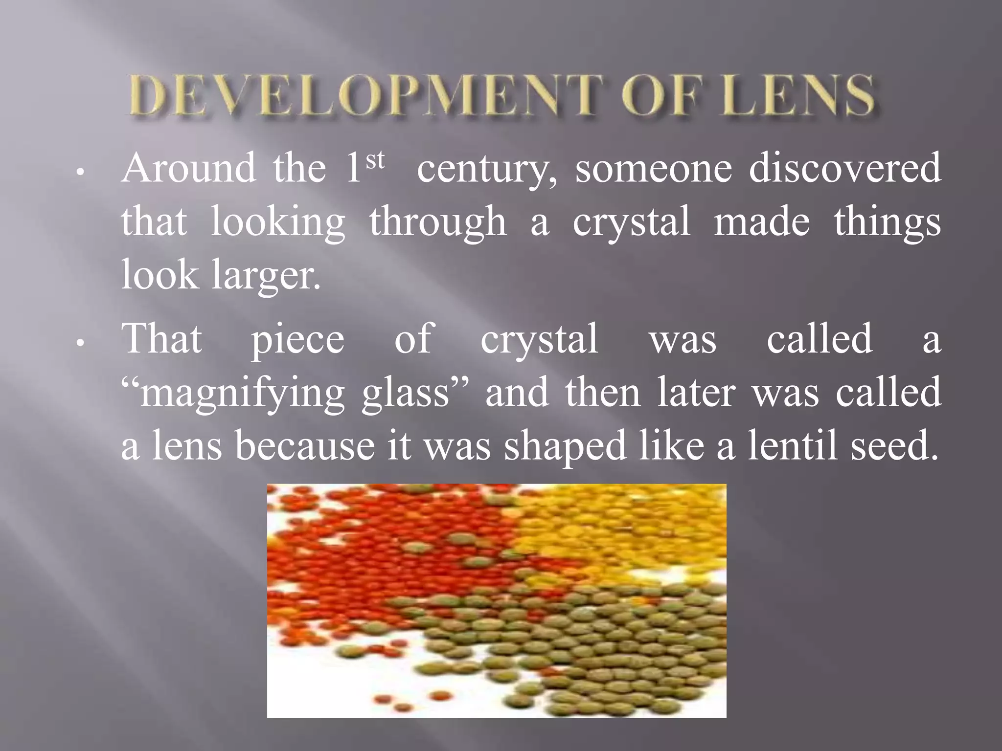
• Around the1st century, someone discovered
that looking through a crystal made things
look larger.
• That piece of crystal was called a
“magnifying glass” and then later was called
a lens because it was shaped like a lentil seed.
7.
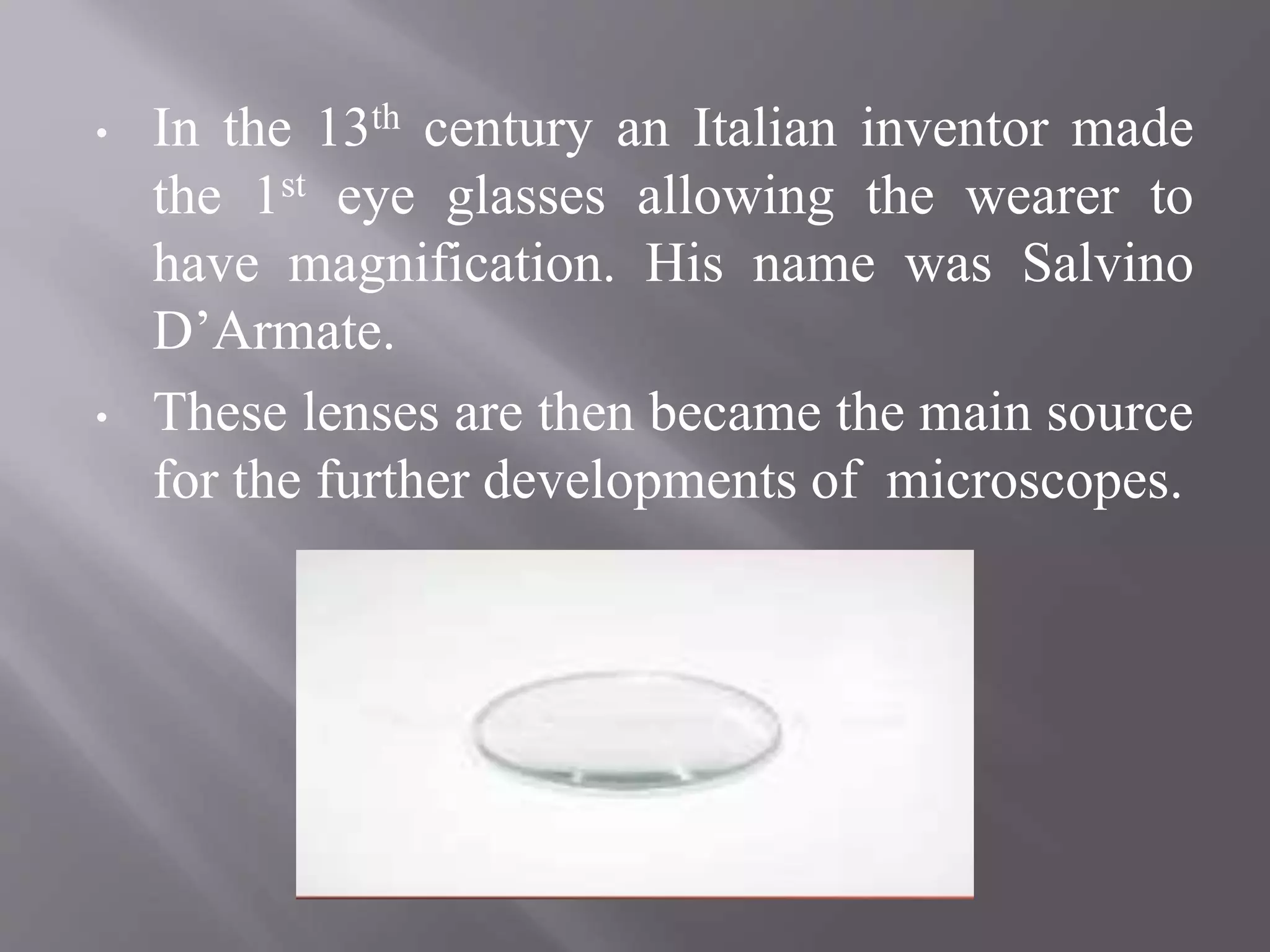
• In the13th century an Italian inventor made
the 1st eye glasses allowing the wearer to
have magnification. His name was Salvino
D’Armate.
• These lenses are then became the main source
for the further developments of microscopes.
8.
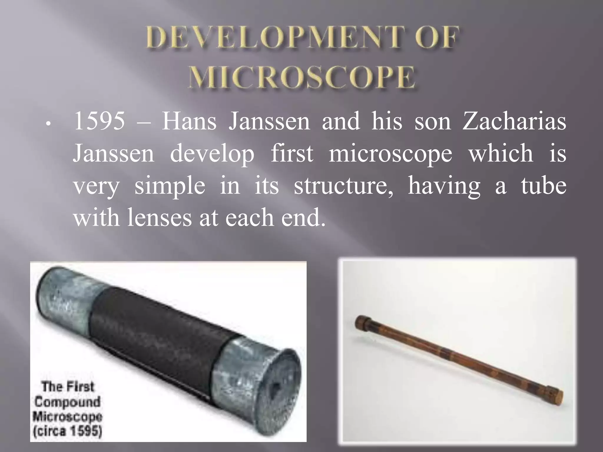
• 1595 –Hans Janssen and his son Zacharias
Janssen develop first microscope which is
very simple in its structure, having a tube
with lenses at each end.
9.
• 1609 –Galileo Galilei – compound
microscope.
• 1620 – Christian Huygens, another Dutchman
developed a simple 2- lens ocular system that
was chromatically corrected.
Later, it was perfected in the 17th century
in several countries including by Robert
Hooke (1635 - 1703) in England but most
notably by a Dutchman, Anton Van
Leeuwenhoek (1632 – 1723).
10.
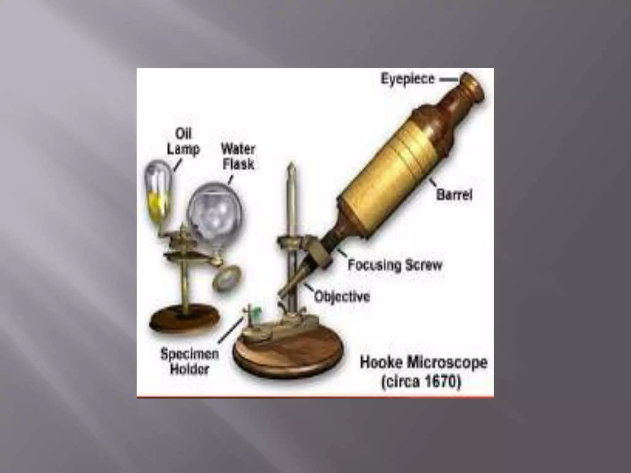
• He developeda primitive compound
microscope.
• He was the first who coined the term “Cell”.
• He produced marvelous illustrations by using
a much improved microscope with a
monocular eyepiece, a wooden tube, a stage,
and a glass globe full of water to concentrate
light onto it.
12.
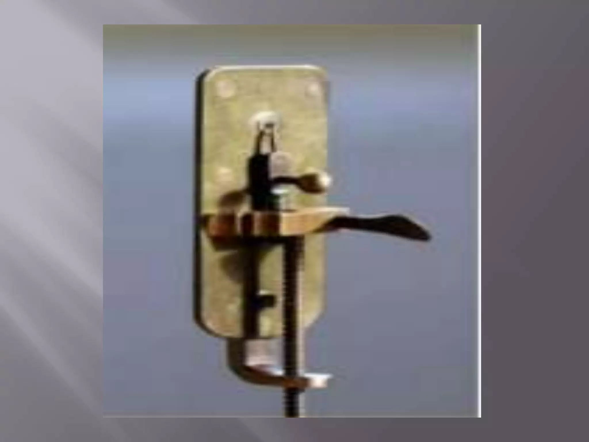
• He followedthe work of Hooke’s and the
microscope developed by him became more
popular among scientists.
• He used to grinding lenses in order to
improve the optical quality.
• The result of his work was a simple, single
convex lens, hand-held microscope.
And specimen was mounted on to the top
of pointer and viewed through hole on the
other side of microscpe.
14.
• The nextmajor invention in development of
microscope is the use of achromatic lens by
Charles Hall, in the 1730’s.
• In 1830, Joseph Lister solved the problem of
spherical aberration ( light bends at different
angles depending on where it hits the lens) by
placing at precise distances from each other.
• Combined, these two discoveries contributed
towards a marked improvement in the quality
of image.
15.
• 1932 –Frits Xernike inventor of the phase
contrast microscope.
• 1938 – Ernst Ruska, develops electron
microscope, in which use of electrons
enhanced the resolution.
• 1981 – 3 – D specimen images possible with
the invention of scanning tunneling
microscope by Gerd, Binning and Heinrich
Rohrer.
Today the number of microscopes are
develop by microscopists which greatly
contributes towards the field of microscopy.
18.
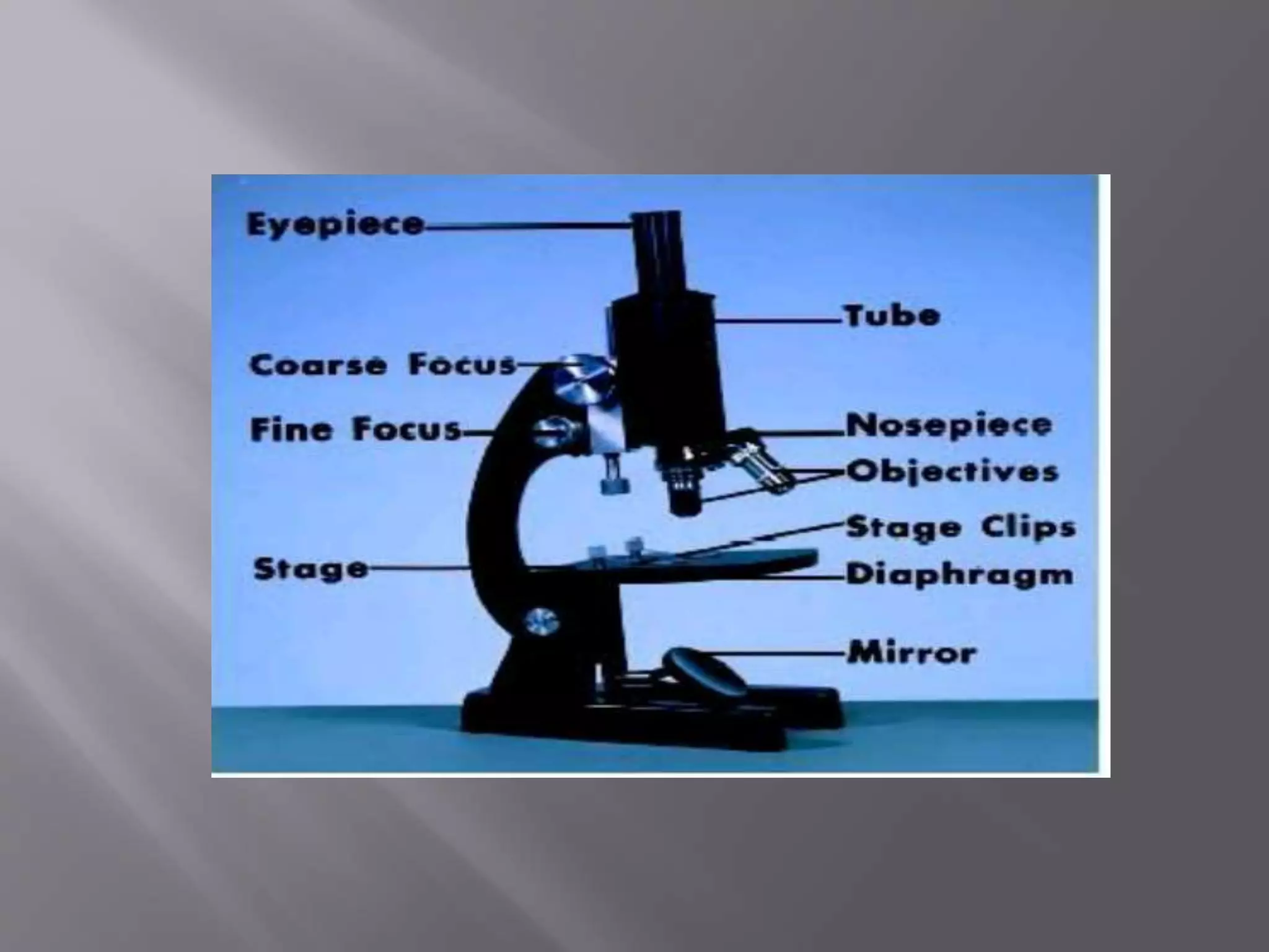
• EYE PIECELENS : The lens through which the
specimen can be seen as a magnified image. They
are usually 10x – 15x power.
• TUBE : Connect the eye piece to the objective lens.
• ARM : Supports the tube and connects it to the base.
• BASE : Horse shoe shaped structure, it bears whole
of the weight of the microscope.
• PILLAR : Small vertical projection from the base.
• STAGE : A rectangular flat plate attached to the
lower end of the arm. A hole is present in its middle
with two clamps that are meant for holding the
prepared slide in position.
19.
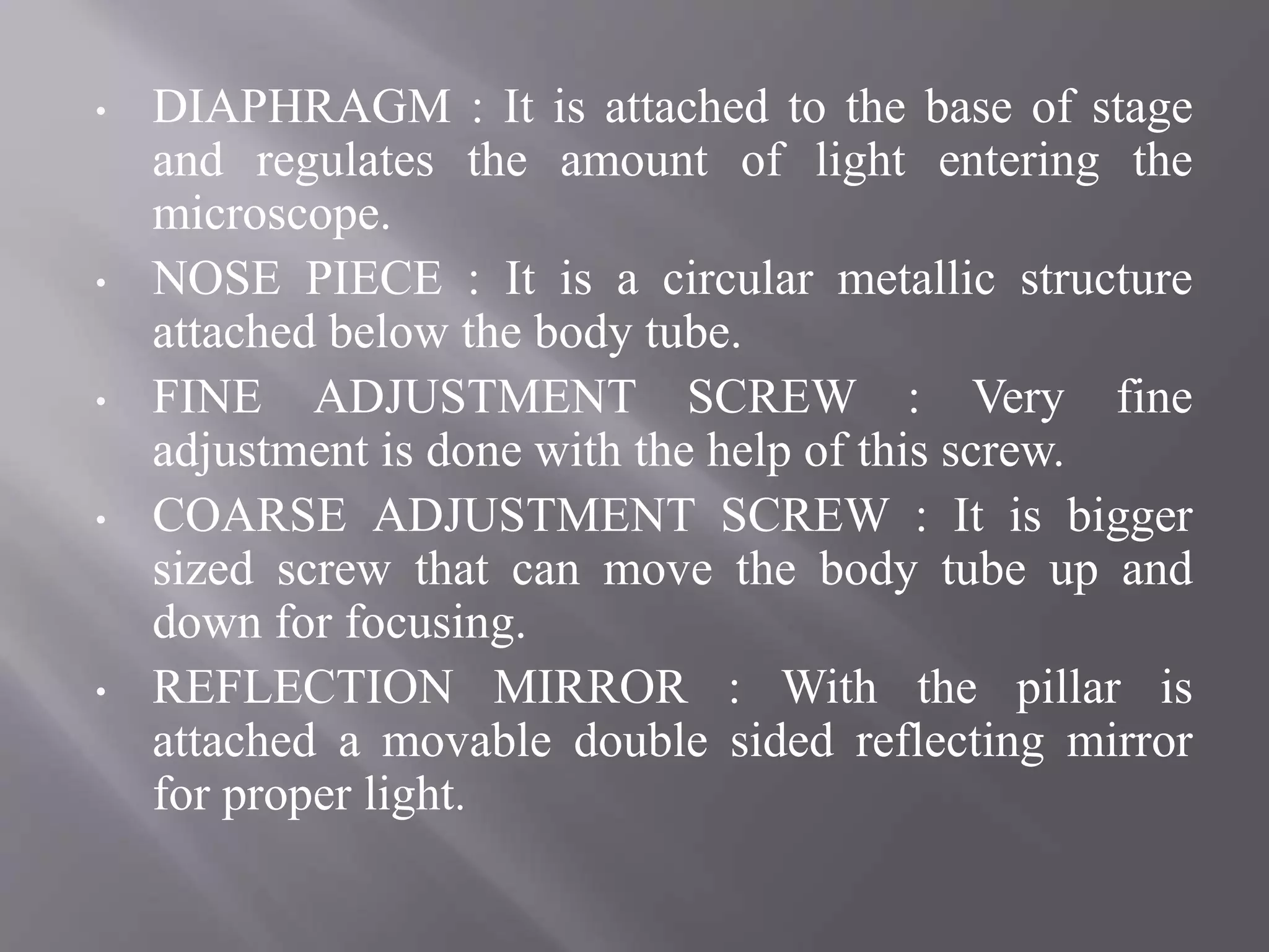
• DIAPHRAGM :It is attached to the base of stage
and regulates the amount of light entering the
microscope.
• NOSE PIECE : It is a circular metallic structure
attached below the body tube.
• FINE ADJUSTMENT SCREW : Very fine
adjustment is done with the help of this screw.
• COARSE ADJUSTMENT SCREW : It is bigger
sized screw that can move the body tube up and
down for focusing.
• REFLECTION MIRROR : With the pillar is
attached a movable double sided reflecting mirror
for proper light.
21.
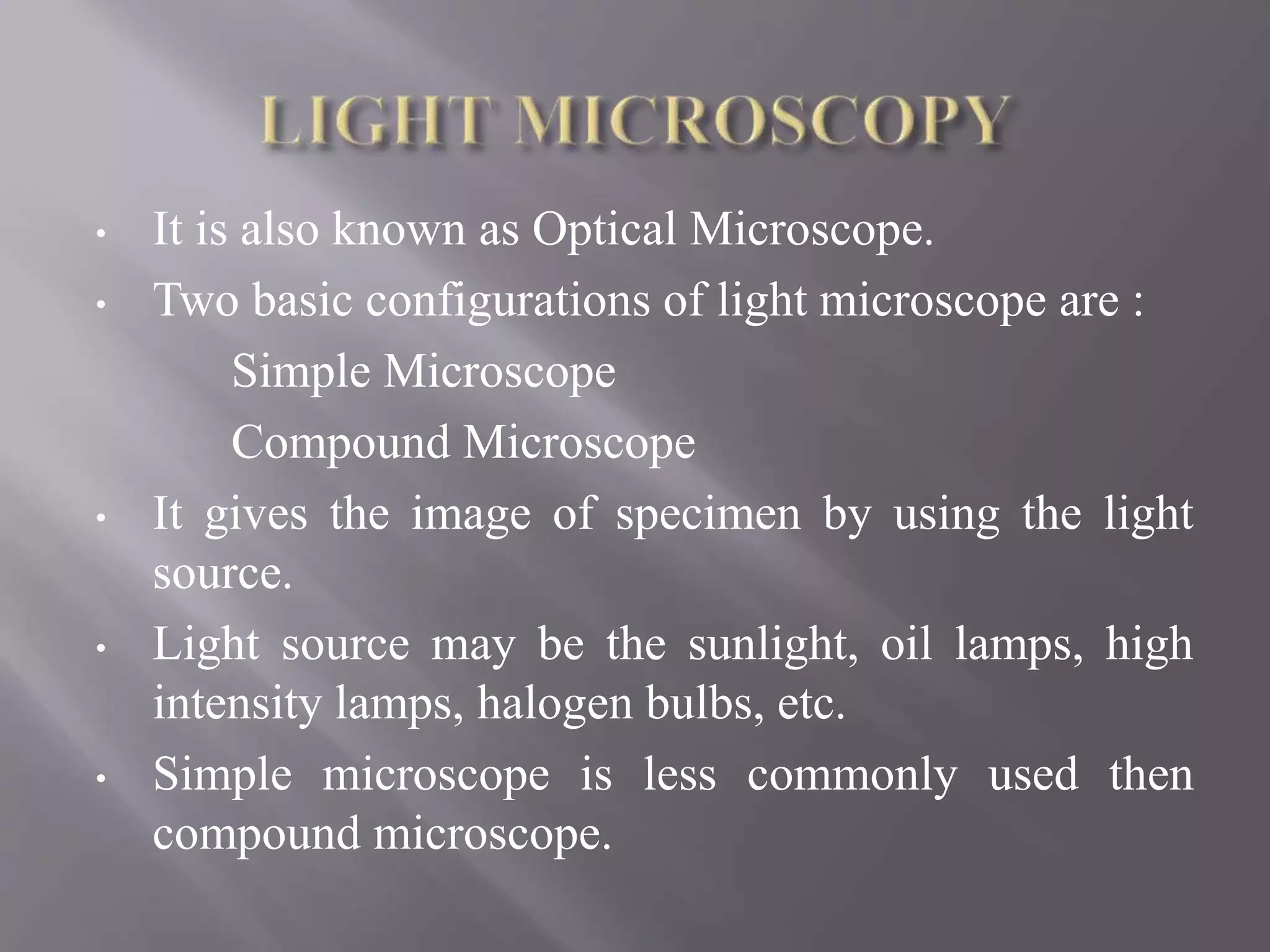
• It isalso known as Optical Microscope.
• Two basic configurations of light microscope are :
Simple Microscope
Compound Microscope
• It gives the image of specimen by using the light
source.
• Light source may be the sunlight, oil lamps, high
intensity lamps, halogen bulbs, etc.
• Simple microscope is less commonly used then
compound microscope.
22.
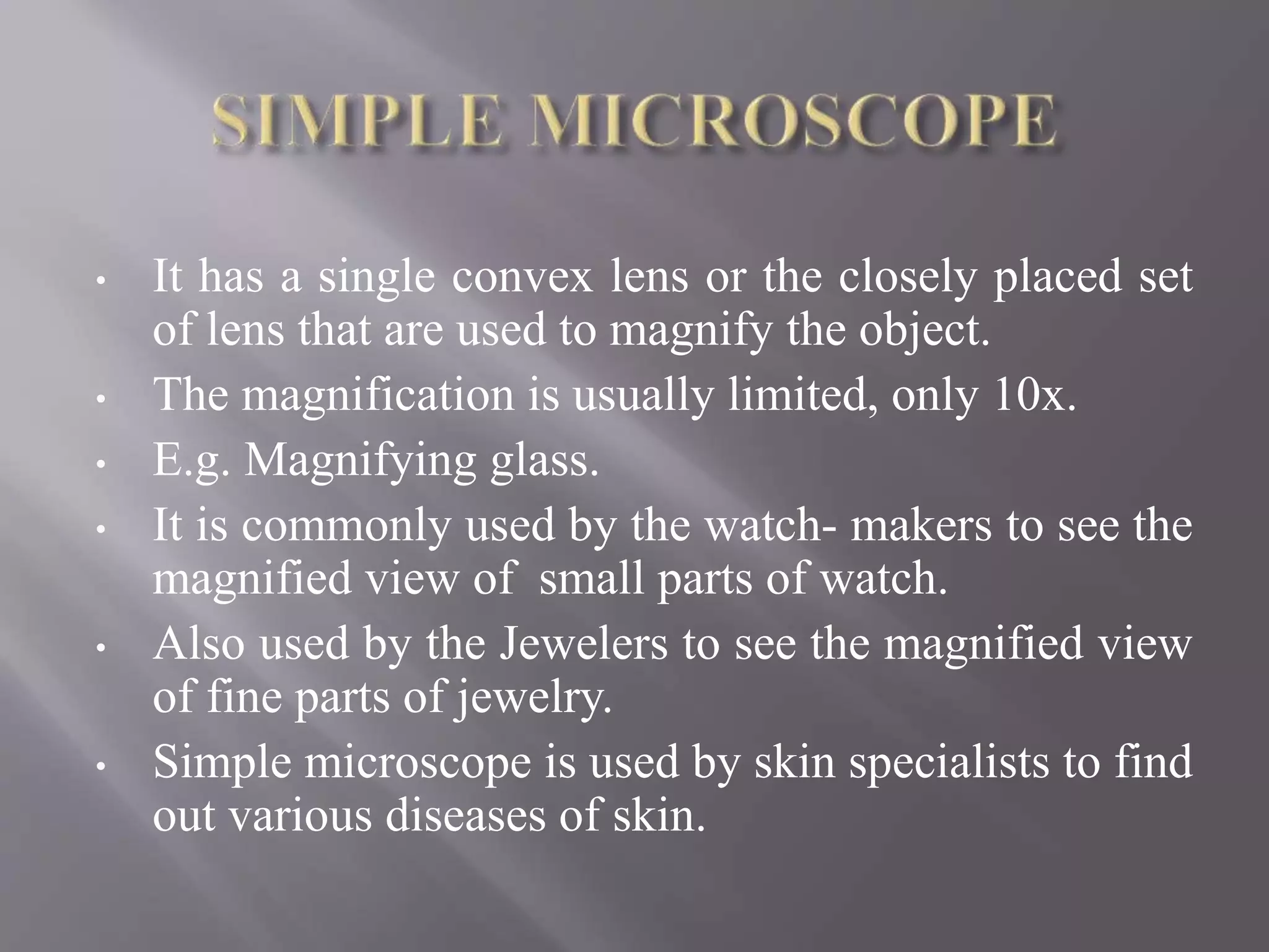
• It hasa single convex lens or the closely placed set
of lens that are used to magnify the object.
• The magnification is usually limited, only 10x.
• E.g. Magnifying glass.
• It is commonly used by the watch- makers to see the
magnified view of small parts of watch.
• Also used by the Jewelers to see the magnified view
of fine parts of jewelry.
• Simple microscope is used by skin specialists to find
out various diseases of skin.
23.
• A compoundmicroscope is an optical instrument consisting
of two convex lenses of short focal length which is used for
observing the highly magnified images of tiny objects.
• Its maximum magnifying power is 1000x.
• It mainly uses the condensers and the objectives.
• The main purpose of the condenser is to focus the light into
the plane of the object.
• Where as main task of the objective is to collect the
maximum amount of light from the object, unite it and form
a high quality magnified image of the object.
• The image thus formed can be seen through the eye lens.
• It is mainly used in the lab for viewing bacteria , fungus and
other tiny organisms.
24.
There are fivemajor types of light
microscopes named as :
• Bright Field Microscope
• Dark Field Microscope
• Fluorescence Microscope
• Phase – Contrast Microscope
• Confocal Microscope
25.
• The ordinarymicroscope is called a Bright Field
Microscope.
• It forms a dark image against a brighter background.
• Bright field microscopy is best suited to viewing
stained or naturally pigmented specimens.
• It is useless for living specimens of bacteria, or
unstained cell suspensions or tissue sections, living
photosynthetic organisms.
• Magnification power is 1000x – 2000x, greater than
2000x will give the fuzzy appearance of object.
• Algae under BFM can be seen as :
27.
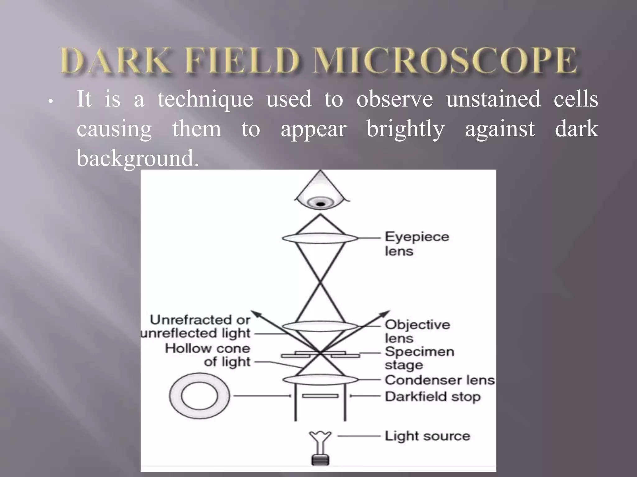
• It isa technique used to observe unstained cells
causing them to appear brightly against dark
background.
28.
• Dark fieldmicroscope has a specialized condenser with a dark
field stop that obstructs the path of light from light source
centrally, but allowing a peripheral ring of light.
• Thus the condenser produces a hollow cone of light .
• This cone of light converges on the object and diverge from
there as an inverted hollow cone.
• No light enter into the objective, as it remains in the dark cone
and the field appear dark give rise to the brighter image.
• Volvox under DFM :
29.
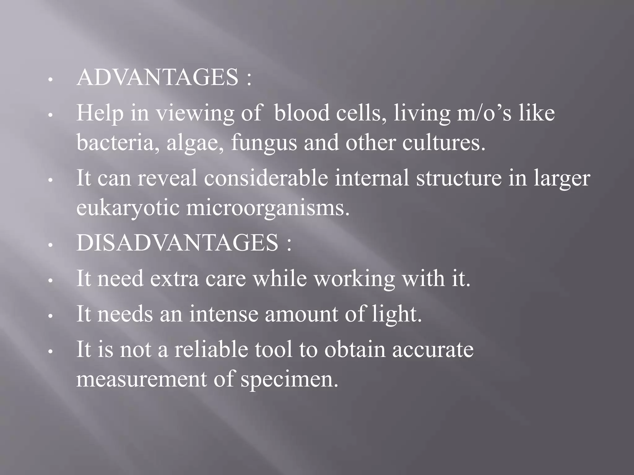
• ADVANTAGES :
•Help in viewing of blood cells, living m/o’s like
bacteria, algae, fungus and other cultures.
• It can reveal considerable internal structure in larger
eukaryotic microorganisms.
• DISADVANTAGES :
• It need extra care while working with it.
• It needs an intense amount of light.
• It is not a reliable tool to obtain accurate
measurement of specimen.
30.
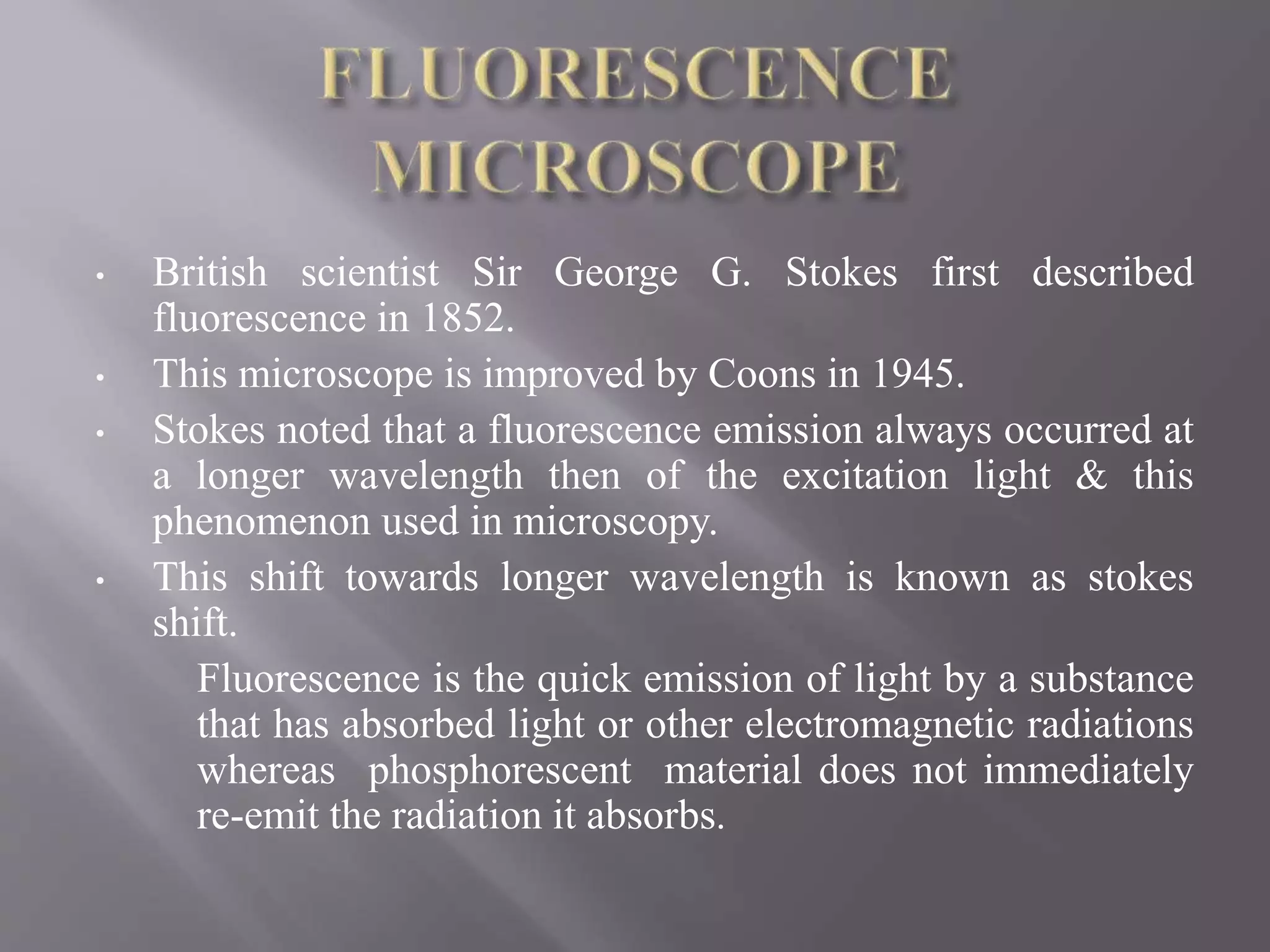
• British scientistSir George G. Stokes first described
fluorescence in 1852.
• This microscope is improved by Coons in 1945.
• Stokes noted that a fluorescence emission always occurred at
a longer wavelength then of the excitation light & this
phenomenon used in microscopy.
• This shift towards longer wavelength is known as stokes
shift.
Fluorescence is the quick emission of light by a substance
that has absorbed light or other electromagnetic radiations
whereas phosphorescent material does not immediately
re-emit the radiation it absorbs.
31.
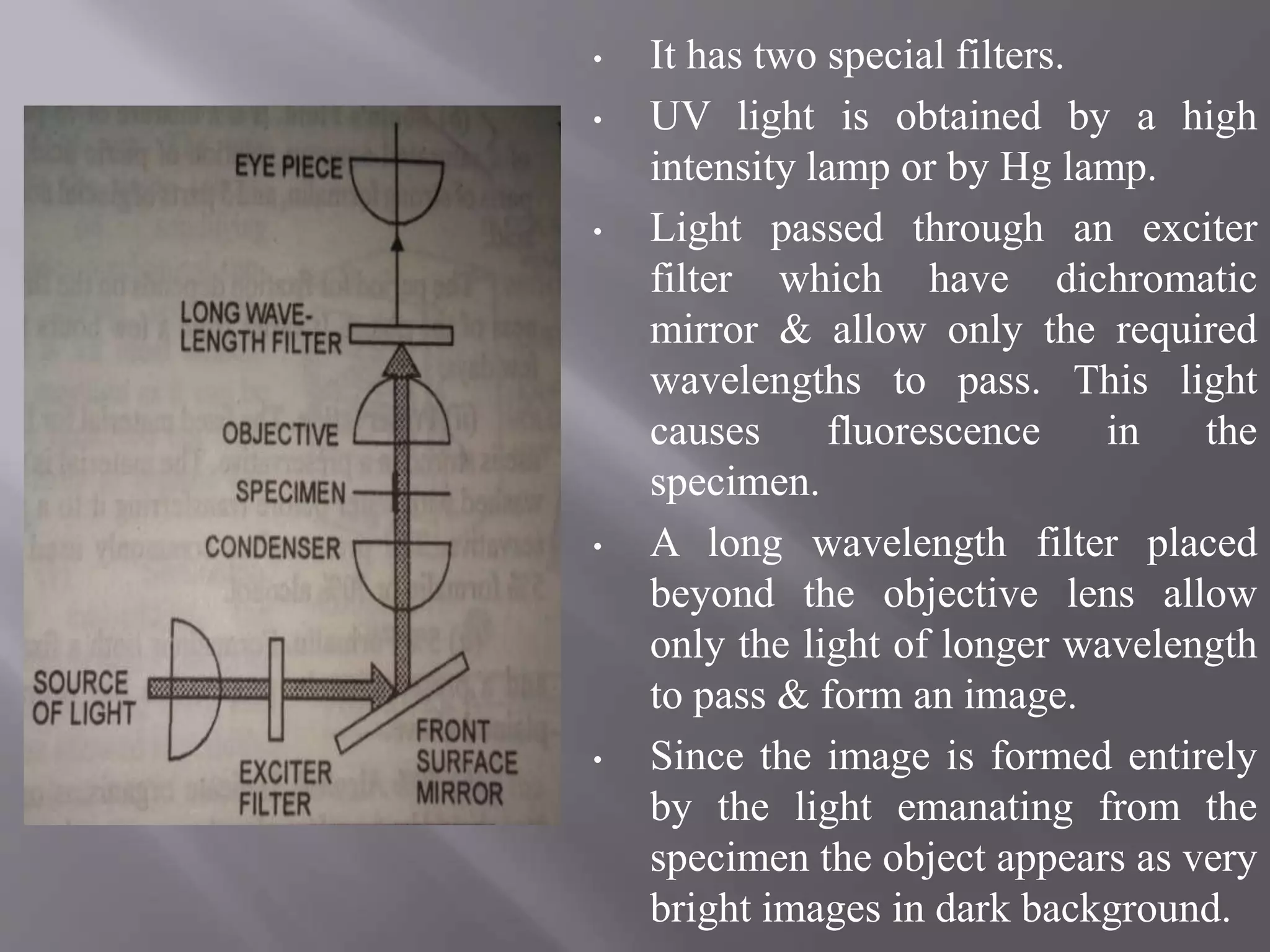
• It hastwo special filters.
• UV light is obtained by a high
intensity lamp or by Hg lamp.
• Light passed through an exciter
filter which have dichromatic
mirror & allow only the required
wavelengths to pass. This light
causes fluorescence in the
specimen.
• A long wavelength filter placed
beyond the objective lens allow
only the light of longer wavelength
to pass & form an image.
• Since the image is formed entirely
by the light emanating from the
specimen the object appears as very
bright images in dark background.
33.
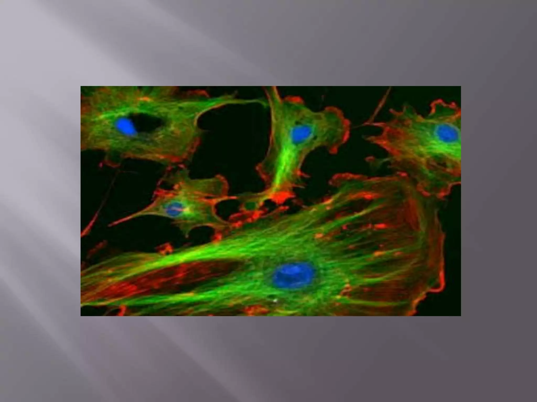
• The previousimage is the image of endothelial
cells having bluish nuclei and green
microtubules.
• The fluorescent compounds which occurs in
tissues and cells include collagen, chlorophyll,
riboflavin & vitamin A.
• It is also possible to make certain compounds
fluorescent by treatment with fluorescent dyes,
the fluorochromes, that are introduced into the
cells.
• This method has been used in the study of
chromosome behavior.
34.
• ADVANTAGES :
•To locate fluorescent compounds in cells and
tissues.
• To identify strains of bacteria in infected tissues by
staining them with fluorochromes.
• The internal structure can be determined through it.
• DISADVANTAGES :
• High cost.
• UV rays may effect the person who work with this
microscope.
35.
• It wasthe 1st microscopic method which
allow the observation of living cells.
• It was invented by Frits Zernike and was
awarded noble prize in 1953.
• It uses visible light as the source of
illumination.
• Phase contrast objective lens comes in 4x,
10x, 20x and 40x power.
• Total magnification power is 40x to 400x.
36.
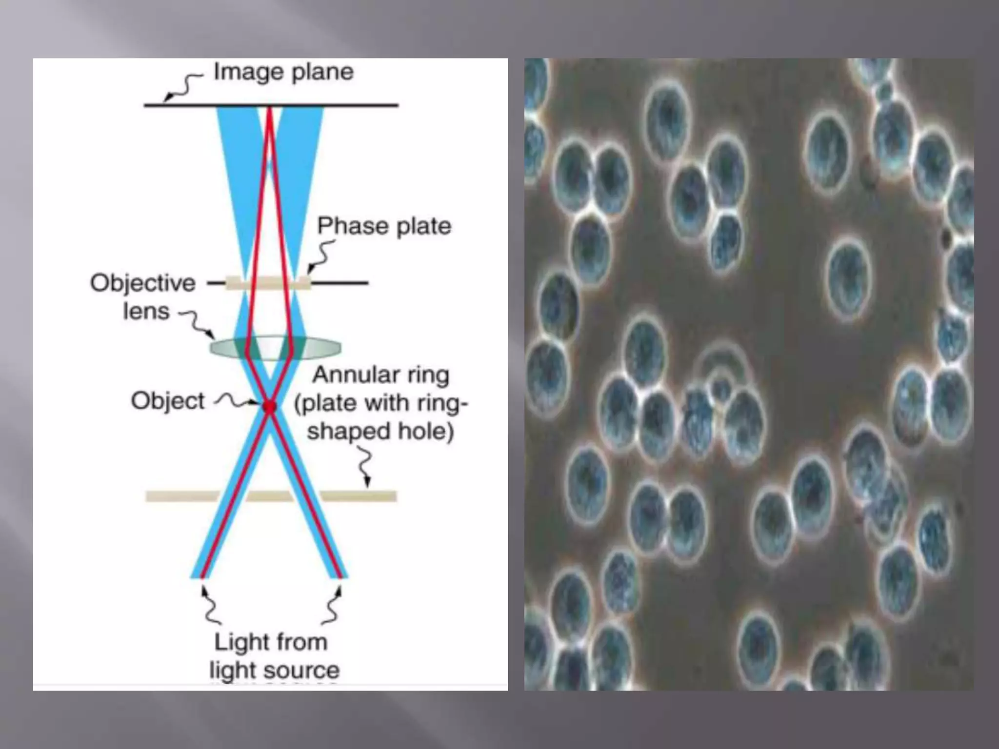
• It usesa conventional light microscope fitted
with a phase – contrast objective and phase -
contrast condenser.
• Light passing through one material into another
material of slightly different refractive index or
thickness will undergo a change in phase.
• This changes are translated into variations in
brightness of the structures.
• By this microscope it is possible to reveal
differences in cell and their structures that are
not described by other microscopes.
• Image under PCM showing the cast in urine :
38.
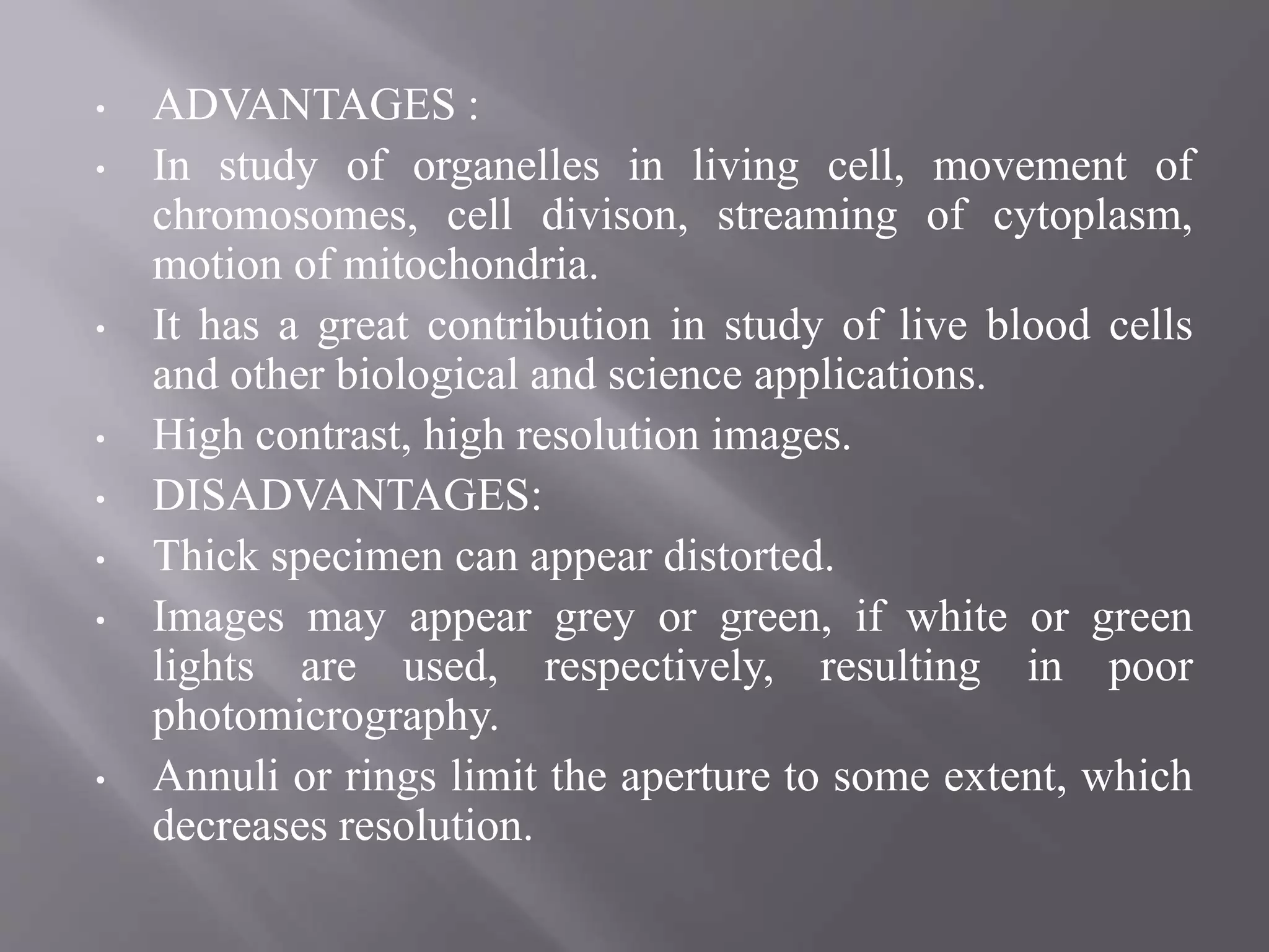
• ADVANTAGES :
•In study of organelles in living cell, movement of
chromosomes, cell divison, streaming of cytoplasm,
motion of mitochondria.
• It has a great contribution in study of live blood cells
and other biological and science applications.
• High contrast, high resolution images.
• DISADVANTAGES:
• Thick specimen can appear distorted.
• Images may appear grey or green, if white or green
lights are used, respectively, resulting in poor
photomicrography.
• Annuli or rings limit the aperture to some extent, which
decreases resolution.
39.
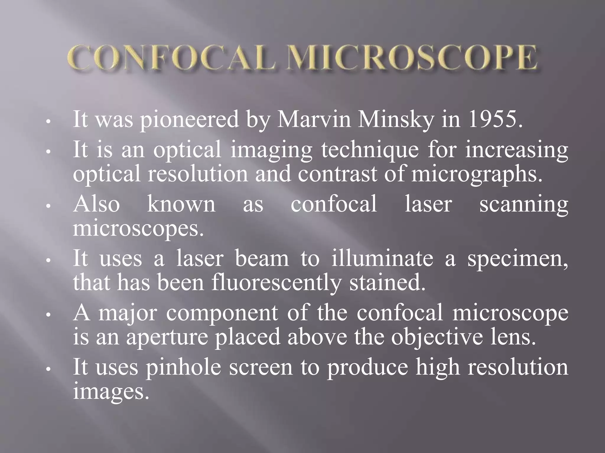
• It waspioneered by Marvin Minsky in 1955.
• It is an optical imaging technique for increasing
optical resolution and contrast of micrographs.
• Also known as confocal laser scanning
microscopes.
• It uses a laser beam to illuminate a specimen,
that has been fluorescently stained.
• A major component of the confocal microscope
is an aperture placed above the objective lens.
• It uses pinhole screen to produce high resolution
images.
41.
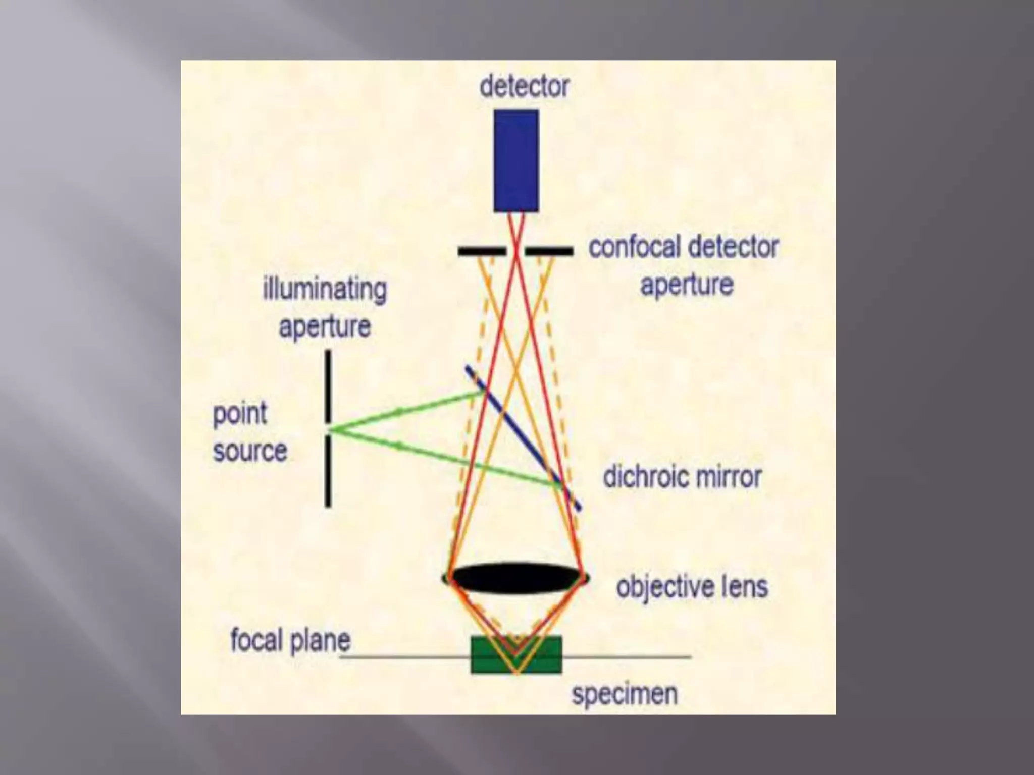
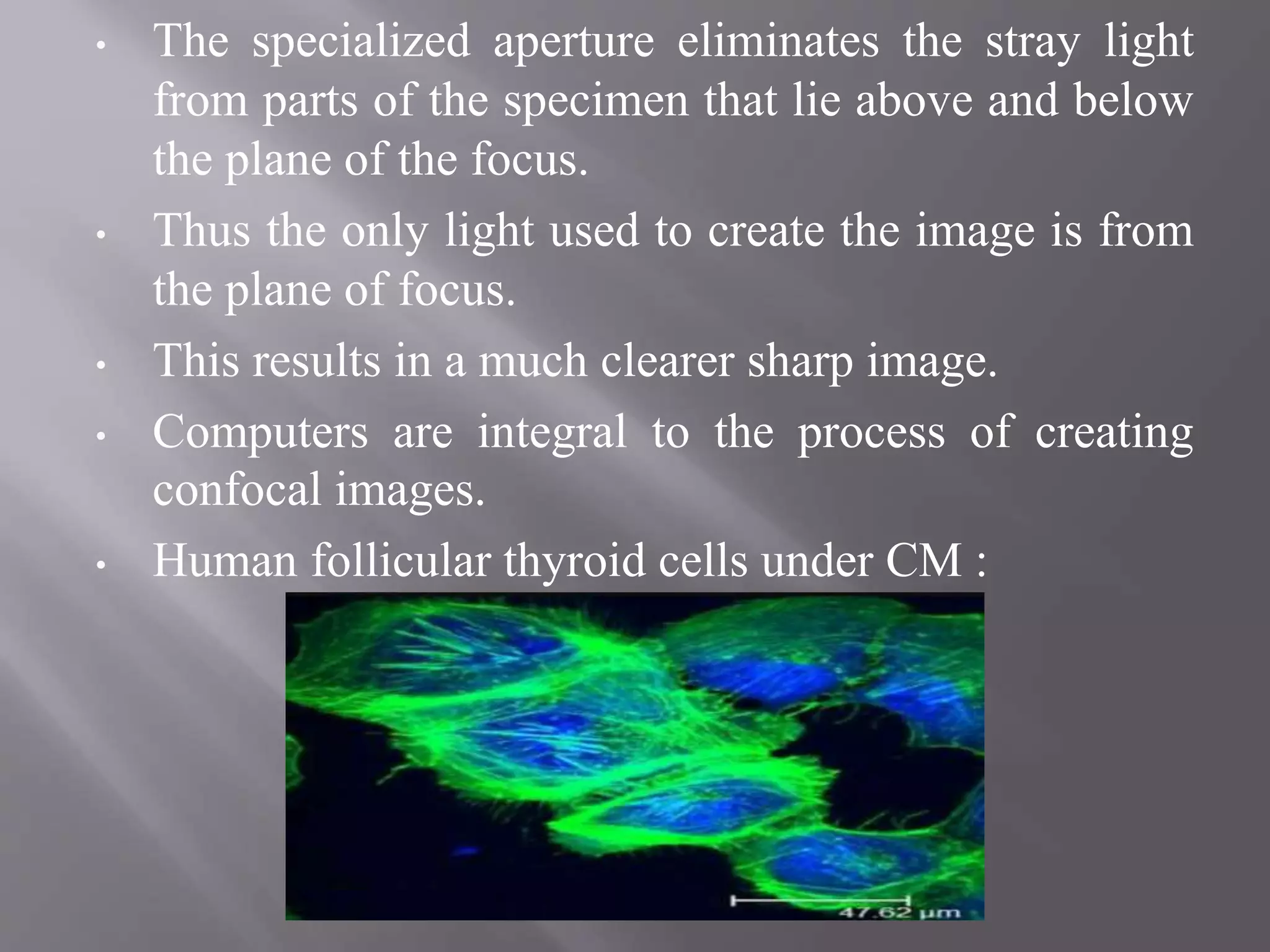
• The specializedaperture eliminates the stray light
from parts of the specimen that lie above and below
the plane of the focus.
• Thus the only light used to create the image is from
the plane of focus.
• This results in a much clearer sharp image.
• Computers are integral to the process of creating
confocal images.
• Human follicular thyroid cells under CM :
42.
• ADVANTAGES :
•Multi – fluorescent specimen with distinguishable 3-
dimensionally image.
• Have great contribution in the study of biofilms.
• It gives the sharp image without the processing of
tissue.
• Serial optical section can be controlled.
• DISADVANTAGES :
• The technique requires more training and experience
to be successful.
• High cost.
• Excitation wavelengths become more expensive
under ultraviolet region.
43.
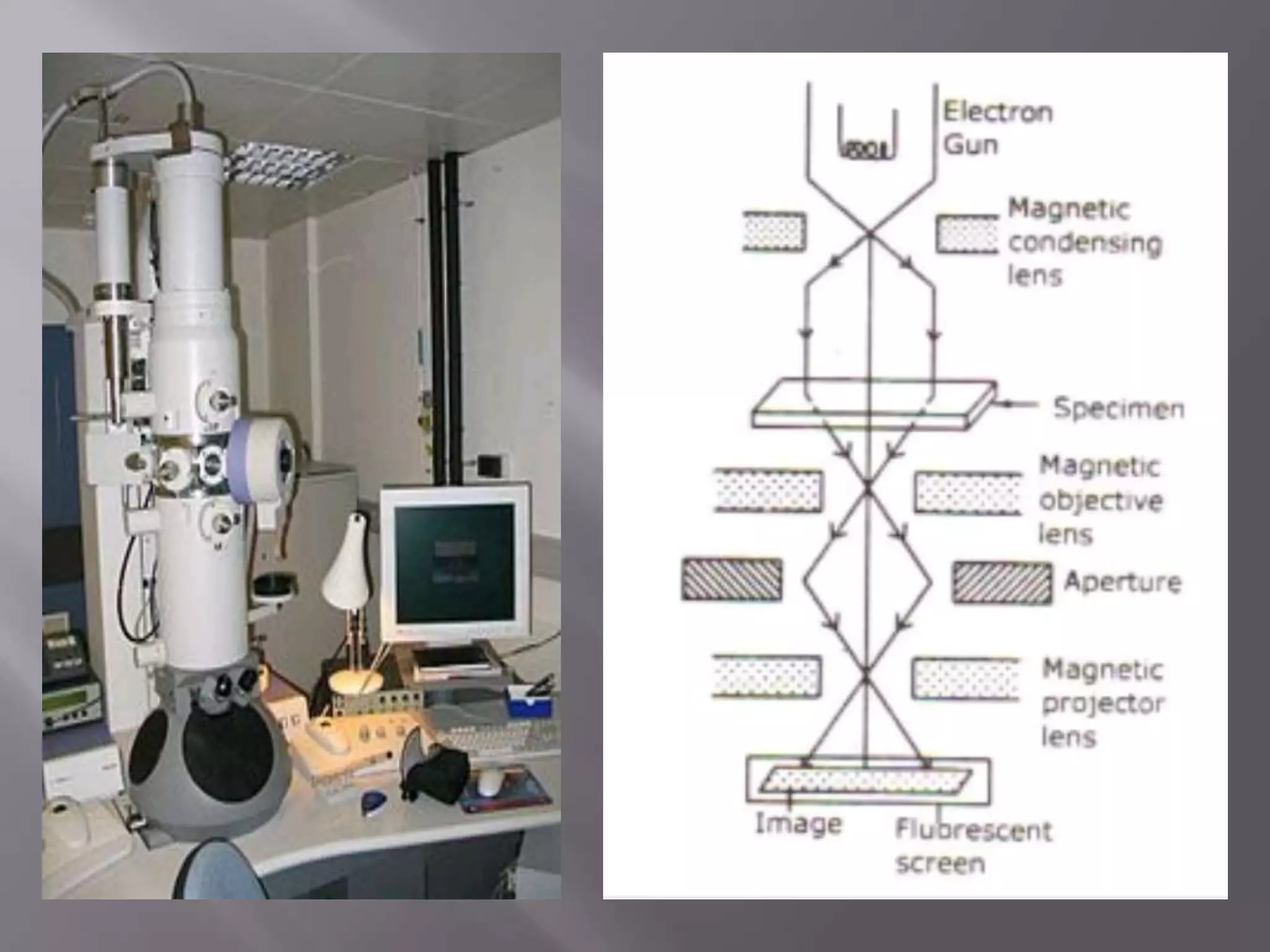
• It wasinvented by Knoll and Ruska in 1931.
• It has electromagnetic lenses which are coils
of wires (electromagnets).
• Its essential parts are :
• Metal (Tungsten) Filament : Source of beam
of electrons for illumination.
• Electromagnetic Condenser Lens : Collects
and focuses the beam of electrons on the
object.
• Electromagnetic Objective Lens : Produces
an enlarged image of the object.
44.
• Electromagnetic ProjectorLens : It further
magnifies the image and projects it onto a
fluorescent viewing or photographic plate.
• The photographs produced by EM are called
electron micrographs.
• Image results from the differential scattering
of electrons from the cell components.
• Denser the material, greater is the scattering
of electrons irrespective of chemical
composition.
45.
• There aretwo main types of electron
microscopy are :
Transmission Electron Microscope (TEM)
Scanning Electron Microscope (SEM)
• These two types used the electrons and a
stained sample to give a highly magnified and
a high resolution image.
• But working of each microscope is very
different from another.
46.
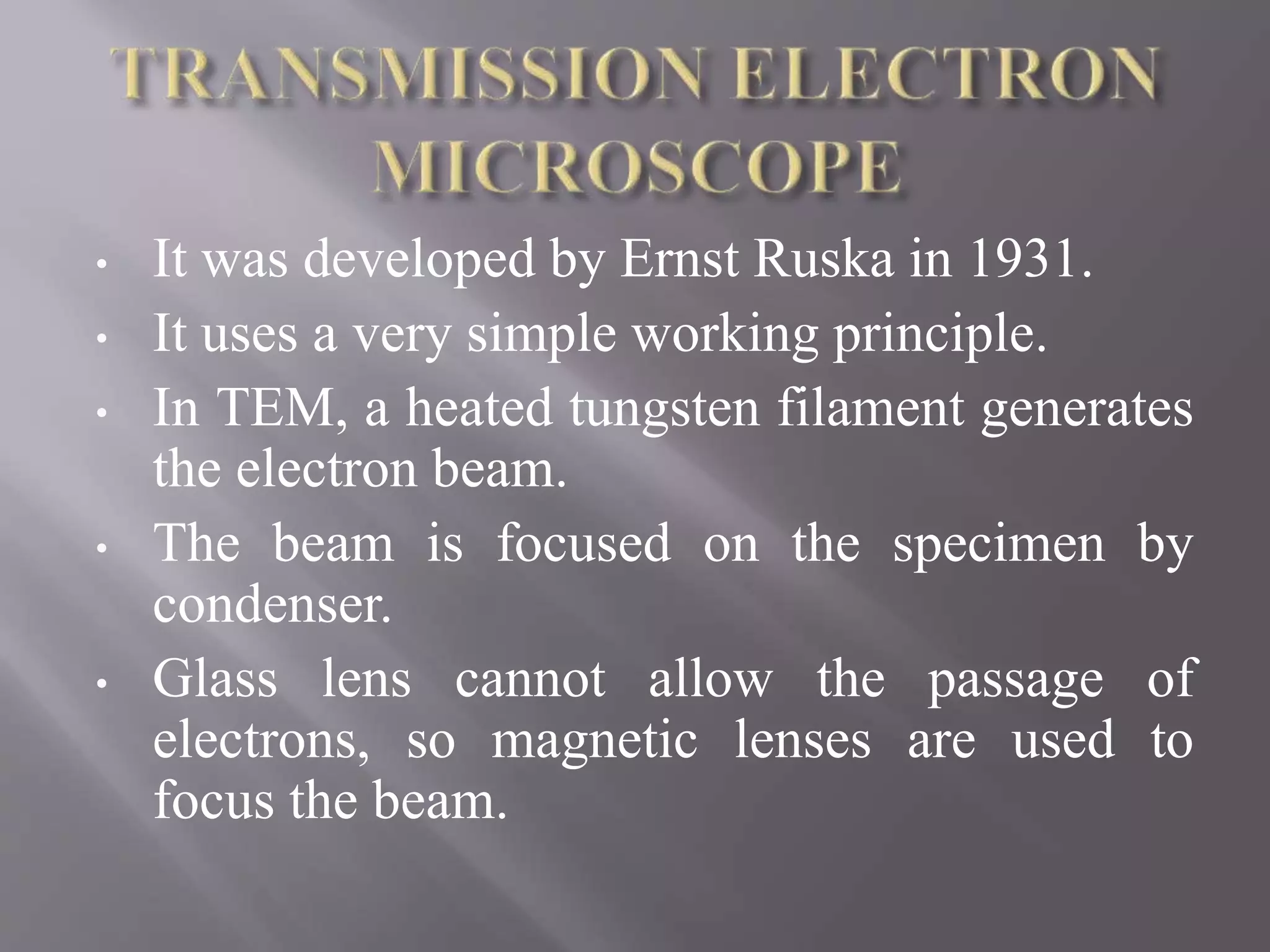
• It wasdeveloped by Ernst Ruska in 1931.
• It uses a very simple working principle.
• In TEM, a heated tungsten filament generates
the electron beam.
• The beam is focused on the specimen by
condenser.
• Glass lens cannot allow the passage of
electrons, so magnetic lenses are used to
focus the beam.
48.
• The columnconsisting the lenses and specimen
must be under high vacuum to obtain a clear image.
• Because electrons are deflected by collisions with
air molecules.
• The specimen scatters some electrons but those that
passed through, are used to form an enlarged image.
• Image is then formed on a fluorescent screen.
• A denser region in the specimen will scatters more
electrons since it appears darker on the image.
• These regions are said to be electron dense.
• In-contrast, electron–transparent regions are
brighter.
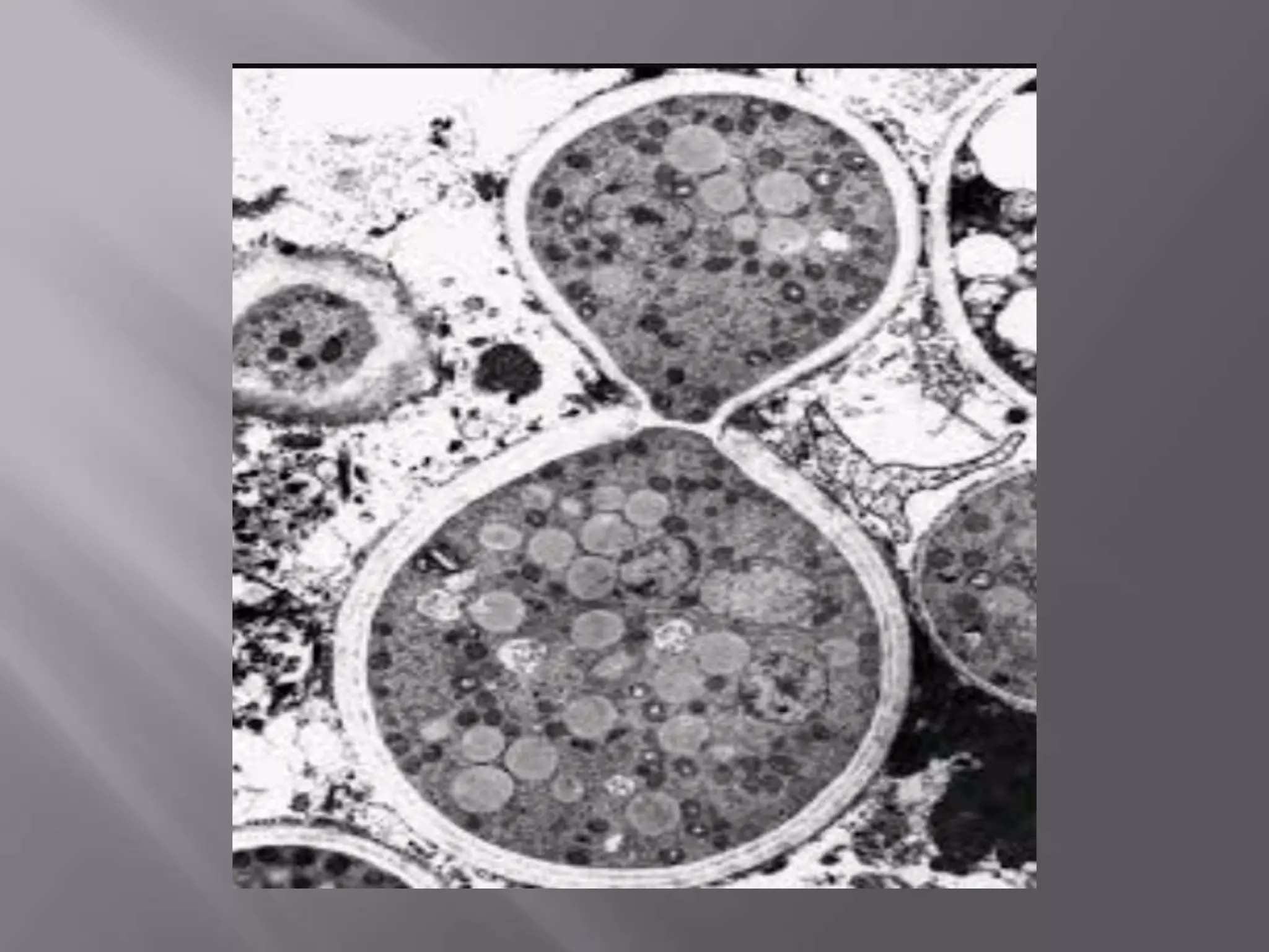
• The image can be recorded on a photographic film.
• Yeast like cells can be seen as :
50.
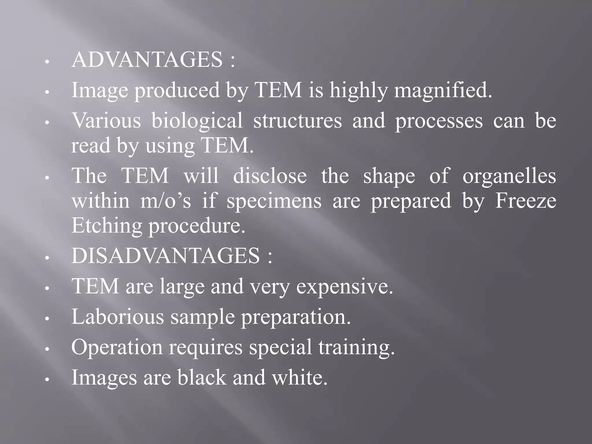
• ADVANTAGES :
•Image produced by TEM is highly magnified.
• Various biological structures and processes can be
read by using TEM.
• The TEM will disclose the shape of organelles
within m/o’s if specimens are prepared by Freeze
Etching procedure.
• DISADVANTAGES :
• TEM are large and very expensive.
• Laborious sample preparation.
• Operation requires special training.
• Images are black and white.
51.
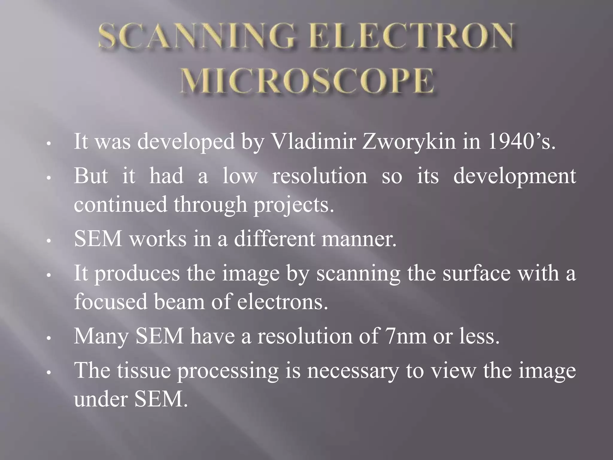
• It wasdeveloped by Vladimir Zworykin in 1940’s.
• But it had a low resolution so its development
continued through projects.
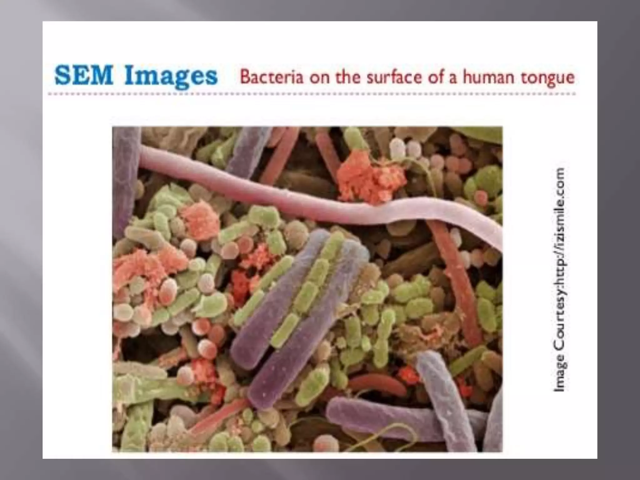
• SEM works in a different manner.
• It produces the image by scanning the surface with a
focused beam of electrons.
• Many SEM have a resolution of 7nm or less.
• The tissue processing is necessary to view the image
under SEM.
53.
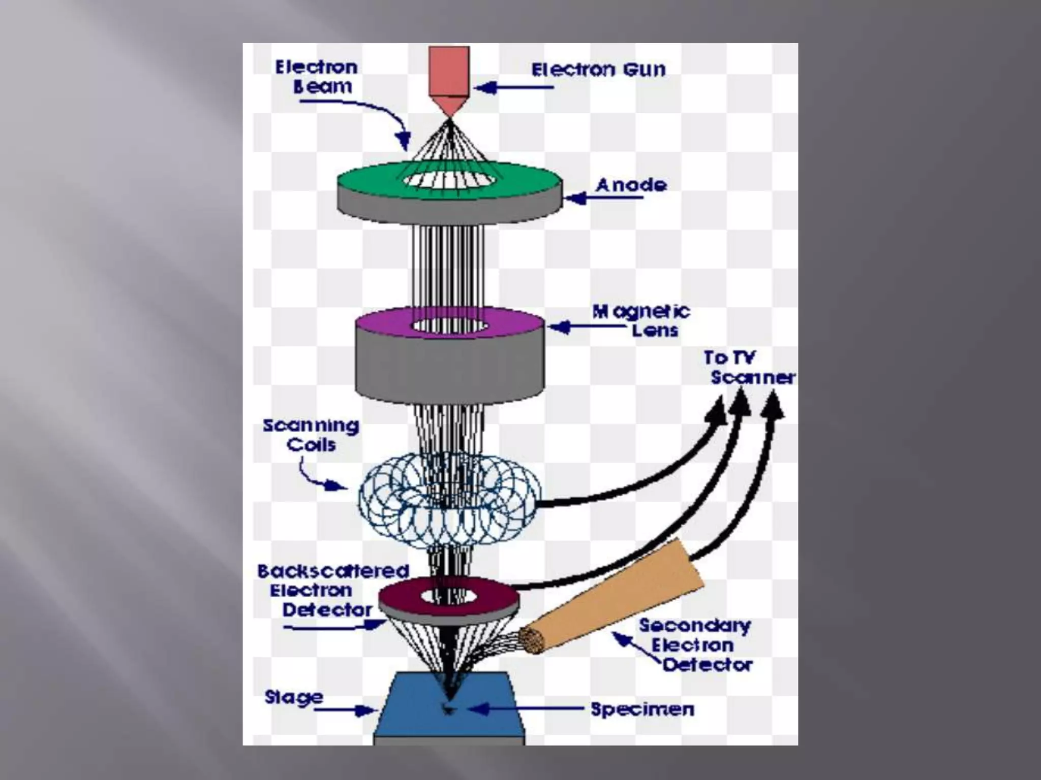
• To createan image, the SEM creates a narrow,
tapered electron beam back and forth over the
specimen.
• When the beam strikes a particular area, surface
atoms discharge a tiny shower of electrons called
secondary electrons.
• These electrons are trapped by a special detector.
• When these electrons enters the detector strikes a
scintillator causing it to emit light flashes.
• Due to this a photomultiplier converts to an
electrical current and amplifies.
• The signal is sent to a cathode ray tube and
• Produces an image like a television picture, which
can be viewed or photographed.
55.
• ADVANTAGES :
•It gives the detailed 3D image & versatile
information of the specimen.
• The instrument works very fast.
• Used in the examination of surfaces of m/o’s
and also the human skin and lining of the gut.
• Data can be generated digitally.
• DISADVANTAGES :
• Very expensive and large.
• Requires experience to operate.
• Limited to solid samples.
56.
• Dr. GerdBinning and Dr. Heinrich Rohrer invented
the 1st scanning tunneling microscope in 1981.
• This was a significance breakthrough in the field of
nanotechnology.
• Because it allowed scientists to view a
representation of the surface of samples to an atomic
level.
• Thus, it involves a physical probe that scans over
the surface of a specimen gathering data i.e. used to
generate the image & manipulate the atoms.
57.
• There aretwo main types of SPM
that are named as
• Scanning Tunneling Microscope
• Atomic Force Microscope
• They may have a magnification of
about 100 millions.
58.
• It hasa needle like probe with a very sharp point that
there is only one atom at its tip.
• This probe is lowered toward the specimen surface
until its electron cloud just touches that of the surface
atoms.
• If a small voltage is applied b/w the tip and specimen
electrons flow through a narrow channel in the
electron cloud.
• The arrangement of atoms on the specimen surface
determined by moving the tip back & forth over the
surface.
59.
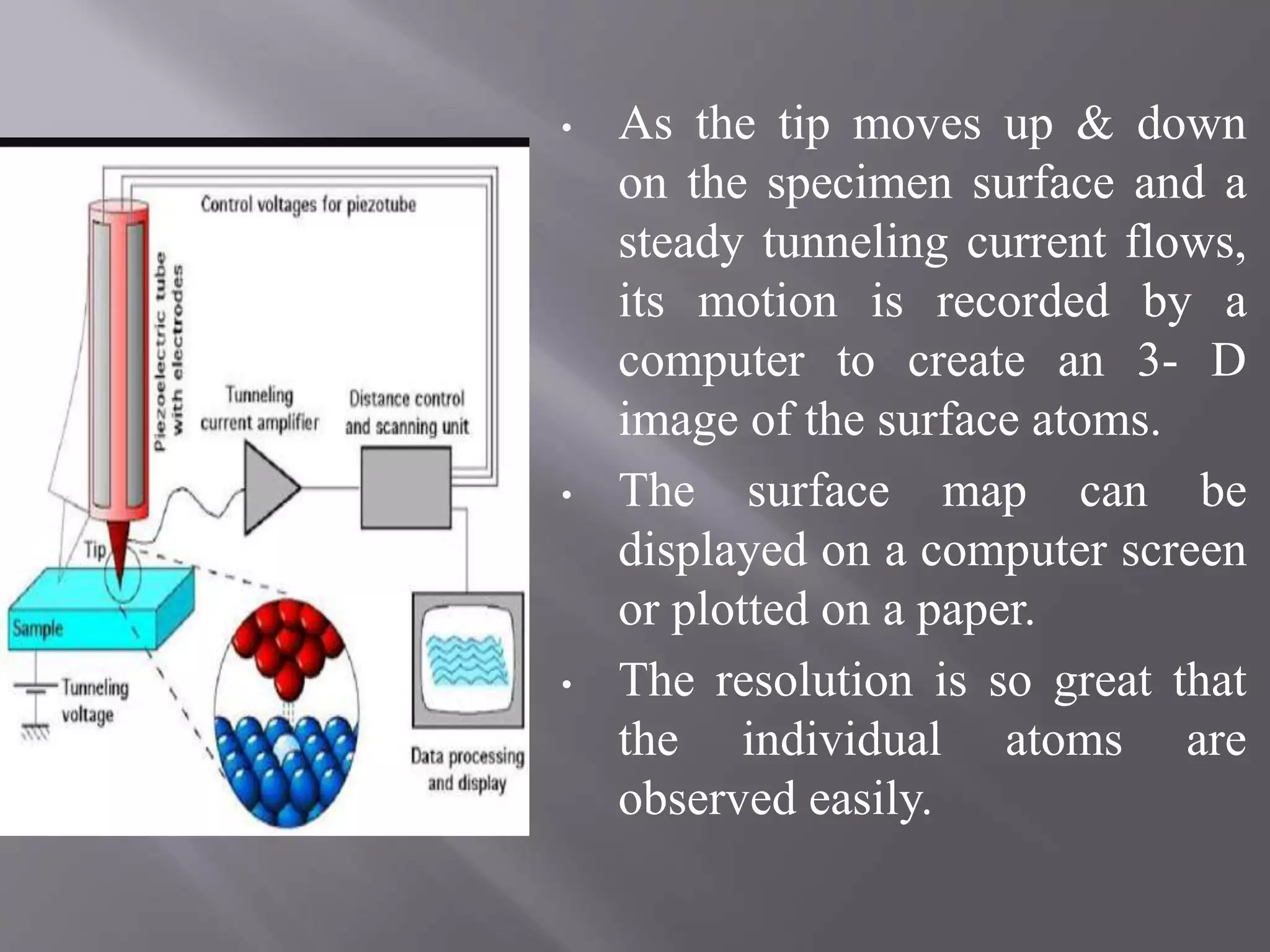
• As thetip moves up & down
on the specimen surface and a
steady tunneling current flows,
its motion is recorded by a
computer to create an 3- D
image of the surface atoms.
• The surface map can be
displayed on a computer screen
or plotted on a paper.
• The resolution is so great that
the individual atoms are
observed easily.
60.
• Binning, Quateand Gerber invented the AFM in
1985.
• It moves a sharp probe over the specimen surface
while keeping the distance b/w the probe tip & the
surface constant.
• It does so by exerting a small force on tip that will
not cause damage to surface.
• the tip used to probe the specimen is attached to the
cantilever.
• As the probe passes over the specimen’s surface the
cantilever is deflected vertically.
61.
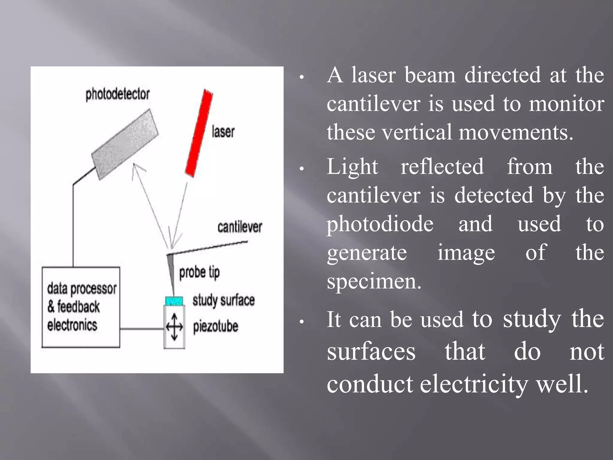
• A laserbeam directed at the
cantilever is used to monitor
these vertical movements.
• Light reflected from the
cantilever is detected by the
photodiode and used to
generate image of the
specimen.
• It can be used to study the
surfaces that do not
conduct electricity well.
62.
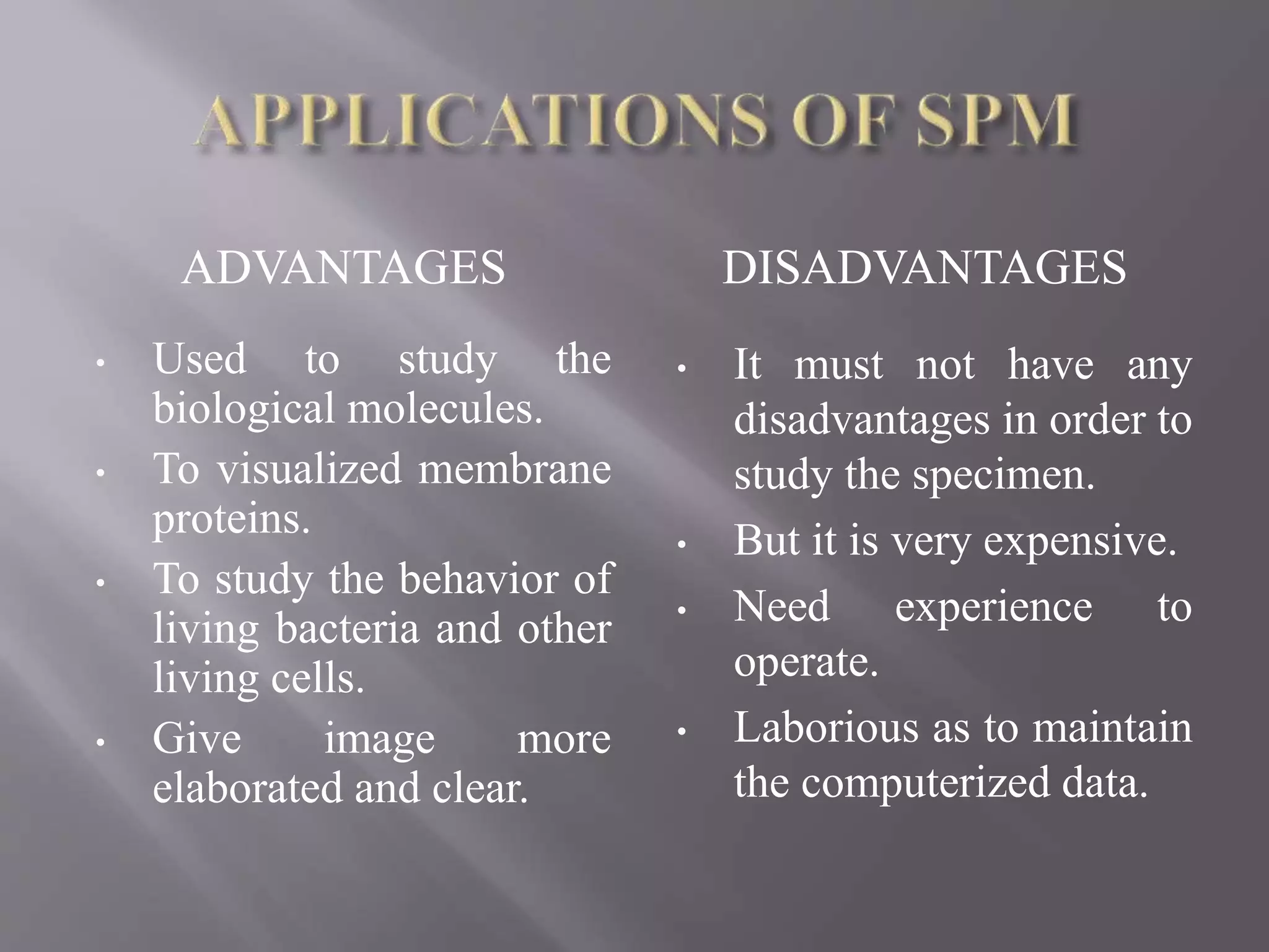
ADVANTAGES DISADVANTAGES
• Usedto study the
biological molecules.
• To visualized membrane
proteins.
• To study the behavior of
living bacteria and other
living cells.
• Give image more
elaborated and clear.
• It must not have any
disadvantages in order to
study the specimen.
• But it is very expensive.
• Need experience to
operate.
• Laborious as to maintain
the computerized data.