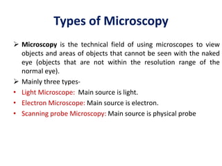
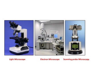
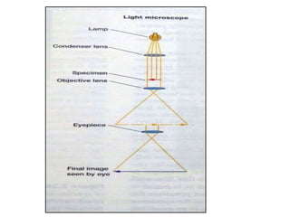
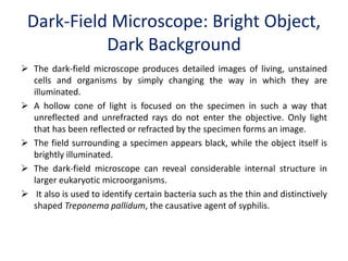
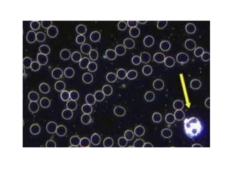
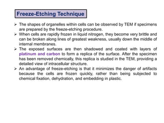
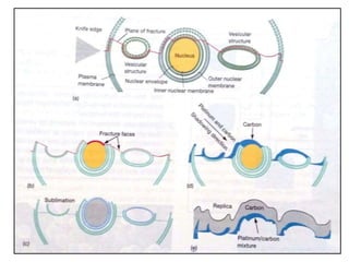
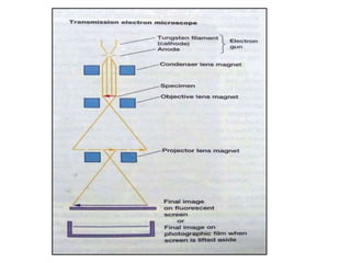
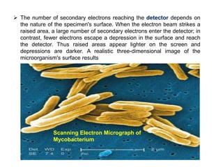
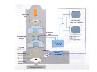
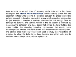
Microscopy is the technical field of using microscopes to view objects that cannot be seen with the naked eye. There are three main types of microscopy - light microscopy, which uses visible light; electron microscopy, which uses electrons; and scanning probe microscopy, which uses a physical probe. Light microscopes like brightfield, darkfield, phase contrast, and fluorescence microscopes are commonly used to view living and stained specimens. Electron microscopes have much higher resolving power than light microscopes and are able to view much smaller structures. Transmission electron microscopes form images using electrons transmitted through thin specimens while scanning electron microscopes form images from electrons emitted from surfaces.