Downloaded 156 times


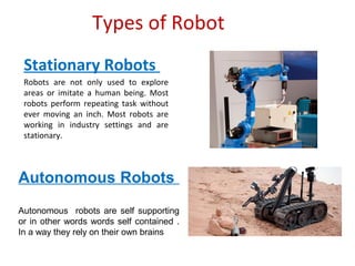
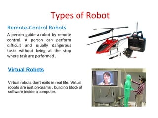


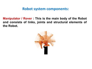


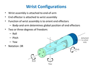

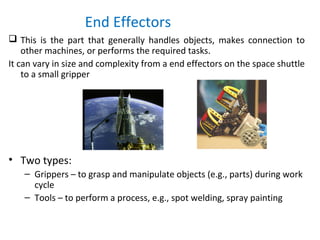
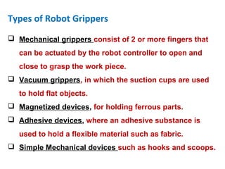


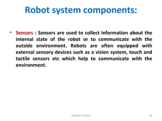
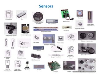
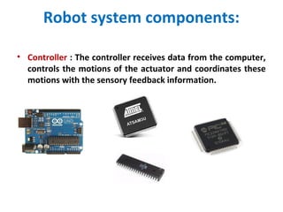


This document provides information about robots and their classification and components. It discusses the different types of robots according to their mobility and autonomy as well as the typical components that make up a robot system, including manipulators, end effectors, actuators, sensors, and controllers. It also describes various robot configurations and their corresponding work envelopes.