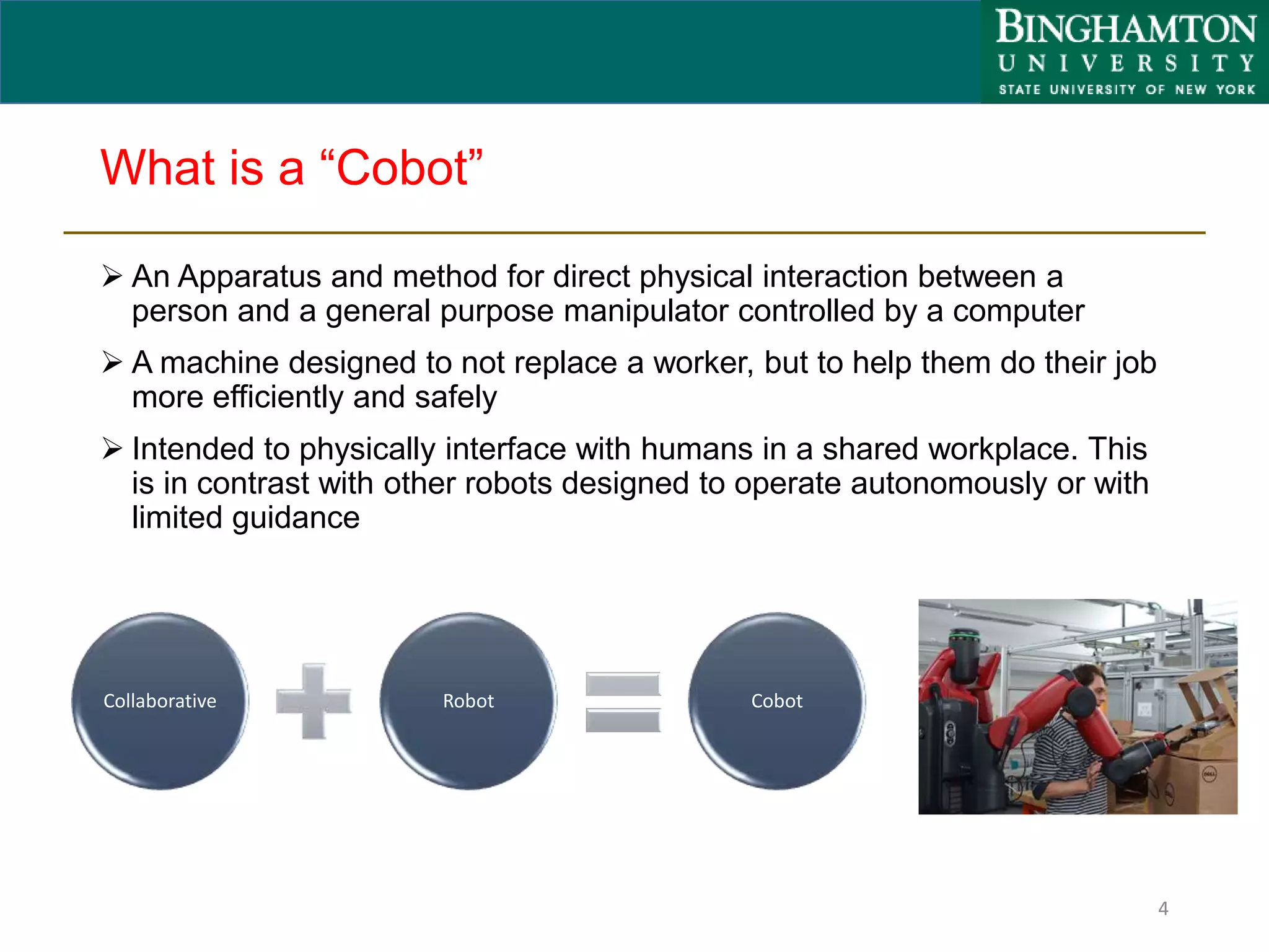
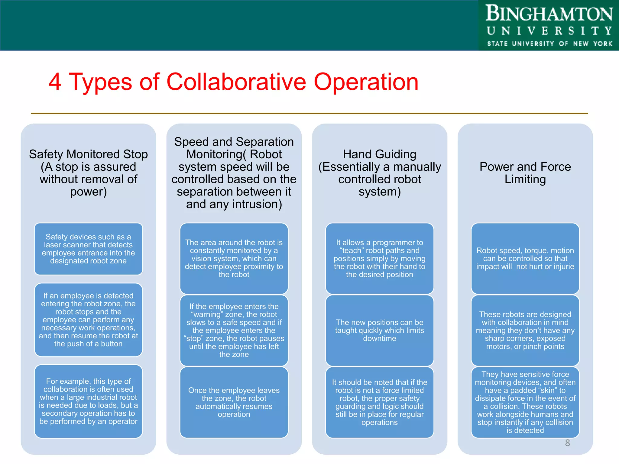
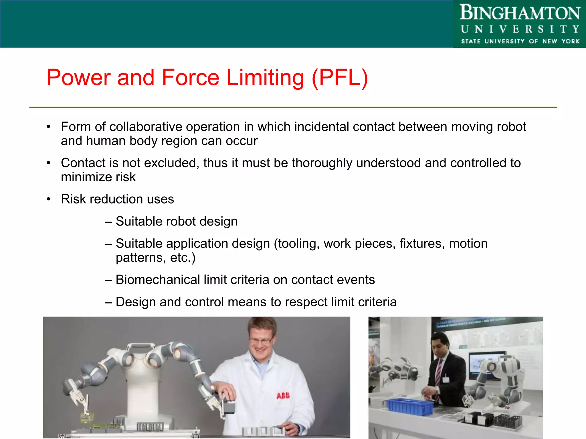
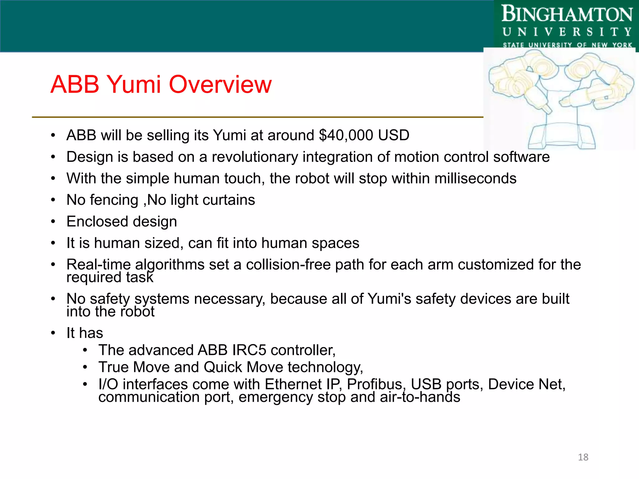
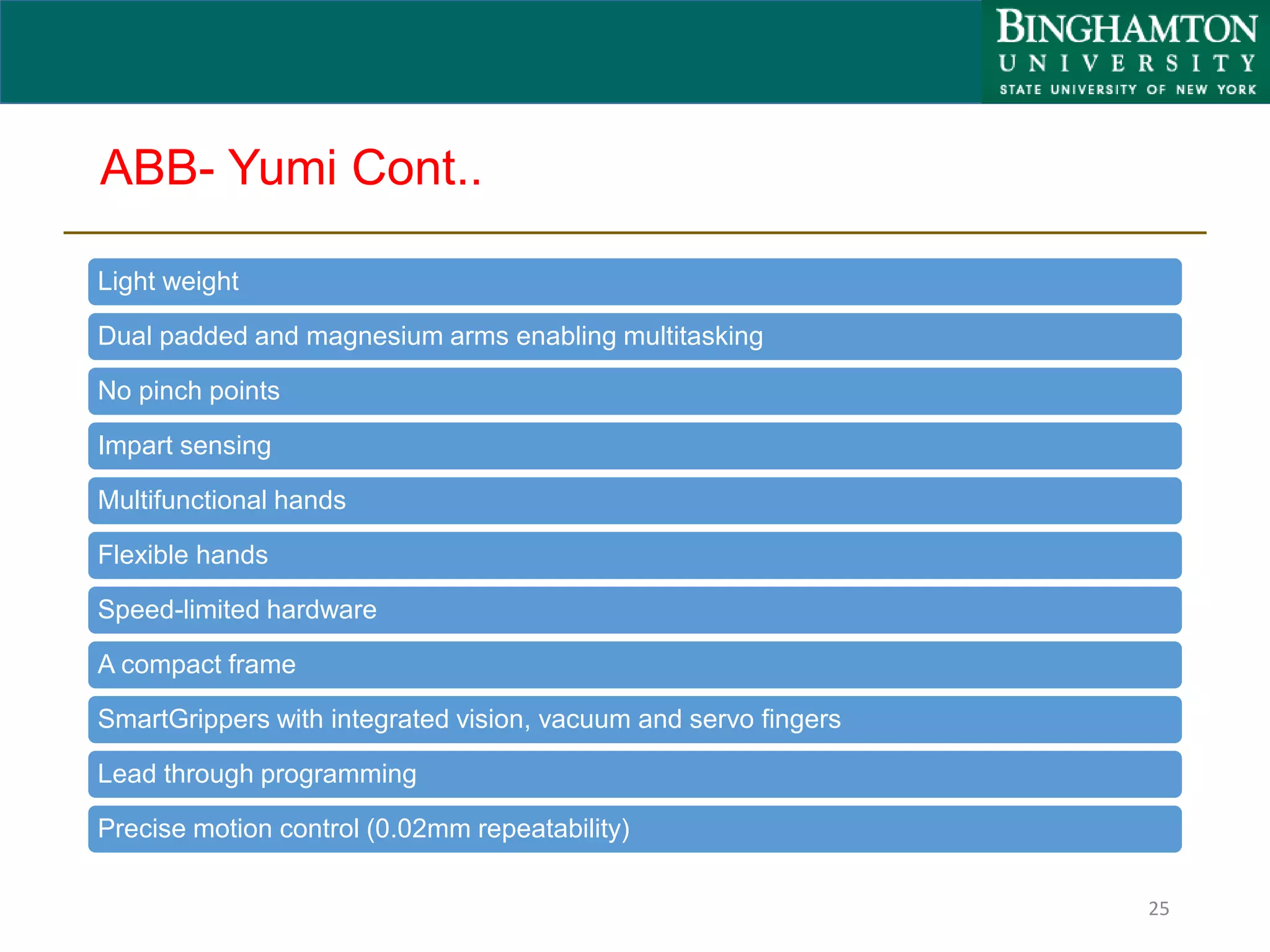
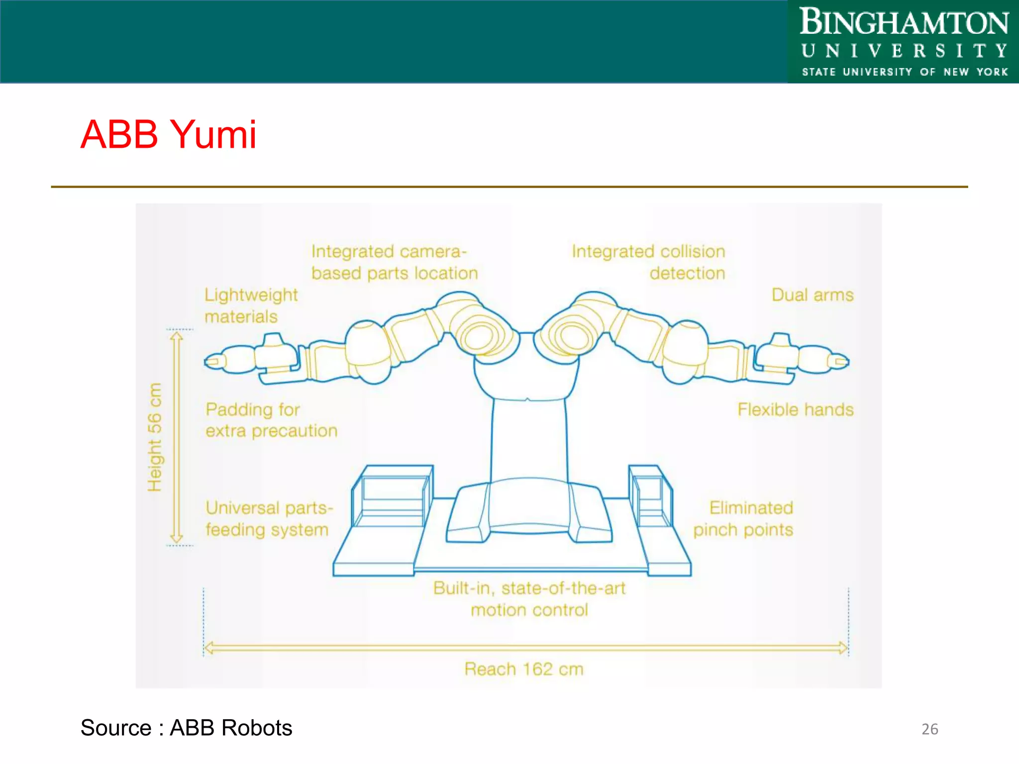
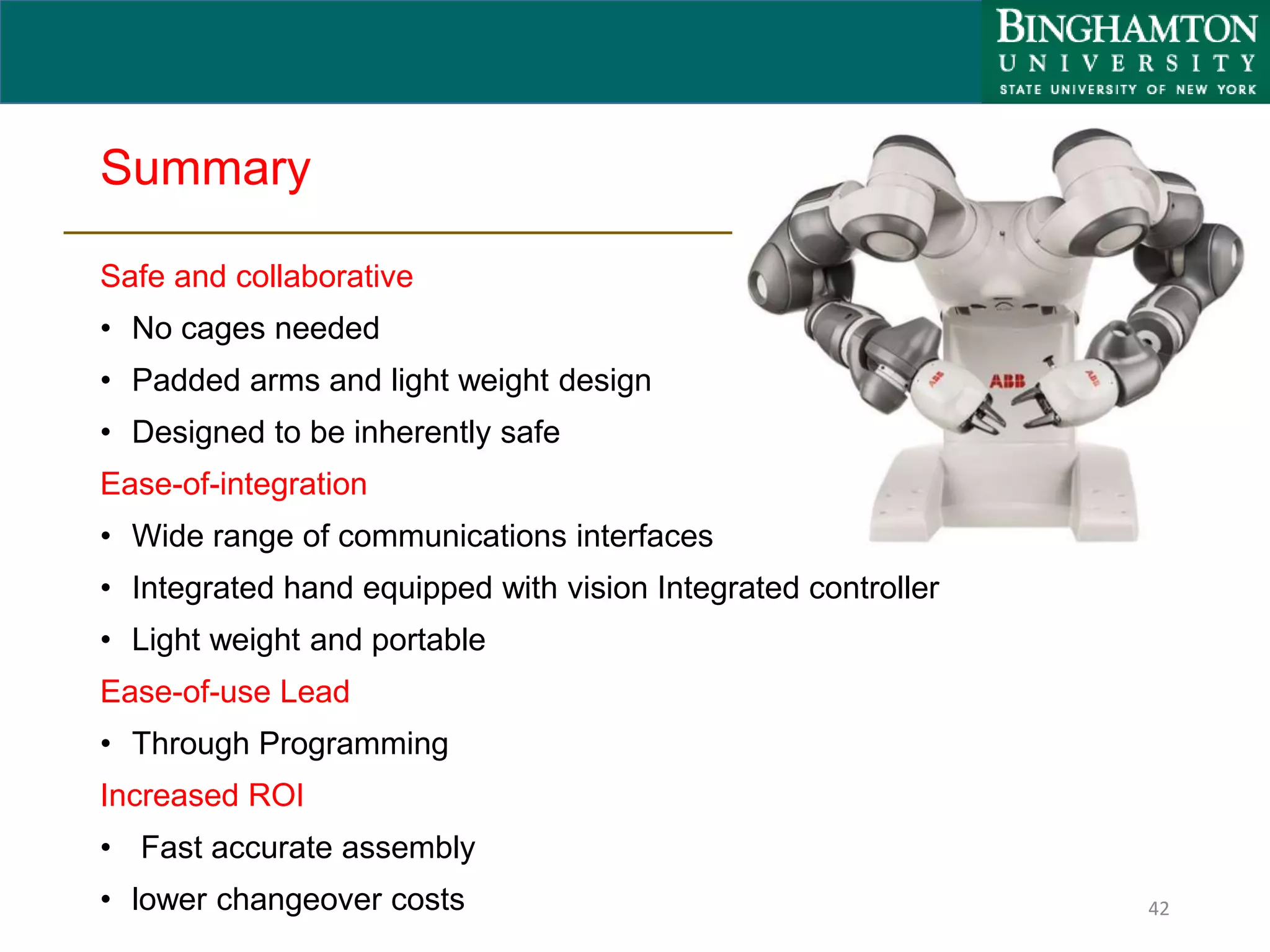
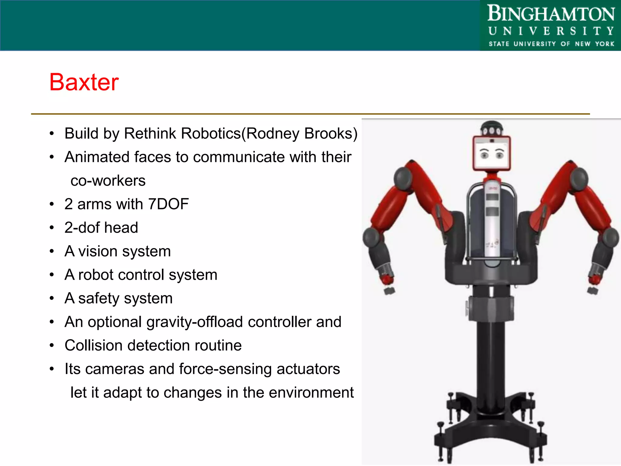
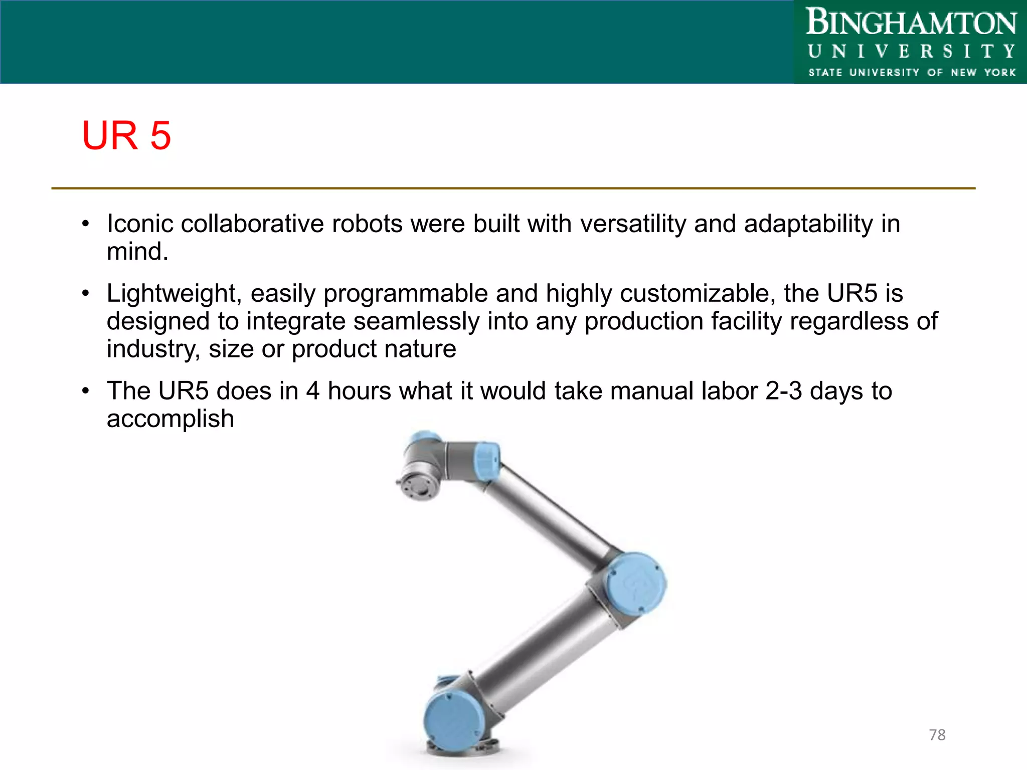
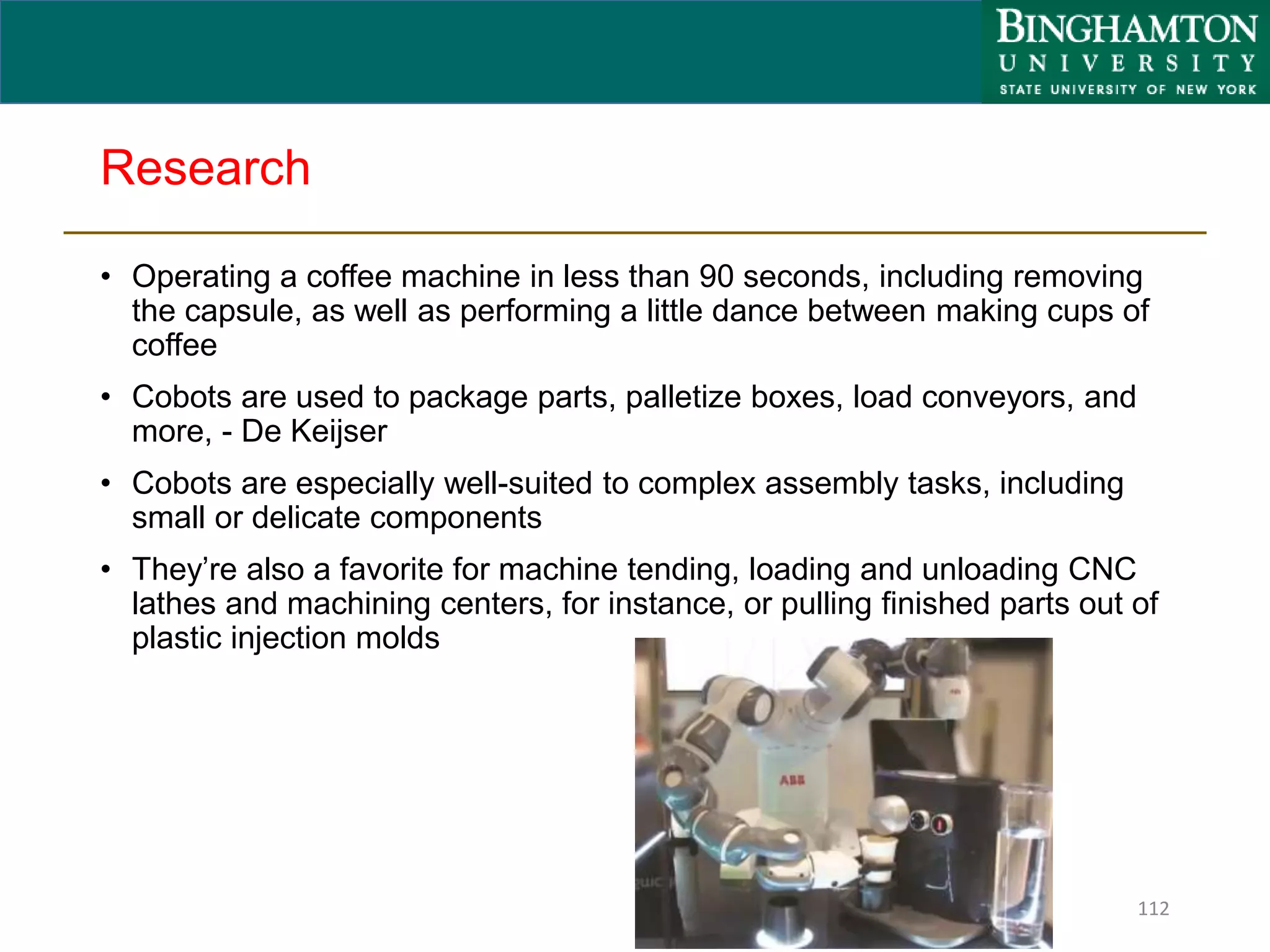
Collaborative robots, or cobots, are designed to safely work alongside humans in a shared workspace. This presentation discusses various cobots including ABB Yumi, Baxter, and UR5. It covers their key features such as safety mechanisms, ease of use, applications in assembly and material handling, and benefits for customers. Various collaborative operation modes are also presented, such as power and force limiting where contact with humans can occur safely.
Manufacturers are increasingly engaging in automation. In fact, 76% of manufacturers plan to invest in automation in the next three years according to a survey by Manufacturers Alliance for Productivity and Innovation (MAPI). The truth, however, remains that the majority of today’s manufacturing tasks cannot be addressed with traditional industrial automation.
Contents
Introduction to industrial robots
Application of robots in different areas
Application of robot in manufacturing industries
Types of industrial robots and their application
Advantages of industrial robots
Disadvantages of industrial robots
References
Re-Evaluating the Value and Market Positioning of Industrial CobotsLizzie Uhl
As one of the largest integrators in the nation, JR Automation sees nearly every type of request for automation. Because of that, we have gained a unique perspective on what cobot features end consumers are actually asking for and are willing to spend money on.
This presentation focuses on where cobots are being applied, where they can bring the most value to a business, and how their value can be fully realized.
Research Seminar on Cobots by Aleligne Yohannes Shiferaw.[M,Tech Robotics @ Vel Tech Rangarajan Dr.Sagunthala R&D Institute of Science and Technology.(India, Tamil Nadu, chennai)
Collaborative Robots 101: The Anatomy of a CobotSICK Inc
A collaborative robot—also referred to as a “cobot”— is a robot designed for interaction with a human. Check out the infographic to learn more about what makes a cobot and how the the technology is moving forward!
Robotics:-
Robotics is a branch of engineering that involves the conception, design, manufacture, and operation of machines assigned for specific high precision and repetitive tasks.
Following are the points that will be covered in this presentation:
1)Introduction to robotics
2)What is Robotics
3)History
4)Why Robotics?
5)Types of Robots
6)Components of Robots
7)Human Robot Interaction
8)Working of Robots
9)Advantages
10)Disadvantages
11)Applications
Slide show demonstrating pick and place robot and its parts.
Also effects are implanted in the slide.
It can be helpful for students for academic projects.
This Presentation is the Brief Introduction of the Adopted New Technology of Industry about the Robotics and also represent that What is actual Robot.
This is Basic Introduction about the Robotics.
Industrial Robots are changing and this presentation leads the user to the tools to control the hazards of collaborative and non-collaborative robotics.
A new service robot designed for cleaning tasks in home environments is introduced. System has three subsystems: electrical, software and mechanical of which micro controller, sensors (opponent and light) and motor are the electrical and mechanical subsystems respectively and the software subsystem is the brain of the robot. The cleaning robot uses a micro controller to detect obstacles and manipulates its direction as per the inputs. It is programmed to accept inputs to sense obstacles around it and control the robot to avoid any collisions. In case of an obstacle, or a potential collision, the micro controller controls the wheels of the robot by a motor driver to avoid collision. The vacuum cleaner at the bottom of the robot performs the cleaning process.
Student information management system project report ii.pdfKamal Acharya
Our project explains about the student management. This project mainly explains the various actions related to student details. This project shows some ease in adding, editing and deleting the student details. It also provides a less time consuming process for viewing, adding, editing and deleting the marks of the students.
KuberTENes Birthday Bash Guadalajara - K8sGPT first impressionsVictor Morales
K8sGPT is a tool that analyzes and diagnoses Kubernetes clusters. This presentation was used to share the requirements and dependencies to deploy K8sGPT in a local environment.
Hierarchical Digital Twin of a Naval Power SystemKerry Sado
A hierarchical digital twin of a Naval DC power system has been developed and experimentally verified. Similar to other state-of-the-art digital twins, this technology creates a digital replica of the physical system executed in real-time or faster, which can modify hardware controls. However, its advantage stems from distributing computational efforts by utilizing a hierarchical structure composed of lower-level digital twin blocks and a higher-level system digital twin. Each digital twin block is associated with a physical subsystem of the hardware and communicates with a singular system digital twin, which creates a system-level response. By extracting information from each level of the hierarchy, power system controls of the hardware were reconfigured autonomously. This hierarchical digital twin development offers several advantages over other digital twins, particularly in the field of naval power systems. The hierarchical structure allows for greater computational efficiency and scalability while the ability to autonomously reconfigure hardware controls offers increased flexibility and responsiveness. The hierarchical decomposition and models utilized were well aligned with the physical twin, as indicated by the maximum deviations between the developed digital twin hierarchy and the hardware.
Final project report on grocery store management system..pdfKamal Acharya
In today’s fast-changing business environment, it’s extremely important to be able to respond to client needs in the most effective and timely manner. If your customers wish to see your business online and have instant access to your products or services.
Online Grocery Store is an e-commerce website, which retails various grocery products. This project allows viewing various products available enables registered users to purchase desired products instantly using Paytm, UPI payment processor (Instant Pay) and also can place order by using Cash on Delivery (Pay Later) option. This project provides an easy access to Administrators and Managers to view orders placed using Pay Later and Instant Pay options.
In order to develop an e-commerce website, a number of Technologies must be studied and understood. These include multi-tiered architecture, server and client-side scripting techniques, implementation technologies, programming language (such as PHP, HTML, CSS, JavaScript) and MySQL relational databases. This is a project with the objective to develop a basic website where a consumer is provided with a shopping cart website and also to know about the technologies used to develop such a website.
This document will discuss each of the underlying technologies to create and implement an e- commerce website.
NUMERICAL SIMULATIONS OF HEAT AND MASS TRANSFER IN CONDENSING HEAT EXCHANGERS...ssuser7dcef0
Power plants release a large amount of water vapor into the
atmosphere through the stack. The flue gas can be a potential
source for obtaining much needed cooling water for a power
plant. If a power plant could recover and reuse a portion of this
moisture, it could reduce its total cooling water intake
requirement. One of the most practical way to recover water
from flue gas is to use a condensing heat exchanger. The power
plant could also recover latent heat due to condensation as well
as sensible heat due to lowering the flue gas exit temperature.
Additionally, harmful acids released from the stack can be
reduced in a condensing heat exchanger by acid condensation. reduced in a condensing heat exchanger by acid condensation.
Condensation of vapors in flue gas is a complicated
phenomenon since heat and mass transfer of water vapor and
various acids simultaneously occur in the presence of noncondensable
gases such as nitrogen and oxygen. Design of a
condenser depends on the knowledge and understanding of the
heat and mass transfer processes. A computer program for
numerical simulations of water (H2O) and sulfuric acid (H2SO4)
condensation in a flue gas condensing heat exchanger was
developed using MATLAB. Governing equations based on
mass and energy balances for the system were derived to
predict variables such as flue gas exit temperature, cooling
water outlet temperature, mole fraction and condensation rates
of water and sulfuric acid vapors. The equations were solved
using an iterative solution technique with calculations of heat
and mass transfer coefficients and physical properties.
Saudi Arabia stands as a titan in the global energy landscape, renowned for its abundant oil and gas resources. It's the largest exporter of petroleum and holds some of the world's most significant reserves. Let's delve into the top 10 oil and gas projects shaping Saudi Arabia's energy future in 2024.
Online aptitude test management system project report.pdfKamal Acharya
The purpose of on-line aptitude test system is to take online test in an efficient manner and no time wasting for checking the paper. The main objective of on-line aptitude test system is to efficiently evaluate the candidate thoroughly through a fully automated system that not only saves lot of time but also gives fast results. For students they give papers according to their convenience and time and there is no need of using extra thing like paper, pen etc. This can be used in educational institutions as well as in corporate world. Can be used anywhere any time as it is a web based application (user Location doesn’t matter). No restriction that examiner has to be present when the candidate takes the test.
Every time when lecturers/professors need to conduct examinations they have to sit down think about the questions and then create a whole new set of questions for each and every exam. In some cases the professor may want to give an open book online exam that is the student can take the exam any time anywhere, but the student might have to answer the questions in a limited time period. The professor may want to change the sequence of questions for every student. The problem that a student has is whenever a date for the exam is declared the student has to take it and there is no way he can take it at some other time. This project will create an interface for the examiner to create and store questions in a repository. It will also create an interface for the student to take examinations at his convenience and the questions and/or exams may be timed. Thereby creating an application which can be used by examiners and examinee’s simultaneously.
Examination System is very useful for Teachers/Professors. As in the teaching profession, you are responsible for writing question papers. In the conventional method, you write the question paper on paper, keep question papers separate from answers and all this information you have to keep in a locker to avoid unauthorized access. Using the Examination System you can create a question paper and everything will be written to a single exam file in encrypted format. You can set the General and Administrator password to avoid unauthorized access to your question paper. Every time you start the examination, the program shuffles all the questions and selects them randomly from the database, which reduces the chances of memorizing the questions.
An Approach to Detecting Writing Styles Based on Clustering Techniquesambekarshweta25
An Approach to Detecting Writing Styles Based on Clustering Techniques
Authors:
-Devkinandan Jagtap
-Shweta Ambekar
-Harshit Singh
-Nakul Sharma (Assistant Professor)
Institution:
VIIT Pune, India
Abstract:
This paper proposes a system to differentiate between human-generated and AI-generated texts using stylometric analysis. The system analyzes text files and classifies writing styles by employing various clustering algorithms, such as k-means, k-means++, hierarchical, and DBSCAN. The effectiveness of these algorithms is measured using silhouette scores. The system successfully identifies distinct writing styles within documents, demonstrating its potential for plagiarism detection.
Introduction:
Stylometry, the study of linguistic and structural features in texts, is used for tasks like plagiarism detection, genre separation, and author verification. This paper leverages stylometric analysis to identify different writing styles and improve plagiarism detection methods.
Methodology:
The system includes data collection, preprocessing, feature extraction, dimensional reduction, machine learning models for clustering, and performance comparison using silhouette scores. Feature extraction focuses on lexical features, vocabulary richness, and readability scores. The study uses a small dataset of texts from various authors and employs algorithms like k-means, k-means++, hierarchical clustering, and DBSCAN for clustering.
Results:
Experiments show that the system effectively identifies writing styles, with silhouette scores indicating reasonable to strong clustering when k=2. As the number of clusters increases, the silhouette scores decrease, indicating a drop in accuracy. K-means and k-means++ perform similarly, while hierarchical clustering is less optimized.
Conclusion and Future Work:
The system works well for distinguishing writing styles with two clusters but becomes less accurate as the number of clusters increases. Future research could focus on adding more parameters and optimizing the methodology to improve accuracy with higher cluster values. This system can enhance existing plagiarism detection tools, especially in academic settings.
NO1 Uk best vashikaran specialist in delhi vashikaran baba near me online vas...Amil Baba Dawood bangali
Contact with Dawood Bhai Just call on +92322-6382012 and we'll help you. We'll solve all your problems within 12 to 24 hours and with 101% guarantee and with astrology systematic. If you want to take any personal or professional advice then also you can call us on +92322-6382012 , ONLINE LOVE PROBLEM & Other all types of Daily Life Problem's.Then CALL or WHATSAPP us on +92322-6382012 and Get all these problems solutions here by Amil Baba DAWOOD BANGALI
#vashikaranspecialist #astrologer #palmistry #amliyaat #taweez #manpasandshadi #horoscope #spiritual #lovelife #lovespell #marriagespell#aamilbabainpakistan #amilbabainkarachi #powerfullblackmagicspell #kalajadumantarspecialist #realamilbaba #AmilbabainPakistan #astrologerincanada #astrologerindubai #lovespellsmaster #kalajaduspecialist #lovespellsthatwork #aamilbabainlahore#blackmagicformarriage #aamilbaba #kalajadu #kalailam #taweez #wazifaexpert #jadumantar #vashikaranspecialist #astrologer #palmistry #amliyaat #taweez #manpasandshadi #horoscope #spiritual #lovelife #lovespell #marriagespell#aamilbabainpakistan #amilbabainkarachi #powerfullblackmagicspell #kalajadumantarspecialist #realamilbaba #AmilbabainPakistan #astrologerincanada #astrologerindubai #lovespellsmaster #kalajaduspecialist #lovespellsthatwork #aamilbabainlahore #blackmagicforlove #blackmagicformarriage #aamilbaba #kalajadu #kalailam #taweez #wazifaexpert #jadumantar #vashikaranspecialist #astrologer #palmistry #amliyaat #taweez #manpasandshadi #horoscope #spiritual #lovelife #lovespell #marriagespell#aamilbabainpakistan #amilbabainkarachi #powerfullblackmagicspell #kalajadumantarspecialist #realamilbaba #AmilbabainPakistan #astrologerincanada #astrologerindubai #lovespellsmaster #kalajaduspecialist #lovespellsthatwork #aamilbabainlahore #Amilbabainuk #amilbabainspain #amilbabaindubai #Amilbabainnorway #amilbabainkrachi #amilbabainlahore #amilbabaingujranwalan #amilbabainislamabad
Water billing management system project report.pdfKamal Acharya
Our project entitled “Water Billing Management System” aims is to generate Water bill with all the charges and penalty. Manual system that is employed is extremely laborious and quite inadequate. It only makes the process more difficult and hard.
The aim of our project is to develop a system that is meant to partially computerize the work performed in the Water Board like generating monthly Water bill, record of consuming unit of water, store record of the customer and previous unpaid record.
We used HTML/PHP as front end and MYSQL as back end for developing our project. HTML is primarily a visual design environment. We can create a android application by designing the form and that make up the user interface. Adding android application code to the form and the objects such as buttons and text boxes on them and adding any required support code in additional modular.
MySQL is free open source database that facilitates the effective management of the databases by connecting them to the software. It is a stable ,reliable and the powerful solution with the advanced features and advantages which are as follows: Data Security.MySQL is free open source database that facilitates the effective management of the databases by connecting them to the software.
Understanding Inductive Bias in Machine LearningSUTEJAS
This presentation explores the concept of inductive bias in machine learning. It explains how algorithms come with built-in assumptions and preferences that guide the learning process. You'll learn about the different types of inductive bias and how they can impact the performance and generalizability of machine learning models.
The presentation also covers the positive and negative aspects of inductive bias, along with strategies for mitigating potential drawbacks. We'll explore examples of how bias manifests in algorithms like neural networks and decision trees.
By understanding inductive bias, you can gain valuable insights into how machine learning models work and make informed decisions when building and deploying them.
Industrial Training at Shahjalal Fertilizer Company Limited (SFCL)MdTanvirMahtab2
This presentation is about the working procedure of Shahjalal Fertilizer Company Limited (SFCL). A Govt. owned Company of Bangladesh Chemical Industries Corporation under Ministry of Industries.
2. Agenda
• Introduction to Cobots
• Cobot vs Robot
• Industrial Robots vs Collaborative Robots
• 4 Types of Collaborative Operation
• ABB Yumi
• Baxter
• UR 5
• Cobots in Education
• Research Options
• Cloud Robotics
2
3. Introduction
Origin – 1996 Northwestern University
Professors Colgate and Peshkin
Originally called – Intelligent Assist Devices
Cobots – 1996
• Programmable Constraint Machine that
highlights a passive and safe method for
allowing a computer to create a
constraint surface for a human user
(and optionally a payload) to follow
3
4. What is a “Cobot”
An Apparatus and method for direct physical interaction between a
person and a general purpose manipulator controlled by a computer
A machine designed to not replace a worker, but to help them do their job
more efficiently and safely
Intended to physically interface with humans in a shared workplace. This
is in contrast with other robots designed to operate autonomously or with
limited guidance
4
Collaborative Robot Cobot
5. What is a “Cobot”
Safely works alongside workers without safety cages
• Works at human cadence
• Uses force feedback or other sensing methods to prevent injury
• Utilizes safe end-effectors
Does simple, repetitive tasks
Easily programmed -- and re-programmed -- by workers
• Programmable in minutes
• Usable by shop floor supervisor or CNC operator
• Learn by doing teach mode
• No programming required
Applications
• Machine Tending (CNC loading)
• Tester Operation (In Circuit Test, Consumer Electronics Test)
• Packaging (Sterile Food Handling)
5
6. Cobot vs Robot
• Safer compared to robots
• Flexible and easy to use
• Understands people and
environment
• Tasks are performed similar to
human way
• Can be trained by
demonstration
• No/minimum integration
required
• Affordable
• Potential danger to human
safety
• High precision and
repeatability
• Unaware of surrounding
• Definite operations for tasks
completion are required
• Need expert programmers
• Integration is costly
• Expensive
6
Cobot Robot
8. 4 Types of Collaborative Operation
Safety Monitored Stop
(A stop is assured
without removal of
power)
Safety devices such as a
laser scanner that detects
employee entrance into the
designated robot zone
If an employee is detected
entering the robot zone, the
robot stops and the
employee can perform any
necessary work operations,
and then resume the robot at
the push of a button
For example, this type of
collaboration is often used
when a large industrial robot
is needed due to loads, but a
secondary operation has to
be performed by an operator
Speed and Separation
Monitoring( Robot
system speed will be
controlled based on the
separation between it
and any intrusion)
The area around the robot is
constantly monitored by a
vision system, which can
detect employee proximity to
the robot
If the employee enters the
“warning” zone, the robot
slows to a safe speed and if
the employee enters the
“stop” zone, the robot pauses
until the employee has left
the zone
Once the employee leaves
the zone, the robot
automatically resumes
operation
Hand Guiding
(Essentially a manually
controlled robot
system)
It allows a programmer to
“teach” robot paths and
positions simply by moving
the robot with their hand to
the desired position
The new positions can be
taught quickly which limits
downtime
It should be noted that if the
robot is not a force limited
robot, the proper safety
guarding and logic should
still be in place for regular
operations
Power and Force
Limiting
Robot speed, torque, motion
can be controlled so that
impact will not hurt or injurie
These robots are designed
with collaboration in mind
meaning they don’t have any
sharp corners, exposed
motors, or pinch points
They have sensitive force
monitoring devices, and often
have a padded “skin” to
dissipate force in the event of
a collision. These robots
work alongside humans and
stop instantly if any collision
is detected
8
9. What is End Effectors ?
• In robotics, an end effector is a device or tool that's connected to the end
of a robot arm where the hand would be
• The end effector is the part of the robot that interacts with the
environment
• End effectors used in manufacturing include
9
anti-collision
sensors
brushes cameras cutting tools
drills grippers magnets sanders
screw
drivers
spray guns
vacuum
cups
welding
guns
10. Actuators
• An actuator is the actual mechanism that enables the effector to
execute an action
• Typically include: –
• Electric motors
• Hydraulic cylinders
• Pneumatic cylinders
10
11. Effectors and Actuators
• Two basic ways of using effectors
– to move the robot around
⇒ locomotion
– to move other object(s) around
⇒ manipulation
• Thus robots are divided into
– mobile robots
– manipulator robots
11
12. Degrees of freedom and Actuators
• Most simple actuators control one degree of freedom
• i.e., a single motion
• E.g., up-down; left-right; in-out
• Example:
– Motor shaft
– Sliding part on a plotter
12
13. Degrees of freedom and Effectors
• How many degrees of freedom a robot has is very important in
determining how it can affect its world, and therefor how well, if at
all, it can accomplish its task
Both sensors and effectors must be well-matched
to the robot’s task!!
13
14. Servo Motors
• Servo motors = motors that can turn to a
specific position (and stop)
• Basic DC motors cannot do this
• Servo motors are constructed out of DC motors
by adding:
– gear reduction
– position sensor for motor shaft
– electronic circuit to control motor’s
operation
14
15. Servo motors: Control
• Most have movement reduced to 180º (instead of full 360 º)
• Motor driven with a waveform that specifies the desired angular position
of the shaft within that 180 º range
• Waveform is given as a series of pulses, within a pulse-width modulated
signal
• Thus the width (i.e., length) of the pulse specifies the control value for the
motor (i.e., how the shaft should turn)
15
16. Power and Force Limiting (PFL)
• Form of collaborative operation in which incidental contact between moving robot
and human body region can occur
• Contact is not excluded, thus it must be thoroughly understood and controlled to
minimize risk
• Risk reduction uses
– Suitable robot design
– Suitable application design (tooling, work pieces, fixtures, motion
patterns, etc.)
– Biomechanical limit criteria on contact events
– Design and control means to respect limit criteria
16
17. PFL – Possible Misconceptions
• Use of collaborative robots featuring PFL does not mean
– Simply remove fences without further considerations
– “Safe” robot will render entire application “safe”
– Requires a higher safety performance level than standard
industrial robots
– Will be too slow for productive applications
17
18. ABB Yumi Overview
• ABB will be selling its Yumi at around $40,000 USD
• Design is based on a revolutionary integration of motion control software
• With the simple human touch, the robot will stop within milliseconds
• No fencing ,No light curtains
• Enclosed design
• It is human sized, can fit into human spaces
• Real-time algorithms set a collision-free path for each arm customized for the
required task
• No safety systems necessary, because all of Yumi's safety devices are built
into the robot
• It has
• The advanced ABB IRC5 controller,
• True Move and Quick Move technology,
• I/O interfaces come with Ethernet IP, Profibus, USB ports, Device Net,
communication port, emergency stop and air-to-hands
18
19. Enclosed design
• Enclosed design allows all wiring and air to go through the inside
of the robot
• Reduced maintenance
• Less risk of cable and air hose damaged
• Can be used in confined spaces
• Easy to keep clean
• No risk of dust collecting on cables
19
21. IRC5
• The ABB IRC5(Industrial robot controller)is a fifth generation robot
controller that combines motion control, flexibility, modularity, usability,
application interfaces, and safety
• Motion control is the part of automation that handles the kinematics and
the electromechanical portion of machines in a deliberate and controlled
manner.
• The primary components of a motion control system are the controller
and the power amplifier
21
22. ABB- Yumi technical data
Payload 0.5 kg per arm
Reach 559 mm
Accuracy 0.02 mm
Footprint 339 mm * 497 mm
Mounting
interface
Foot interface
Weight 38 kg
Mounting
position
Table
Temperature 5 C – 40 C deg
IP Protection IP 30
Clean
room/Food
grade
ISO lvl 5
22
IRB 14000 – 0.5/0.5
23. Maximum velocity
Motion Range Max. Velocity
Axis 1 Rotation +168.5° to -168.5° 180 °/s
Axis 2 Arm +43.5° to -143.5° 180 °/s
Axis 7 Rotation +168.5° to -168.5° 180 °/s
Axis 3 Arm +80° to -123.5° 180 °/s
Axis 4 Wrist +290° to -290° 400 °/s
Axis 5 Bend +138° to -88° 400 °/s
Axis 6 Turn +229° to -229° 400 °/s
23
24. Key features
• Maximum load per arm: capacity with grippers: 239 g
• Maximum load per arm: capacity without grippers: 500 g
• Position repeatability: ±0.02 mm
• Workspace radius 560mm
• Programmable via rapid on HMI pendant or Robot studio
• Device Net Master/Slave, profibus adapter, wan, lan, Profinet and air
supply (0.6 MPa)
24
25. ABB- Yumi Cont..
Light weight
Dual padded and magnesium arms enabling multitasking
No pinch points
Impart sensing
Multifunctional hands
Flexible hands
Speed-limited hardware
A compact frame
SmartGrippers with integrated vision, vacuum and servo fingers
Lead through programming
Precise motion control (0.02mm repeatability)
25
27. Pinch Points
• A point in between moving and stationary parts of a machine
where an individual's body part may become caught, leading to
injury
27
28. Customer benefits
• Padded arms - Including internal wiring and air
• Integrated controller - New in ABB portfolio
• Lightweight construction - Makes the robot portable
• Ease-of-use - Lead Through Programing
• Enclosed design - Lower maintenance
• Integrated vision and integrated hands - Built in to product and easy to
integrate
• Safety certified - Certified by an independent body
• Dual arm – Multi-tasking
28
29. 1. Padded arms
• Adds to safety of operators if there is an unlikely contact during operation
• The robot can be run faster due to added protection
• Faster robot means the ROI will be greater
29
30. 2. Integrated Controller
• Embedded controller based on IRC5
• Portable (38kg)
• External connectors
• Built-in 8 in /8 out
• Saves working space
• Better cell layout
• Equipment can be placed closer to,
or around, robot without interference
• Robot is more streamlined and
easy to relocate
• No floor cables or control cables
30
31. 3. Lightweight construction
• Makes the robot portable
• Increases safety of the robot
• Smaller frame to mount the robot
31
32. 4. Ease-of-use
• Lead-Through Programming makes the programming easy
• Integrated vision can pick parts without fixture
• Can use Yumi App for programming on a wireless tablet
• Standard IRC5 system as other ABB robots for uniform programming
environment
• Can use Robot Studio for offline programming and simulation
32
33. 5. Enclosed design
Enclosed design allows all wiring and air to go through the inside of the
robot
– Reduced maintenance
– Less risk of cable and air hose damaged
– Can be used in confined spaces
– Easy to keep clean
– No risk of dust collecting on cables
33
34. 6. Integrated vision and integrated hands
Integrated vision
• Cameras embedded in gripper
• Integrated hands makes it
possible to use the hand for
vison guided picking
• Can be used for simple
inspection
Integrated hands
• No need to design your own
hand
• Multi-option hand with five
options
• Integrated communications
and air
• Servo
• Vacuum
• Camera
34
35. 7. Safety certified
• No need to certify the robot
• Can be included in your risk assessment of the cell
• Independent body has certified the robot
• PL b Cat b
35
36. 8. Dual arm
• Possible to achieve contact force assembly between arms
• Can process two tasks at the same time
• Operation similar to a human assembling
36
37. Protection
IP Protection
IP 30 (Standard)
– It is sufficient for
assembly
37
ESD Protection
It makes it possible to
handle static sensitive
parts
Perfect for electronic
assembly
No need to test as it is
certified robot
Cleanroom
Yumi IRB14000
has been certified
by Fraunhofer
institute (IPA) in
Germany to fulfil
Cleanroom
requirements of
ISO 5 level
38. Key applications and segments
• Electronics
assembly
• Automotive
Electronics
• Consumer
products and
general industry
• Medical
Equipment
• Toys
• Other small parts
manufacturing
Segments
• Harsh
environments
• Handling naked
food
Applications
not suitable for
• Small Parts
Assembly
• Collaborative
Assembly
• Accurate and fast
assembly
• Testing and
packaging
• Material handling
• Inspection
Applications
Suitable for
38
39. Vision Guided-Assembly
• Vision included in hands as package
• Vision can also be connected to robot for external devices like flex
feeders
• This makes it possible to have less jigging and move to a more
• Flexible cell design
39
40. Small Parts Assembly using the Flex Feeders
and ABB gripper
• Gripper and Flex Feeders (possible only in Yumi) make it possible to have
a complete solution from part handling to assembly
• Odd sorted parts can be placed in Flex Feeders and presented to the
robot in a two dimensional plane
40
41. Small Parts Material Handing
• After the assembly process is
complete the robot can place
the finished product in box
ready for shipment
• Yumi working side-by-side
handing finished parts to be
packed
41
42. Summary
Safe and collaborative
• No cages needed
• Padded arms and light weight design
• Designed to be inherently safe
Ease-of-integration
• Wide range of communications interfaces
• Integrated hand equipped with vision Integrated controller
• Light weight and portable
Ease-of-use Lead
• Through Programming
Increased ROI
• Fast accurate assembly
• lower changeover costs 42
43. Baxter
• Build by Rethink Robotics(Rodney Brooks)
• Animated faces to communicate with their
co-workers
• 2 arms with 7DOF
• 2-dof head
• A vision system
• A robot control system
• A safety system
• An optional gravity-offload controller and
• Collision detection routine
• Its cameras and force-sensing actuators
let it adapt to changes in the environment
43
44. Baxter
• 7-dof robot arms are classified as kinematically-redundant i.e. possessing
more joint freedoms than necessary to operate fully in the desired
Cartesian space
• Specifically, Baxter has n = 7 single-dof revolute (R) joints, which is one
greater than the m = 6 Cartesian dof (3 translations and 3 rotations) for
general trajectories (n>m)
• The Baxter designers consider a 2-dof shoulder, a 2-dof elbow, and a 3-
dof wrist
44
45. Baxter 7-dof Left Arm R Joints
Joint Name Joint Motion
S0 Shoulder roll
S1 Shoulder roll
E0 Elbow roll
E1 Elbow roll
W0 Wrist roll
W1 Wrist roll
W2 Wrist roll
45
46. Technical Specifications
46
• Baxter is about 3’ tall (around 6’ tall with stationary pedestal) and
• Weighs 165 lbs. (306 lbs. including the pedestal).
• Baxter has a 103” ‘wingspan’ and
• A 32” x 36” pedestal base
• Both 7-dof arms include angle position and joint torque sensing
• For Cartesian sensors, there are
• Three integrated cameras,
• Plus sonar,
• Accelerometers and
• Range-finding sensors.
• Each Baxter arm has a
• Temperature sensor,
• Allowing human fingers to be detected for lead-through programming
47. Technical Specifications Cont..
47
• The maximum payload, including the end-effector in the safety-enabled
mode, is 2.3 kg
• This increases to about 25 kg with safety disabled
• The joint sensor resolution for each of the 7-dof arm joints, right and left,
is 14 bits for 360 degrees , which works out to 0.02197 degrees per
encoder count
• The onboard computer consists of a third-generation Intel Core i7-3770
8MB 3.4 GHz processor with HD4000 Graphics, 4GB 1600 MHz DDR3
memory, and 128 GB solid state hard drive
• The camera has a maximum resolution of 1280 x 800 pixels (640 x 400
pixels effective resolution), with a 30 fps frame rate and 1.2 mm focal
length
• The animated face flat screen has a resolution of 1024 x 600 pixels
50. Turning on Baxter
• Press the white power button on the lower left back of the robot
• The lights on the head turn on, and the main screen appears on the
Baxter display
50
51. How to Interact
with Baxter
Using the Training Cuffs
• Use the training cuffs to move the arms, to
manipulate the state of the grippers, and
secondarily, to select on-screen options
• Training cuff switch: Squeeze this switch at
the indentation in the cuff to move the
robot’s arm. When this switch is squeezed,
the blue indicator on the arm’s navigator
button lights up
• Grasp button: Press to toggle a parallel
gripper open or closed, or a vacuum gripper
on or off
• Action button: Press to select items on the
display screen. Create waypoints, Hold
actions; select, copy, or move actions on the
task map; create a new subtask; add/create
landmarks; outline a visual search
51
52. Navigating the
Screens
• Use the navigator on either of the arms to
scroll to and interact with options on the
screen. When you press the OK button (2)
(or the action button on the cuff), the white
indicators on the navigator light up
• Back button: Press to exit the current
screen and return to the previous screen.
Will also cancel the last action
• Knob: Scroll the knob to move between on-
screen options. Press the knob (OK) to
select an option
• OK indicator light: When the action button
on the cuff or the OK button on the
navigator is pressed, the white indicator
around the knob lights up
• Rethink button: Press to display options
for the current screen
• Training cuff indicator: When the switch
on the cuff is squeezed, the blue indicators
along the top and bottom edge of the
navigator light up
52
53. Moving the Arms
• To move an arm, squeeze the cuff at the indentation just above the other
buttons, and push or pull the arm to the location you want
• Squeezing the cuff releases the tension and resistance in the arm,
making it easier to manipulate
• With its seven degrees of freedom—an incredible amount of flexibility—
Baxter enhances arm stability by attempting to fix its elbow in position
whenever the lower arm is moved
• Note: When the switch is pressed, the blue indicator lights illuminate on
the corresponding navigators on the arm and torso
53
54. Elbow and cuff
• When grasping the training cuff, you can
move the arms by either repositioning the
lower arm or changing the height of the
elbow
• To move the lower arm: While
squeezing the cuff (1), move the robot’s
arm to the desired location
• To move the elbow: By design, the
elbow (2) will try to maintain its current
height and will spring back if you do not
actively reset it. While squeezing the cuff,
move the elbow to the desired position.
Continue to hold the elbow at the new
location, and release the cuff. This will
reset the elbow at the new position.
54
55. Grasping Objects
• Training involves showing Baxter how to pick up and place objects
• To grasp an object: Position the gripper over the object, press Grasp
• To release an object: With an object in the robot's hand, press Grasp
• To open or close the gripper without creating a pick or place: Without
an object in hand, press Grasp twice quickly
55
56. Eye Expressions
• Baxter displays one of six eye expressions in response to what it is doing
or what it senses happening in its environment
56
57. Expressions
• The surprised expression is
emphasized with an orange
background when Baxter is
working and unexpectedly detects
someone has entered its space
(currently, this only happens when
a safety mat is connected and
stepped on); Baxter also
automatically slows its movement
• Attention Ring The attention ring
lights appear in clusters of two or
three when Baxter detects
movement. When Baxter is
confused, the yellow lights in the
ring appear and flash
simultaneously
57
59. “Light Bulb” Tips
• When you see a "light bulb" symbol on a screen, that means there is a tip
(or tips) on how to use that functionality. Select the light bulb to display
the tip. (These tips are available on the Modify Waypoints Screen, the
Advanced Screen, and the Action Practice screens. )
59
60. Move the Arm
Grab anywhere along Baxter’s arm and
push and pull on it slightly to feel its
resistance. Now, grab the indented portion
of the training cuff, the part between
Baxter’s wrist and grippers, and squeeze it
just above the buttons on either side.
Baxter is now in “Zero G” mode and you
can now move the arm easily
Release the training cuff and the arm
becomes (semi-) rigid again. Note that the
arm stays in the location and orientation it
was in when you stopped squeezing the
training cuff. The location and orientation
of the arm (its shoulder, elbow, wrist, and
so on) is called its pose
60
61. THE NAVIGATOR
• On both of Baxter’s arms, and on either side of Baxter’s torso, is the
Navigator, a set of buttons and a knob you use to make selections on
Baxter. The selections you make on the Navigator are shown on Baxter’s
display
61
62. Create a New Task
• The job you train a robot to perform is called a task. A task can be very
simple, like the pick and place you’re about to create, or much more
complicated, involving multiple pick and place locations, a variety of poses,
and sending and receiving signals from other machines and devices
• In this module, you will use the selector knob to scroll through options on the
robot’s display and press it to make a selection. We refer to pressing the
scroll knob to make a selection as “pressing the OK button” or sometimes,
“press OK on the Navigator.”
• You press the Back button on the Navigator when you want to return to the
previous screen
• Scroll the knob to reveal the main button bar and stop scrolling when you
reach the New Task icon
Press OK on the Navigator. Baxter displays a blank Task Map
62
63. Create a New Task Cont..
The Task Map is a top-down view of the Baxter workspace (a.k.a. work
envelope)
• Blue icon - the location of the end of the right arm
• Green icon - the location of the end of the left arm
• Dark gray shaded area - where the arm can reach
• Indicators along left side - reflect the current state of each joint in relation to
its hard stop limit. Bottom indicator represents the joint closest to the robot’s
base. Indicator on top is the training cuff. Other joints are represented in
order between the cuff and the base
• Bar on right - task name
63
64. 64
• Move Baxter’s right arm in Zero G by pressing and holding the training
cuff. Watch the blue icon move on screen in response to the movement of
the arm
• Notice that when a joint moves closer to its limit, the indicator lines turn
from gray to red. If an indicator turns completely red, you have reached
the joint’s limit. If the blue arm icon itself turns gray, you will be unable to
train an action until you move the arm to a better position. This may be
because one of the joints is at a hard limit, which would prevent the robot
from performing an action
• A gray arm icon could also mean the arm is too close to the head. The
robot has anti-collision software that protects the robot from coming into
contact with itself. You can see this in action by trying to push the end of
the arm into the head while in zero G
65. Grasp an Object
• There are two buttons on the training cuff we have not used to this point.
The oval button is called the Grasp button. The round button is the Action
button
• The Grasp button makes the gripper open and close. The Action button
brings up additional menus on the Task Map. Press each button now to
see the effect of each.
• The robot grasps the object and the Task Map displays a Pick icon in the
location where the part was picked. Notice that the top left corner of the
Pick Icon displays 1A. That means the action you just trained is the first
action in the first subtask
65
66. Grasp an Object
• With the part in the robot’s gripper, move the right arm (in Zero G) to where you
would like to place it. Press the Grasp button to release the part from the gripper. A
Place icon is displayed on the Task Map where you trained the place, along with a
subtask number and sequence letter
66
Task Map will now look something like this
67. 67
• Return the object to the spot where you trained the pick. Press the Back
button on the Navigator to display the Main Screen, then scroll to and
select Reset to start the task. The arm moves to the pick location, picks
the part, moves to the place location, places the part, then automatically
resets
Congratulations! You have just trained your first task using Baxter!
• Press the Rethink button on the Navigator and select Rename. Then
name this task “Task 1” so you can refer back to it as you continue
through this guide
68. Labeling Actions
• Generally, the robot’s tasks involve Pick actions followed by Place
actions. To make it easier to distinguish one action from another, actions
are labeled on the Task Map with the subtask number and appended with
a letter.
• For example, if subtask 1 includes a Pick>Hold>Hold>Place, the actions
on the Task Map will be labeled:
-- Pick 1A
-- Hold 1B
-- Hold 1C
-- Place 1D
• A subtask is a routine, or sequence of actions, the robot will perform
within a task. A task can have one or multiple subtasks. As with actions,
subtasks can have counts and signals associated to them 68
69. Main Screen
1. Current task name
2. Current task options
• Run – run the task from where the task left off
• Reset – reset the count, and restart the task
from the beginning
• Modify – open the task map so the user can
make changes to the task’s elements.
3. Baxter eyes – The robot uses eye expressions to
communicate to users in a familiar way by glancing in
the direction in which it’s about to move. Baxter also has
other expressions to communicate its different states
4. Main options:
• New – create a task
• Tasks – opens the task gallery, a visual list of
existing saved tasks
• Settings – open Baxter administration and
hardware settings
• Power – open Baxter power options: Sleep, Restart,
Shutdown, and Lock/ Unlock
69
70. TASK MAP ATTRIBUTES
1. Baxter workspace.
2. Joint limit indicators - display the current state
of each joint of the active arm in relation to its
mechanical limit.
3. Real time location of end of right arm.
4. Weight label - displays the part weight
designated for a particular action. (Here, a .7kg
weight has been designated for Pick action 1A.
5. Pick action icon - a point in the robot’s
workspace where the end of arm tooling will
attempt to pick an object.
6. Task name - name given to the task currently
being modified.
7. Place action icon - a point in the robot’s
workspace where the end of arm tooling will
release a picked object.
8. Location of end of arm - icon that represents
the real-time location of the end of the arm.
9. Hold Action - a point in the robot’s workspace
where the end of the arm will move through, or
wait at, when the task is run 70
71. 71
Pressing the Rethink button while on the Task Map opens the task map button bar
• Back – Close the button bar and return focus to the task map. This can also be done using the
Back button on the Navigator
• Run – Continue the current task from the point at which it left off
• Order – Open the task order screen. See “Managing Tasks and Subtasks”
• Rename – Modify the name of the task. When starting a new task, Intera will give it a default,
numeric value task name, e.g., “Task 7.”
Tip: Entering a unique, descriptive name will help you to more easily identify the task in the task
gallery
• I/O – Open the signals gallery
• Landmark – Open the landmark gallery
The Task Gallery is the list of saved tasks on any robot. It is accessible from the main screen, when
you select the Tasks button from the menu bar. Use the task gallery to view the details of and
select, copy, or delete a trained task
72. Task Gallery 1. Sort the tasks in the Task Gallery by selecting one
of these options in the scroll box:
• name - alphabetically, by name of task
• modified - when the task was last modified
• created - by most recently created task
2. Displays a visual list of all saved tasks, each with
the name of the task and a small preview image of
the task map.
Note: If a task name exceeds 21 characters, only the
first thirteen and last thirteen characters of the name,
separated by ellipses, will appear. On the Task Map, the
task name will trail off on either side
3. Displays details about the highlighted task.
• End effector specifics - shows what end
effector was used to train the task, along with
its parameters (weight and length).
• Expanded task map view
- This symbol indicates a mismatch between the
installed gripper and the one used in the viewed
task
72
73. 73
After choosing and selecting a task from the gallery, the User Interface will display a submenu
for that task
• Back – Close the button bar and return focus to the task gallery. This can also be done with
the Back button on the Navigator.
• Open – Open the task map for the selected task.
• Rename – Modify the name of the task.
Tip: Rename a task with a descriptive name when you first create it so that you can easily
identify it later in the task gallery.
• Delete – Delete the task. Note: The robot must always have at least one task stored. If only
one task exists, and it is deleted, the robot will create a new “empty” task. IMPORTANT Once
the deletion is confirmed, the deleted task cannot be restored.
• Copy – Create a new task based on the current one.
Tip: If you’re training a complicated task, save a record of your changes by copying the task
as you build it. You can always refer back to the previous version of the task in the Task
Gallery.
• New – Create a new, empty task and open the task map.
74. Delete tasks on the robot from the Task Gallery
1. Press the Rethink button while in the Task Gallery.
2. On the submenu that appears, select Delete All. You will be asked to
confirm the deletion of all tasks.
IMPORTANT: Be careful when using Delete All. Unless you have previously
backed up your tasks, all tasks are gone once you delete them. There is no
recovery of tasks without a backup
74
75. Steps in training pick and place
1. In the main button bar, click New to start a new task
2. Enable zero-G mode by squeezing the training cuff
3. Move the arm to the location in the robot’s workspace where you’d like to pick
the object from. If using an electric parallel gripper, poise the fingers to grip the
object. If using a vacuum gripper, place the suction cup on the object
4. Press the Grasp button on the training cuff. The robot enables the gripper and
grasps the object. The head will nod, indicating a successful action has been
created. Verify that the Task Map now displays a Pick icon
5. Press the OK button on the Navigator
6. Select and press the + button on the Pick’s modify panel
75
76. 76
Select the weight icon to add the part weight and press OK
IMPORTANT: Always enter the part weight when training a Pick. The robot will account for the
weight of the part during movements after the Pick action, ensuring the most accurate trajectories
and placement
7. Enter the weight of the part and click OK. The weight you entered will be displayed on the Modify
Panel as well as next to the Pick icon on the Task Map
8. Press the Back button on the Navigator to return to the Task Map.
9. Move the arm in Zero-G to the location where you want to place the object
77. 77
10. Press the Grasp button once to release the part and create a Place location. The
robot releases the object and displays a Place icon on the Task Map
11. Press Back to open the Main Button Bar and select Reset or Run to perform the task
78. UR 5
• Iconic collaborative robots were built with versatility and adaptability in
mind.
• Lightweight, easily programmable and highly customizable, the UR5 is
designed to integrate seamlessly into any production facility regardless of
industry, size or product nature
• The UR5 does in 4 hours what it would take manual labor 2-3 days to
accomplish
78
79. Technical details
Repeatability ±0.1 mm / ±0.0039 in (4 mils)
Ambient temperature range 0-50°
Power consumption Min 90W, Typical 150W, Max 325W
Collaboration operation 15 advanced adjustable safety functions. TüV NORD Approved Safety
Function Tested in accordance with: EN ISO 13849:2008 PL d
79
Performance
Payload 5 kg / 11 lbs
Reach 850 mm / 33.5 in
Degrees of freedom 6 rotating joints
Programming Polyscope graphical user interface on 12 inch touchscreen with mounting
Specification
80. Technical details
Footprint Ø 149mm
Materials Aluminum, PP plastics
Tool connector type M8
Cable length robot arm 6 m / 236 in
Weight with cable 18,4 kg / 40.6 lbs
80
Physical
Features
IP classification IP54
ISO Class Cleanroom 5
Noise 72dB
Robot mounting Any
I/O ports Digital in 2
Digital out 2
Analog in 2
Analog out 0
I/O power supply in too 12 V/24 V 600 mA in tool
81. Technical Details Control box
Features
81
IP classification IP20 6
ISO Class Cleanroom 6
Noise <65dB(A)
I/O ports Digital in 16
Digital out 16
Analog in 2
Analog out 2
I/O power supply 24V 2A
Communication TCP/IP 100Mbit, Modbus
TCP, Profinet, EthernetIP
Power source 100-240 VAC, 50-60 Hz
Ambient temperature rang 0-50°
82. Technical Details Control box
Physical
• Control box size (WxHxD) - 475mm x 423mm x 268mm / 18.7 x
16.7 x 10.6 in
• Weight -15 kg / 33.1 lbs
• Materials – Steel
TEACH PENDANT
Features
• IP classification – IP20
Physical
• Materials - Aluminum, PP
• Weight - 1,5 kg / 3.3 lbs
• Cable length - 4,5 m / 177 in
82
83. UR 5
• The lightweight, highly flexible, and collaborative UR5 industrial
robot arm lets you automate repetitive and dangerous tasks with
payloads of up to 5 kg
• The UR5 flexible robot is ideal to optimize low-weight
collaborative processes, such as
• picking,
• placing and
• testing
83
84. UR 5
• The UR5 has freed the workers from repetitive tasks and has in the
process improved both the product quality and the production time
• UR5 is moved around the production facilities according to need and is
reprogrammed with great ease by in-house workers
• Work shoulder to shoulder with the operators in a shared space with no
fencing
84
• Automates tasks up to 5 kg
(11 lbs)
• Reach radius of up to 850 mm
(33.5 in)
87. Cobots in Education: Why? What? How? And What
For?
• General Purpose Technology
• Collaborative robots in the classroom deliver hands-on learning
• Best tool for Project Based Learning (PBL)
• Collaborative Robots strengthen scientific and technological culture in
schools
• Collaborative Robots are tools to facilitate the transfer of knowledge
through trans-disciplinary activity- based projects
• Collaborative Robots are good tools for applying scientific thinking,
(through enquiry-based activities, for instance)
• Collaborative Robots are ideal artifacts for making abstract knowledge
concrete, e.g. for teaching real-world application of math, science,
programming and engineering
87
88. Program Benefits
• 70 percent of the student’s time is in the lab, performing real-world
examples on an ABB robot to boost engagement, retention of information,
and promote student success
• Students will learn robotic cell hazards, health and safety and
maintenance requirements
• Students will utilize the same robots and software that are used in
industry, including the offline programming software Robot Studio
• Using hands on training, students will learn to utilize the latest automation
technology while applying Science, Technology, Engineering, and Math
(STEM)
• Schools can use the new package to integrate robot training into their
programs and initiatives, including STEM initiatives
• Cobots are shaping the education industry by giving students the
opportunity to learn about robotics first hand. Within interactive learning
environments, students are introduced to automation and industrial
applications, mastering robot programming in minutes
88
89. Possible applications
• Handling of materials, lightweight tools and small parts
• Measuring, testing and inspection
• Assembling and processing of small parts
• Human interaction, multi-tasking and collaboration
• Exploring cobot response to various training techniques
• Determine weather or not a certain action is safe on a human
• Opportunity to automate tasks that were previously automated
• Current research level at peer universities involves vision control study and
human-robot interaction
• Cobots are used to package parts, palletize boxes, load conveyors, and more -
De Keijser
• Cobots are especially well-suited to complex assembly tasks, including small or
delicate components
• Operating a coffee machine in less than 90 seconds, including removing the
capsule, as well as performing a little dance between making cups of coffee
89
90. ABB Certification Program Details
• Instructors at schools are certified to teach courses after they have
completed the required steps for certification
• Our ABB Robotics instructors are able to certify teachers and professors
to teach classes even if they start the process with little or no robotic
experience
• They will learn robotics from the ground up through the completion of our
customized training course and hands on training
• After the instructors have completed the training, they are required to
pass a certification exam, and will be provided with course outlines and
materials
• The certification timeline can be flexible based on the instructor’s
schedule
90
91. ABB’s SMART package for education provides
valuable opportunities for both students and teachers
• ABB is now offering the exclusive SMART (Software, Maintenance and
Robotics Training) package to qualifying schools
• ABB’s certification program uses active learning to provide real-world,
hands-on examples and interactive labs to boost engagement and
student success
• ABB’s robotic package for education is available for purchase exclusively
to High Schools, Universities, Community Colleges, Technical Colleges,
Vocational Schools, and Adult Education Centers
• Robot Studio provides the tools to increase the profitability of your robot
system by letting you perform tasks such as training, programming, and
optimization without disturbing production
91
92. Top 10 benefits of using Robot Studio
1. Risk reduction: Robot reach, path, and cycle time is assured
2. Quicker start-up: Logic and motion are already developed
3. Shorter change-over: New parts easy to add by importing the CAD
data
4. Increased productivity: Reduces weeks of potential programming
down to days
5. New usability features added each year
6. Integrated rapid Editor: Chromacoding & syntax checking intellisense
for less debugging
7. Available in 64 bit edition
8. Intuitive design: Provides a comfortable programming environment
9. Signal analyzer: Allows easy viewing of timing and handshaking and
easy debugging including joint limits, power consumption, and more
10. Robot position monitor: Allows viewing of actual robot position on
screen for more intuitive program design
92
93. Cloud Computing
• Cloud computing is a type of computing that relies on sharing computing
resources over internet rather than having local servers or personal
devices to handle applications
• Here the servers, storage and applications are delivered to computers
and devices through the internet
• Provides a shared knowledge database
• Enabling Factors
• Mobile Devices
• Wireless networks
• Rapidly expanding Internet resources
93
94. Cloud Robotics
• Robots that rely on cloud-computing infrastructure to access vast
amounts of processing power and data
• Allow robots to offload compute-intensive tasks
• Image processing
• Voice recognition
94
Cloud
Computing
Robotic
Operating
System
(ROS)
Cloud
Robotics
95. Cloud based Robotics
•Robotic operating system
Service Oriented Architecture
•Cloud based Localization and Mapping
•Cloud Based Object Identification
•Cloud based Decision Making
Remote Brain
•Human in The Loop Cloud Based Robotics
•Cloud Based Telepresence Robotics
Cloud based Teleoperation and Telepresence
95
Robot
Brain
(software)
Platform
(hardware)
Decision
Knowledge
Local
Cloud Based
96. Cloud Provides…
• Device and location independence
• Significant workload shift from the local computers
• Sharing of resources and costs across a large pool of users
• High reliability and efficiency
• Improved security due to centralization of data
• Easiness in supporting and improving a software
• Scalable – dynamic provisioning of resources
96
97. ROS (Robotic Operating System)
• Software framework for robot software development
• Developed in 2007 under the name switchyard by the Stanford Artificial
Intelligence Laboratory in support of the STAIR
• Based on graph architecture & is geared toward a Unix-like system
• Doesn’t have to “reinvent the wheel”
97
98. ROS is..
• Peer-to-peer
• Multi-lingual
• Tools-based
• Free and Open – Source
• Exponentially growing
• Used in many applications
98
99. What Robots can do if connected to Cloud ?
99
Receive
Understand
Share& React
100. Messaging Mechanism (1/2)
• The ROS platform is used as framework for our robotic environment
• ROS provides flexible modular communication mechanism for
exchanging messages between nodes
• Nodes are processes running on robots
100
TOPIC
NODE NODE
Publication Subscription
Service Invocation
101. Messaging Mechanism (2/2)
• Nodes are pieces of software that can be written in python or C++
• If a node has information, this will share information using a topic & if
another node is interested in that information, it subscribes to that topic &
reads the information
101
102. Publishing and Subscribing
• Any node can publish a message to any topic
• Any node can subscribe to any topic
• Multiple nodes can publish to the same topic
• Multiple nodes can subscribe to the same topic
• A node can publish to multiple topics
• A node can subscribe to multiple topics
102
103. Communication
• Several standards like Bluetooth and Wi-Fi Direct have been developed
for short range wireless communications between robots. For long range
communications, radio frequency and microwave communication
technologies may be used
103
104. Communication
• The cloud robotic architecture leverages the combination of an ad-hoc
cloud formed by machine-to-machine(M2M)communications among
participating robots, and an infrastructure cloud enabled by machine-to-
cloud(M2C) communications.
• Robots in a network can communicate if they are within communication
range of each other, and with the cloud servers if the robots are close to
access points of the cloud infrastructure.
104
105. Why should we use Cloud Robotics ???
• Offloads the heavy computing tasks to the cloud
• Lower the barrier to entry for robotics
• Scalable CPU, memory ,and storage
• Shared knowledge database
• Hardware upgrades are invisible & hassle-free
• Longer battery life
• Expanding the knowledge beyond “Physical Body”
• Easier-to-maintain hardware
105
106. Implementations till now..
• Google’s self- driving cars
• Google Object Recognition Engine
• RoboEarth – to develop a “ World Wide Web robots”
• ASORO’s Cloud Computing Infrastructure
• Turtlebot from google
• GostaiNet
106
107. Google’s self-driving cars
• Google’s self-driving cars are one type of cloud-connected robot. The
autonomous cars access data from google maps and images stored in
the cloud to recognize their surroundings. They also gather information
about road and traffic conditions and send that information back to the
cloud
107
108. Gostai
• This French robotic firm has developed a cloud based robotic
infrastructure known as GostaiNet which allows robots to perform speech
recognition, faces detection and other task remotely. Gostai’s robot uses
the cloud for video recording and voice synthesis
108
109. ASORO Labs
• Researchers at Singapore ASORO labs have build a cloud computing
infrastructure to generate 3D model of environment which allows robots to
perform simultaneous localization and mapping. This process is much
faster than their computers.
109
110. A Cloud Robot System Accessing Learned Grasps from
Dexterity Network 1.0 and Berkeley Robotics and Automation
as a Service (Brass)
• This paper describes an implemented RAaaS system
architecture and reports on physical
grasping experiments
• The system uses Berkeley RAaaS Software (Brass) to
remotely host an instance of Dex-Net 1.0, a robust
Grasp planning system that samples grasps on 3D
object meshes and computes stochastic robustness
metrics for each grasp
• The system links a local ABB Yumi human-safe robot with
Brass via a cross-border, secure, and low-latency network
provided by Cloudminds, Inc
• We study grasp performance under this architecture by programming the Yumi
to grasp and lift a set of non-standard, asymmetric chess pieces
110
111. 111
Results suggest that the RAaaS system can provide significant improvements in
grasp robustness with reasonable mean network latency times of 30 ms and 200
ms for servers 500 and 6000 miles away from the robot, respectively
112. Research
• Operating a coffee machine in less than 90 seconds, including removing
the capsule, as well as performing a little dance between making cups of
coffee
• Cobots are used to package parts, palletize boxes, load conveyors, and
more, - De Keijser
• Cobots are especially well-suited to complex assembly tasks, including
small or delicate components
• They’re also a favorite for machine tending, loading and unloading CNC
lathes and machining centers, for instance, or pulling finished parts out of
plastic injection molds
112
113. Summary
• All cobots are Human safety Robots
• Yumi can perform robust grasping Plan
• UR 5 can perform many applications in the industry
• Baxter is very easily programmed with lead through programming
113
114. Conclusion
• Learned about Cobot
• Knowing how to program with Baxter
• Benefits of Yumi
• Applications of UR5
• Cloud Cobotics
114
115. Ideas
• To connect cobot to cloud
• We can use servers such as RAAS or ROS
• For robust grasp plan system using Dex. Net
• Performing and experimenting on all applications of cobot
115
116. Future Research
• Exploring cobot response to various training techniques
• Determine weather or not a certain action is safe on a human
• Opportunity to automate tasks that were previously automated
• Current research level at peer universities involves vision control study
and human-robot interaction
116
The safety system of robots is approved and certified by TÜV (The German Technical Inspection Association)
Computation offloading is the task of sending computation intensive application components to a remote server.
simultaneous localization and mapping (SLAM) is the computational problem of constructing or updating a map of an unknown environment while simultaneously keeping track of an agent's location within it