ME4524-ROBOTICS
Dr. S. PRATHAPSINGH
Assistant Professor
Department of Mechanical
Engineering
OBJECTIVE
To learn Robot safety issues and economics.
To understand the functions of the basic components
of a Robot.
To study the use of various types of End of Effectors
and Sensors
To impart knowledge in Robot Kinematics and
Programming
UNIT 1 Fundamentals of Robot
UNIT 2 Robot Drive Systems and End Effectors
UNIT 3 Sensors and Machine Vision
UNIT 4 Robot Kinematics and Robot
Programming
UNIT 5 Implementation and Robot Economics
2.
2
UNIT 1 FUNDAMENTALSOF
ROBOT
Robot - Definition - Robot Anatomy - Coordinate Systems, Work Envelope Types and
Classification- Specifications-Pitch, Yaw, Roll, Joint Notations, Speed of Motion, Pay Load- Robot
Parts and their Functions-Need for Robots-Different Applications.
Definition of Robot
Robot Anatomy
Coordinate Systems, Work Envelope
Types and Classification of Robots
Specifications of Robots
Pitch, Yaw, Roll, Joint Notations
Speed of Motion
Pay Load
Robot Parts and their Functions
Need for Robots
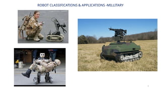
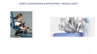
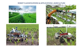
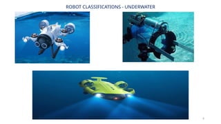
Different Applications of Robots
10
UNIT 1 FUNDAMENTALSOF
ROBOT ROBOT
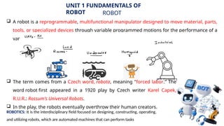
A robot is a reprogrammable, multifunctional manipulator designed to move material, parts,
tools, or specialized devices through variable programmed motions for the performance of a
variety of tasks.
The term comes from a Czech word, robota, meaning "forced labor." The
word robot first appeared in a 1920 play by Czech writer Karel Capek,
R.U.R.: Rossum's Universal Robots.
In the play, the robots eventually overthrow their human creators.
ROBOTICS: It is the interdisciplinary field focused on designing, constructing, operating,
and utilizing robots, which are automated machines that can perform tasks
11.
11
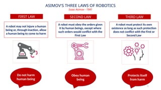
ASIMOV'S THREE LAWSOF ROBOTICS
Isaac Asimov - 1941
FIRST LAW
A robot may not injure a human
being or, through inaction, allow
a human being to come to harm
A robot must obey the orders given
it by human beings, except where
such orders would conflict with the
First Law
SECOND LAW
A robot must protect its own
existence as long as such protection
does not conflict with the First or
Second Law
THIRD LAW
Do not harm
human being
Obey human
being
Protects itself
from harm
12.
12
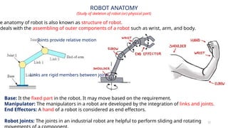
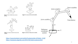
ROBOT ANATOMY
(Study ofskeleton of robot (or) physical part)
Base: It the fixed part in the robot. It may move based on the requirement.
Manipulator: The manipulators in a robot are developed by the integration of links and joints.
End Effectors: A hand of a robot is considered as end effectors.
Robot Joints: The joints in an industrial robot are helpful to perform sliding and rotating
e anatomy of robot is also known as structure of robot.
deals with the assembling of outer components of a robot such as wrist, arm, and body.
Links are rigid members between joints
Joints provide relative motion
13.
13
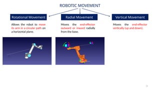
ROBOTIC MOVEMENT
Rotational MovementRadial Movement Vertical Movement
Allows the robot to move
its arm in a circular path on
a horizontal plane.
Moves the end-effector
outward or inward radially
from the base.
Moves the end-effector
vertically (up and down).
14.
14
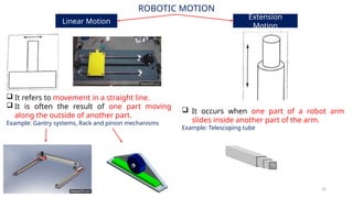
ROBOTIC MOTION
Linear Motion
Extension
Motion
It refers to movement in a straight line.
It is often the result of one part moving
along the outside of another part.
Example: Gantry systems, Rack and pinion mechanisms
It occurs when one part of a robot arm
slides inside another part of the arm.
Example: Telescoping tube
15.
15
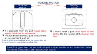
ROBOTIC MOTION
Rotation
Motion
Twisting
Motion
Itis produced when one part moves about
a point that is not its own centre.
This can be seen when a part turns around
an external point, such as:
The arm bending at the elbow, where the motion does not
occur at the arm’s center but at the elbow joint.
It occurs when a part turns about its own
centre, like the rotation of the human neck
joint.
These four types form the foundational motion types in robotics and automation, often
referred to collectively as LERT classification system.
16.
16
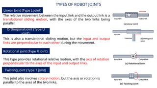
TYPES OF ROBOTJOINTS
Linear Joint (Type L joint)
Orthogonal joint (Type U
joint)
The relative movement between the input link and the output link is a
translational sliding motion, with the axes of the two links being
parallel.
This is also a translational sliding motion, but the input and output
links are perpendicular to each other during the movement.
Rotational joint (Type R joint)
This type provides rotational relative motion, with the axis of rotation
perpendicular to the axes of the input and output links.
Twisting joint (Type T joint)
This joint also involves rotary motion, but the axis or rotation is
parallel to the axes of the two links.
17.
TYPES OF ROBOTJOINTS
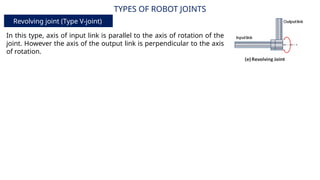
Revolving joint (Type V-joint)
In this type, axis of input link is parallel to the axis of rotation of the
joint. However the axis of the output link is perpendicular to the axis
of rotation.
18.
18
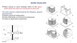
WORK ENVELOPE
Workvolume or work envelope refers to the space
within which the robot can manipulate its wrist end.
The work volume is determined by the following physical
characteristics:
Robot’s physical configuration.
Sizes of the body, arm and wrist components.
Limits of robot’s joint movements.
19.
FOUR COMMON ROBOTCONFIGURATIONS (OR) ROBOT
GEOMETRY
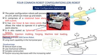
Polar Configuration (Spherical)
The polar configuration robots will possess
an arm, which can move up and down.
It comprises of a rotational base along
with a pivot.
It has one linear & two rotary joints that
allows the robot to operate in a spherical
work volume.
It is also stated as Spherical Coordinate
Robots.
Example: Unimate 2000 Series Robot.
Advantage
Long reach capability in the horizontal position.
Disadvantage
Vertical reach is low.
Low mechanical stiffness
Complex construction
Position accuracy decreases with the increasing radial
Applications: Injection molding, Forging, Machine tool loading,
Material transfer.
20.
FOUR COMMON ROBOTCONFIGURATIONS (OR) ROBOT
GEOMETRY
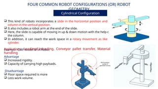
Cylindrical Configuration
Advantage
Increased rigidity.
Capacity of carrying high payloads.
Disadvantage
Floor space required is more
Less work volume.
This kind of robots incorporates a slide in the horizontal position and a
column in the vertical position.
It also includes a robot arm at the end of the slide.
Here, the slide is capable of moving in up & down motion with the help of
the column.
In addition, it can reach the work space in a rotary movement as like a
cylinder.
Example: GMF Model M1A Robot
Applications: Loading/Unloading, Conveyor pallet transfer, Material
handling
21.
FOUR COMMON ROBOTCONFIGURATIONS (OR) ROBOT
GEOMETRY
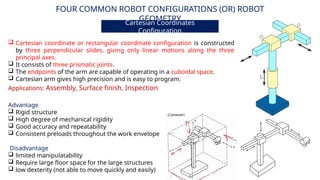
Cartesian Coordinates
Configuration
Advantage
Rigid structure
High degree of mechanical rigidity
Good accuracy and repeatability
Consistent preloads throughout the work envelope
Disadvantage
limited manipulatability
Require large floor space for the large structures
low dexterity (not able to move quickly and easily)
Applications: Assembly, Surface finish, Inspection
Cartesian coordinate or rectangular coordinate configuration is constructed
by three perpendicular slides, giving only linear motions along the three
principal axes.
It consists of three prismatic joints.
The endpoints of the arm are capable of operating in a cuboidal space.
Cartesian arm gives high precision and is easy to program.
22.
FOUR COMMON ROBOTCONFIGURATIONS (OR) ROBOT
GEOMETRY
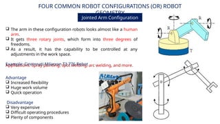
Jointed Arm Configuration
Advantage
Increased flexibility
Huge work volume
Quick operation
Disadvantage
Very expensive
Difficult operating procedures
Plenty of components
Applications: Spray painting, spot welding, arc welding, and more.
The arm in these configuration robots looks almost like a human
arm.
It gets three rotary joints, which form into three degrees of
freedoms.
As a result, it has the capability to be controlled at any
adjustments in the work space.
Example: Cincinnati Milacron T3 776 Robot
23.
23
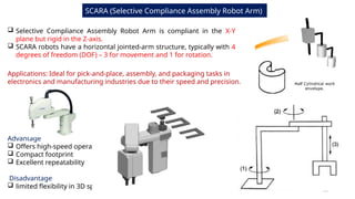
SCARA (Selective ComplianceAssembly Robot Arm)
Selective Compliance Assembly Robot Arm is compliant in the X-Y
plane but rigid in the Z-axis.
SCARA robots have a horizontal jointed-arm structure, typically with 4
degrees of freedom (DOF) – 3 for movement and 1 for rotation.
Applications: Ideal for pick-and-place, assembly, and packaging tasks in
electronics and manufacturing industries due to their speed and precision.
Advantage
Offers high-speed operation
Compact footprint
Excellent repeatability
Disadvantage
limited flexibility in 3D space
24.
24
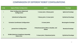
COMPARASION OF DIFFERENTROBOT CONFIGURATIONS
S. No Types of Robot Configuration Joints Envelope
1
Polar Configuration (Spherical)
Configuration
1 Linear Joint, 2 Rotary Joint Spherical Envelope
2 Cylindrical Configuration 1 Rotary Joint, 2 Linear Joint Cylindrical Envelope
3 Cartesian Coordinates Configuration 3 Linear Joints Rectangular Envelope
4 Jointed Arm Configuration
3 Rotational Joints (Wrist, shoulder, and
elbow)
Revolute Envelope
5 SCARA (Selective Compliance Assembly
Robot Arm)
1 Linear Joint, 2 Rotational Joints Cylindrical Envelope
25.
25
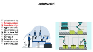
AUTOMATION
Definition ofRobot
Robot Anatomy
Coordinate Systems, Work Envelope
Types and Classification of Robots
Specifications of Robots
Pitch, Yaw, Roll, Joint Notations
Speed of Motion
Pay Load
Robot Parts and their Functions
Need for Robots
Different Applications of Robots