This document provides information about tacheometry, which is a method of surveying that determines horizontal and vertical distances from instrumental observations. It discusses how tacheometry can be used when obstacles make traditional surveying difficult. The key aspects covered include:
- Defining tacheometry and the measurements it provides
- When tacheometry is advantageous over other surveying methods
- The instruments used, including tacheometers and levelling rods
- How horizontal and vertical distances are calculated using constants
- The different types of tacheometer diaphragms and telescopes
- The fixed hair method for taking readings
The document discusses different types of traverses and methods for conducting traverse surveys. It describes two types of traverses: open traverses that begin and end at points of known and unknown positions, and closed traverses that begin and end at points of known positions, including closed-loop traverses that begin and end at the same point. It also outlines four methods for determining directions during traversing: chain angle method, free needle method, fast needle method, and measuring angles between lines. Finally, it discusses instruments used for measuring angles like compasses and theodolites, and defines different types of bearings including true, magnetic, and arbitrary bearings.
Tacheometric surveying uses a tacheometer to determine horizontal and vertical distances through angular measurements. A tacheometer is a theodolite fitted with stadia hairs and an anallatic lens. The tacheometric formula relates the staff intercept, focal length, stadia interval and additive constant to calculate horizontal distances. Methods include stadia, fixed/movable hair, and non-stadia techniques. Determining the tacheometer constant involves measuring distances and staff intervals at stations to solve equations. Errors arise from incorrect stadia intervals or graduations. Tacheometric surveying provides distances in rough terrain but with less precision than other methods.
This document describes different methods of trigonometric leveling to determine the elevation of points. Trigonometric leveling uses vertical angles measured with a theodolite and distances to calculate elevations. There are methods to determine elevations when the base is accessible and inaccessible, and when instrument stations and objects are in the same or different vertical planes. Calculations use trigonometric functions and relationships between angles and distances in triangles formed by the instrument stations and object.
Tacheometric surveying is a method of rapidly determining horizontal and vertical positions of points using optical measurements rather than traditional tape or chain measurements. A tacheometer, which is a transit theodolite fitted with a stadia diaphragm, is used to measure the horizontal and vertical angles to a stadia rod or staff held at survey points. Formulas involving the stadia interval, staff intercept readings, and calculated constants are used to determine horizontal distances and elevations from the instrument to points. Measurements can be taken with horizontal lines of sight or inclined lines of sight when the staff is held vertically or normal to the line of sight.
Tacheometry is a surveying method that uses optical instruments like a theodolite fitted with a stadia diaphragm to measure horizontal and vertical distances between points. It works on the principle that the ratio of distance from the instrument to the base of an isosceles triangle and the length of the base is constant. Distances are calculated using stadia intercept readings and multiplying constants based on the focal length of the instrument's objective lens. Tacheometry offers faster measurement compared to traditional chaining and is useful for surveys in difficult terrain like rivers, valleys, or undulating ground where conventional surveying would be inaccurate or slow.
The document provides information on calculating area and volume for engineering projects. It discusses several methods for calculating the area of regular and irregular shapes, including using mathematical equations, coordinates, planimeters, trapezoidal rule, mid-ordinate rule, and Simpson's rule. It also outlines various approaches to calculating volumes based on cross-sections, spot levels, and contour lines, including end area method, mean area method, and prismoidal formula. Examples are provided to demonstrate calculating area and volume using these different techniques.
The document provides information about theodolites. It begins with an introduction stating that a theodolite is used to measure horizontal and vertical angles more precisely than a magnetic compass. It then discusses the main parts of a theodolite including the horizontal circle, vertical circle, telescope, and levels. The document also covers the history of theodolites from their early origins to modern electronic versions. It describes how to operate a transit vernier theodolite including terms like centering, transiting, swinging the telescope, and changing face. Finally, it discusses the permanent and temporary adjustments needed to ensure accurate theodolite measurements.
1) Levelling is the process of determining the relative elevations of points on or near the earth's surface. It is important for engineering projects to determine elevations along alignments.
2) Levelling is used to prepare contour maps, determine altitudes, and create longitudinal and cross sections needed for projects.
3) Key terms include bench mark, datum, reduced level, line of collimation, and height of instrument. Different types of levelling include simple, differential, fly, longitudinal, and cross-sectional levelling.
1) Curves are gradual bends provided in transportation infrastructure like roads, railways and canals to allow for a smooth change in direction or grade.
2) There are two main types of curves - horizontal curves which provide a gradual change in direction, and vertical curves which provide a gradual change in grade.
3) Curves are needed to safely guide vehicles and traffic when changing directions or grades, to improve visibility, and to prevent erosion of canal banks from water pressure.
Curves are used in transportation routes to gradually change direction between straight segments. There are several types of curves including simple, compound, reverse, and transition curves. A simple circular curve connects two tangents with a single arc, and is defined by its radius or degree. Transition curves provide a gradual transition between tangents and circular curves to avoid abrupt changes in grade or superelevation that could cause vehicles to overturn. There are several methods for laying out circular curves, including using offset distances from the long chord between tangent points or measuring deflection angles from the initial tangent.
This document discusses the topic of chain surveying for a civil engineering class project. It provides definitions of chain surveying, noting that it involves measuring linear distances between survey stations to divide an area into triangles without taking angular measurements. It then outlines the key principles and terms of chain surveying, such as defining main stations, subsidiary stations, tie stations, main survey lines, base lines, check lines, and tie lines. Finally, it provides the basic procedures for conducting a chain survey between two stations.
Tacheometric surveying is a method of surveying that determines horizontal and vertical distances optically rather than through direct measurement with a tape or chain. It uses an instrument called a tacheometer fitted with a stadia diaphragm to rapidly measure distances. The key principles are that the ratio of perpendicular to base is constant in similar triangles, allowing horizontal distance and elevation to be calculated from observed angles and staff intercept readings. Common tacheometric systems include fixed hair stadia, subtense stadia, and tangential methods. Distance and elevation formulas are derived for horizontal, inclined, and depressed line of sights depending on staff orientation. Tacheometric surveying is well-suited for difficult terrain where direct measurement is challenging
This document discusses control surveying and triangulation. It notes that control surveying must account for the curvature of the Earth and refraction, as lines of sight are not entirely straight. It distinguishes between plane and geodetic surveying, with the latter accounting for the spherical shape of the Earth. The document then discusses establishing control points through triangulation, including different classes of triangulation, steps in triangulation like selecting stations, and erecting signals and towers.
1. Levelling is used to determine relative heights and elevations of points and establish points at required elevations. It involves using instruments like levels and staffs.
2. There are different types of levels (dumpy, tilting, wye, automatic) and staffs (self-reading, target). Precise levelling is done to establish permanent benchmarks.
3. Adjustments must be made to level instruments during setup and permanently. Methods like differential, profile and cross levelling are used depending on the task. Reciprocal levelling involves backsight-foresight exchange to check for errors.
This document discusses contouring and contour maps. It defines a contour line as a line connecting points of equal elevation. The vertical distance between consecutive contours is called the contour interval, which depends on factors like the nature of the ground and the map scale. Contour maps show the topography of an area and can be used for engineering projects, route selection, and estimating earthworks. Methods of plotting contours include direct methods using levels or hand levels, and indirect methods like gridding, cross-sectioning, and radial lines. Characteristics of contours provide information about the landscape.
This document provides instructions for using a digital theodolite to take horizontal and vertical angle measurements of reference points by following several steps:
1) Setting up the tripod and centering the theodolite over a reference mark.
2) Leveling the theodolite using circular and plate levels to precisely align it.
3) Taking multiple rounds of horizontal and vertical angle measurements in both face-left and face-right positions to reference points, and calculating the mean values.
4) Packing up the theodolite by reversing the setup steps.
Theodolite traversing, purpose and principles of theodolite traversingDolat Ram
The document discusses theodolite traversing, which is a surveying method that uses a theodolite to measure angles and a chain or tape to measure distances between control points called traverse stations.
The theodolite is used to measure horizontal and vertical angles, and there are two main types - optical and electronic digital theodolites. The chain or tape is used to measure distances between traverse stations.
A traverse consists of straight lines connecting traverse stations, with known lengths and angles defined by theodolite measurements. Traverses can be open or closed loops. Theodolite traversing is used for area computation, surveying, data reduction, and indirect measurement of elevations, distances, and
Lec. 11 setting out simple circular curveAhmed Qasim
1. The document discusses three methods for setting out a simple circular curve in engineering and surveying projects: the tangential angle method, the tangent offset method, and the chord offset method.
2. The tangential angle method uses a theodolite to measure deflection angles and chords to lay out points along the curve.
3. The tangent offset method uses only a chain and tape, measuring offsets perpendicular to tangents to locate points for small curves where high accuracy is not required.
4. Similarly, the chord offset method divides a chord between the PC and PT into segments and measures offsets perpendicular to locate points along the curve.
This document discusses the use of a theodolite for surveying. It begins by explaining that a theodolite is needed to precisely measure horizontal and vertical angles, unlike a compass. It then defines theodolite surveying as surveying that measures angles using a theodolite. The document goes on to classify theodolites based on their horizontal axis and method of angle measurement. It describes the basic parts of a transit vernier theodolite and explains terms used in manipulating one. Finally, it discusses methods for measuring horizontal angles, including the general, repetition, and reiteration methods.
1. Contours are imaginary lines on a map that connect points of equal elevation. Contour maps show these lines, representing the topography of the land.
2. There are two main methods for creating contour maps - direct and indirect. The direct method involves precisely surveying points along contour lines in the field. The indirect method takes spot elevations across an area and interpolates the contour lines.
3. Common techniques for indirect contouring include dividing the area into squares and taking elevation readings at each corner, taking cross-sections of long strips, and using a tacheometer which can measure horizontal distances and elevations from a single station.
This document discusses triangulation, which is a surveying technique used to establish horizontal control networks over large areas. It involves measuring angles and lengths within networks of triangles. There are different orders of triangulation based on accuracy and area covered, including primary, secondary, and tertiary triangulation. Key aspects discussed include triangulation station layout and design, angle and distance measurements, controlling errors, and computation of unknown lengths and directions within triangles.
Introduction, purpose, principle, instruments, methods of tacheometry, stadia constants, anallatic lens, Subtense bar, field work in tacheometry, reduction of readings, errors and precisions.
surveying Engineering
Fly Levelling
Fly leveling: -Fly leveling is just like differential leveling carried
out to check the accuracy of leveling work. It is a very approximate
form of leveling in which sights are taken as large as possible. in this
method, a line of levels is run to determine approximately reduced
levels of the points carried out with more rapidly and less precision
The aim of fly Levelling: The main purpose of this type of leveling is
to check the values of the reduced levels of the bench marks already
fixed. In this method only back sight and foresight are taken. There is no need of intermediate sights. However great care has to be taken for selecting the change points (Turning Points) and for taking reading on the change points because the accuracy of leveling depends upon these
-Create Bench Marks (BM).
Bench Marks
Bench Mark is a point of known elevation, there are three Type of Bench Marks
1-Perment Bench Mark.
2-Orbitrary Bench Mark .
3-Temporary Bench Mark .
-Leveling Process Calculation.
1. Height of collimation method
2. Rise and Fall method
How do we find horizontal distance using levelling Machine.
Fly Levelling Close loop survey.
Fly and Differential leveling Using (Rise & fall) and (HI)methods.
*Checks for Errors
-Misclosure
Allowable closing error
Where:
D =Distance in km
E = Misclosure error in (mm).
C = 30 for fixed levelling process in rough ground.
C = 15 for normal leveling in flat area (Good work)
Fly Levelling example
Computation of Elevations for an open loop survey H.I method
Computation of Elevations
Differential Leveling
Computation of Elevations
-Correction For Errors in Leveling
1. Errors Due to the line of sight being not horizontal
2. Error Due to Curvature and refraction.
Errors in differential leveling: -
1) Non adjustment of the instrument: -
a) Adjustment of cross-wire ring
b) Adjustment of the bubble tube
c) Adjustment of line of sight
2-Errors in levelling
• Collimation line
• Parallax
• Change point instability
• Instrument instability
• Benchmark instability
• Staff reading errors , • Staff verticality • Level Instrument shading • Temperature on staff • Booking errors) • Earth curvature • Refraction • The Bubble not center.
3-Constant error (instrumental error):
A. Non vertically of the staff.
B. Collimation error in the instrument.
C. Staff gradation error.
4- Random error (natural error):
A. Effect of wind and temperature.
B. Soft and hard ground.
C. Change points. CP
D. Human deficiencies and neglect
Prepared by:
Asst. Prof. Salar K.Hussein
Mr. Kamal Y.Abdullah
Asst.Lecturer. Dilveen H. Omar
Erbil Polytechnic University
Technical Engineering College
Civil Engineering Department
EDM-Electronic Distance Measurement by Denis Jangeed.pptxDenish Jangid
EDM-Electronic Distance Measurement by Denis Jangeed
Origin of Electronic Distance Measurement
Principle of E.D.M. (Electronic Distance Measurements), Modulation,
Types of E.D.M., Distomat,
advantages and application.
electromagnetic waves
EDM Range 100 KM
EDM accuracy of 1 in 105
Electromagnetic Spectrum Range
microwaves, infrared waves and visible light waves
Measurement of distance with EDM and a Reflector
Classification of Electronic Distance Measurement Instrument
EDM instruments are classified based on the type of carrier wave as
Microwave instruments
Infrared wave instruments
Light wave instruments.
Parts of EDM instruments
Geodimeter
Tellurometer
Distomat
Errors in EDM
A total station is an instrument that can measure both horizontal and vertical angles as well as slope distances. It combines an electronic theodolite with a distance measurement component. Total stations use electromagnetic waves or pulses to measure distances to a reflector or target. They can measure distances to a few kilometers with an accuracy of 2-3 mm at short ranges, decreasing to 4-5 mm at 1 km. Total stations are commonly used in surveying, civil engineering, and construction to define positions through combined angle and distance measurements.
A total station is an electronic/optical instrument used in modern surveying that combines an electromagnetic distance measuring instrument, electronic theodolite, and microprocessor to measure horizontal and vertical angles as well as sloping distances. It has a memory card to store data and battery that provides power for 3 to 8 hours. Total stations can perform functions like averaging measurements, correcting distances, calculating point elevations and coordinates, and have angular accuracy ranging from 1 to 20 seconds and distance accuracy of +/- 10mm to 2mm. They are used for applications like remote elevation measurement, fixing missing pillars, resection, area calculation, and more.
A total station is an electronic/optical instrument that combines an electronic distance meter, electronic theodolite, and microprocessor. It can measure horizontal and vertical angles as well as sloping distances to objects. It has high accuracy, ranging from 1-20 seconds for angles and +/- 2-10mm for distances. Total stations are used for surveying applications like remote elevation measurement, fixing missing pillars, resection, area calculation, and more. They provide advantages like great accuracy, quick setup and data collection, and on-board results display.
Distance measurement is a basic component of surveying. There are two main types of distance measurement: direct and indirect. Direct measurement uses instruments like tapes to directly measure distances. Indirect measurement determines distances through computations based on direct measurements of related quantities, like angles and line lengths. Modern electronic distance measurement (EDM) uses electromagnetic waves and the speed of light to indirectly measure distances electronically between two points with high accuracy and efficiency. Total stations integrate EDM and angle measurement capabilities into a single precise digital instrument.
This document discusses modern surveying instruments such as total stations and digital levels. It explains that total stations can measure horizontal and vertical angles as well as slope distances electronically using electromagnetic waves. Total stations have replaced traditional surveying equipment and come in manual, semi-automatic, and automatic varieties. Digital levels also use electronic image processing to read staffs automatically and provide elevation measurements and levelling capabilities. Modern surveying instruments have improved accuracy and efficiency over traditional equipment through incorporation of electronic components and digital technologies.
1. The document discusses electronic distance measurement (EDM) using a total station to measure distances between two points. An EDM emits a beam of light to a target prism and back to calculate the distance based on the phase shift of the returning beam.
2. Equipment used includes a total station, tripod, and reflector. The procedure involves setting up the total station on point A and placing the reflector on point B to take distance measurements.
3. Multiple readings were taken between two points over 100 meters apart by different people. Taking the sum of readings and dividing by the number of readings yielded a result of 112.4481 meters, demonstrating EDM's high accuracy for distance measurement.
Modern surveying instruments have advanced significantly with technology. Traditional instruments like tapes, theodolites, compasses and plane tables have been replaced by electromagnetic distance measurement (EDM) devices, total stations, global navigation satellite systems (GNSS), and unmanned aerial vehicles (UAVs). These modern instruments allow for faster, simpler and more accurate distance, angle, and coordinate measurement compared to conventional methods. Sources of error from instruments are also reduced. Total stations integrate EDM and theodolite capabilities to directly measure horizontal and slope distances as well as angles to compute point coordinates. GNSS uses satellite signals for real-time three dimensional coordinate determination. UAVs capture aerial images that can be used to generate high
This document provides an overview of electronic distance measuring (EDM) devices and total stations used for surveying. It discusses the history and evolution of surveying techniques from manual methods to modern EDMs and total stations. Key points covered include:
- How total stations integrate an electronic theodolite and EDM to measure angles and distances, then use trigonometry to calculate coordinates.
- Features of Pentax total stations like automatic environmental sensing, auto focusing, and narrow visible beams that improve accuracy and efficiency.
- Software tools like Power Topolite, PSF, and Pythagoras that support data collection, calculations, stakeout, and CAD functions on Pentax total stations.
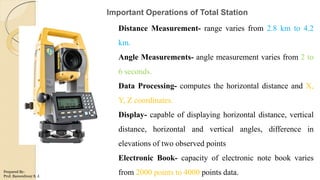
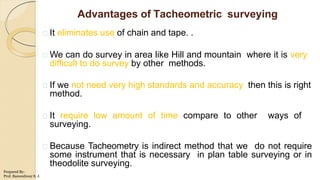
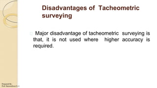
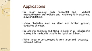
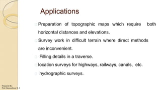
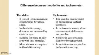
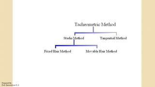
The document discusses tacheometric surveying, which is a method of angular surveying that determines horizontal and vertical distances from instrumental observations alone, eliminating chaining operations. It is well-suited for hilly, broken, or inaccessible areas. The key principles are described, including the use of a tacheometer instrument fitted with stadia wires, and a stadia rod. The two main methods - fixed hair and movable hair - are outlined. Errors and precautions for tacheometric surveying are also provided.
This document contains a report from a group of civil engineering students at the University of Malaysia Pahang on a theodolite traversing exercise. The group conducted a traverse survey within the university campus to establish control networks and locate survey stations. They measured bearing and length between stations using a total station. Their report includes an introduction, objectives, equipment used, procedures, field book, scaled drawing of the survey, and analysis. The traverse was completed within specifications for angular and linear closure errors.
This document discusses advances in metrology, specifically laser metrology and interferometry. It begins by explaining the principles and components of lasers and how they are used for precision measurement. Examples of laser measuring machines described include laser telemetric systems, laser and LED distance measuring instruments, scanning laser gauges, and laser interferometers. Interferometry uses laser beams to perform highly accurate linear and angular measurements. Coordinate measuring machines and digital devices for computer-aided inspection are also summarized.
Surveying involves measuring horizontal and vertical distances between objects and angles between lines to determine the relative spatial locations of points on Earth. Key aspects of surveying include determining distances, angles, directions, elevations and volumes from survey data. Survey data is presented graphically in maps, profiles and diagrams. Modern surveying utilizes electronic distance measuring devices, theodolites to measure angles, and coordinate systems to provide addresses for points on Earth's surface.
This document discusses electronic distance measurement (EDM) in surveying. It lists the group members of Hope Enterprise University College surveying assignment and describes different types of EDM instruments, including total stations, laser distance meters, and radar distance meters. It also discusses sources of temperature variation error in EDM measurements, such as thermal gradient error, sensor nonlinearity, and hysteresis.
The document discusses advances in metrology, including laser interferometry and coordinate measuring machines (CMMs). It describes the principles and components of laser interferometry, including laser sources, optical elements, and measurement receivers. Coordinate measuring machines are discussed, including their construction, types of probes, accuracy considerations, and applications for precision inspection. Computer-aided inspection using machine vision systems is also summarized, outlining the key stages of image generation, processing, and analysis.
Units and measurements chapter 1 convertedAbhirajAshokPV
Class 11 Physics chapter one notes. simplified and reduced for better understanding and quick revisions.
Notes on Units, physical Quantities, errors, calculation of errors, and dimension analysis.
TOTAL STATION: THEORY, USES AND APPLICATIONS. Ahmed Nassar
TOTAL STATION: THEORY, USES AND APPLICATIONS.
The total station, (also known as electronic tacheometer) is an instrument that can measure horizontal and vertical angles together with slope distance and can be considered as combined EDM plus electronic theodolite. In common with other electronic surveying equipment, total stations are operated using a multi-function keyboard which is connected to a microprocessor built into the instrument. The microprocessor not only controls both the angle and distance measuring systems but is also used as a small computer that can calculate slope corrections, vertical components, rectangular coordinates and, in some cases, can also store observations directly using an internal memory. Nowadays surveying systems are available which can be use in an integrated manner with Global Positioning System (GPS). so, future total stations may have integrated GPS receivers as part of the measurement unit.
Dock and Harbor Engineering: Inland Water Transport in India, Tides, Winds and Waves Erosion, Transport of Sediments, Beach Drift, Littoral Drift, Sand Bars, Coast Protection, Classification of Ports and Harbors, Site Selection, Features of Break Waters, Jetties, Wharves, Piers, Facilities required, Dry Docks, Wet Docks, Lift Docks. Floating Docks, Spillways, Navigational Aids, Lighthouses, Terminal Buildings, and Dredging- Special Equipment.
Course Outcomes-
CO1- Comprehend various types of transportation systems and their history of the development
CO2- Comprehend various types of pavements
CO3- Design the pavements by considering various aspects associated with traffic safety measures.
Topic Learning Outcomes:
C603.1.1 Understand the significance of various modes of transportation
C603.1.2 Discuss developments in road construction and Classify roads based on certain criteria.
C603.1.3 Describe factors for selecting road alignments and carrying out road surveys.
C603.2.1 Impart knowledge about various materials used for highway construction.
C603.2.2 Describe tests carried out on materials used for highway construction.
C603.2.3 Introduce the fundamental concepts of highway construction
C603.2.4 Classify pavements on the basis of structural behavior.
C603.3.1 Design different road geometrical elements.
C603.3.2 Identify traffic stream characteristics and Design a pre-timed signalized intersection.
C603.3.3 Identify causes of road accidents and measures for road safety.
C603.3.3 Analyze the important features of pavement designing.
This document outlines the design of flexible pavements using IRC: 37-2012. It discusses the scope, design criteria, design traffic considerations including vehicle damage factors and distribution, and provides pavement thickness design charts. It also describes the composition of flexible pavements including materials for the sub-base, base and bituminous surfacing layers. Two numerical examples of designing flexible pavements for given traffic and soil conditions are included using the IRC method.
Module 4: Traffic Engineering
(8 Lectures)
Traffic Characteristics, Speed, Journey Time and Delays, Vehicle Volume Counts, Origin and Destination Studies, Analysis and Interpretation of Survey Data, Traffic Operations, Design of Signals and Rotary intersections, Parking Space Design,Highway Lighting, Planning and Administration, Road Markings, Signs
Road Accidents and Safety:Classification, Causes, Mitigation and Control Measures, Aspects of Safety in Usage of Roads, Type and Design of anti-crash barriers, Introduction to Intelligent Transport Systems (ITS).
Module 1: Introduction
(6 Lectures)
•Importance of various modes of transportation,
•Highway Engineering,
•Road Classification,
•Developments in Road Construction,
•Highway Planning,
•Alignment and Surveys
Geology of Dams, Reservoirs, Tunnels and Bridges, Dam, types of dams, Influence of geological conditions on location, alignment, design and types of a dam, geological considerations in site selection for dams, Site improvement techniques, dams on carbonate rocks, sedimentary rocks, folded strata and Deccan traps, favorable and unfavorable geological conditions for a reservoir site. Tunneling:- Types of tunnels, the influence of geological conditions on tunneling, difficulties during tunneling, tunnel lining, tunneling in folded strata, sedimentary rocks and Deccan traps. Bridges:- Types of bridges, dependence of types of bridges on geological conditions.
Structural geology is the study of rock structures and their deformation histories. The goal is to understand the stress fields that caused the observed strain and geometries in rocks. Structural features like faults and folds are important in fields like economic geology because they can form traps that concentrate resources like petroleum and metals. Geologists study these features by measuring the orientations and relationships of rock structures at outcrops.
Scope of Engg. Geology and Civil Engineering Applications. Geology in Construction Jobs, Geology & Civil Engineering, Geology in Water Resource Development, Brief History of Formation of Earth and Earth Crust, Formation of different rocks,
Minerals are natural inorganic substances that make up rocks. They form through natural geological processes within the earth's crust and do not come from living things. Minerals can be identified based on their physical properties such as hardness, color, streak, luster, and cleavage or fracture pattern. Igneous rocks form as magma or lava cools and solidifies. Sedimentary rocks form through the compaction and cementation of sediments. Metamorphic rocks form from the alteration of existing rock types subjected to heat and pressure in metamorphism.
Absorption of sound, various materials, Sabine’ s formula, optimum reverberation time, conditions for good acoustics
Sound insulation: Acceptable noise levels, noise prevention at its source, transmission of noise, Noise control-general
considerations
This document discusses traditional building materials like stone, brick, timber, bamboo, mud, and lime. It then discusses low-cost housing materials and methods, focusing on using low-cost materials and efficient construction techniques. Specific low-cost materials mentioned include hollow concrete blocks, filler slabs for ceilings, prefabricated structural elements, and doors and windows. The document emphasizes selecting materials based on cost, energy efficiency, durability, and other factors. It also briefly discusses maintenance, repairs, and rehabilitation of housing.
This presentation helps you to get the conceptual idea about Bridge Superstructures as per the Syllabus of DBATU, Last Year BTech Lonere.
4.1 Bridge Engineering: Super-structures
4.2 Simple bridges or beam bridges: Deck bridges, Through bridges, Semi-through bridges
4.3 Introduction, advantages and disadvantages: Continuous bridges, Cantilever bridges, Arch bridges, Bow-string girder type bridges, Rigid frame bridges, Portal frame bridges, Suspension bridges, Cable-stayed bridges, Composite bridges
4.4 Materials for super-structures: Cement concrete, Masonry, Steel, Timber etc.
This presentation helps you to get the detailed basics as per DBATU, Lonere for Last Year Civil BTech for subject Infrastructure Engg.
Module-3 Bridge Engineering: Sub-structures, Determination of design discharge, Linear Water Way, Economical Span, Afflux, Scour depth, Indian Road Congress Bridge Code
Abutments: Definition, Functions, Dimensions, Types, Forces acting on an abutment,Conditions of stabilityPiers: Definition, Function, Types, Forces acting on a pier, Conditions of stability, Dimensions, Location, Abutment pier
Wing walls: Definition, Functions, Types, Forces acting on a wing wall, Conditions of stability, Dimensions, Precautions
Materials for sub-structures: Cement concrete, Masonry, Steel etc.
This presentation helps you to understand all concepts as per DBATU, Lonere for Last Year BTech Civil Subject- Infrastructural Engg.
Module-II
Points and Crossings:
Standard types, Design of simple turnout, various types of Junctions, Stations and Yards: Purpose, Location, Site selection, general layouts of Terminus and Junction, Signaling and Interlocking, Construction and Maintenance of Track, Modern trends in Railways
etc.
This presentation provides you the conceptual knowledge as per DBATU, Lonere Last Year BTech Civil subject, Infrastructure Engg. Module-V Tunnel Engineering
Shape and Size of Tunnel Shafts, Pilot Tunnels, Tunneling in Hard Rock, Tunneling in Soft Materials, Drilling-Patterns, Blasting, Timbering, Mucking, Tunnel Lining, Advances In Tunneling Methods, Safety Measures, Ventilation, Lighting and Drainage of Tunnels
etc.
This presentation will help you to interact with all the academic key points for the Subject B T C V C 7 0 2 I n f r a s t r u c t u r e E n g i n e e r i n g, Proposed Course Contents for B. Tech. in Civil Engineering w.e.f. June 2020.
Module 1 (5 Lectures)
Railway Engineering: Permanent Way, gauges, rails, sleepers, ballast, sub grade formation, fixtures and fastenings,
Geometric Design of tracks- Horizontal Alignment, Vertical Alignment Etc.
Building planning byelaws & regulations as per SP-7, National Building Code of India group 1 to 5, planning of residential building: bungalows, row bungalows, apartments and twin bungalows, procedure of building permission, significance of commencement, plinth completion or occupancy certificate.
TIME DIVISION MULTIPLEXING TECHNIQUE FOR COMMUNICATION SYSTEMHODECEDSIET
Time Division Multiplexing (TDM) is a method of transmitting multiple signals over a single communication channel by dividing the signal into many segments, each having a very short duration of time. These time slots are then allocated to different data streams, allowing multiple signals to share the same transmission medium efficiently. TDM is widely used in telecommunications and data communication systems.
### How TDM Works
1. **Time Slots Allocation**: The core principle of TDM is to assign distinct time slots to each signal. During each time slot, the respective signal is transmitted, and then the process repeats cyclically. For example, if there are four signals to be transmitted, the TDM cycle will divide time into four slots, each assigned to one signal.
2. **Synchronization**: Synchronization is crucial in TDM systems to ensure that the signals are correctly aligned with their respective time slots. Both the transmitter and receiver must be synchronized to avoid any overlap or loss of data. This synchronization is typically maintained by a clock signal that ensures time slots are accurately aligned.
3. **Frame Structure**: TDM data is organized into frames, where each frame consists of a set of time slots. Each frame is repeated at regular intervals, ensuring continuous transmission of data streams. The frame structure helps in managing the data streams and maintaining the synchronization between the transmitter and receiver.
4. **Multiplexer and Demultiplexer**: At the transmitting end, a multiplexer combines multiple input signals into a single composite signal by assigning each signal to a specific time slot. At the receiving end, a demultiplexer separates the composite signal back into individual signals based on their respective time slots.
### Types of TDM
1. **Synchronous TDM**: In synchronous TDM, time slots are pre-assigned to each signal, regardless of whether the signal has data to transmit or not. This can lead to inefficiencies if some time slots remain empty due to the absence of data.
2. **Asynchronous TDM (or Statistical TDM)**: Asynchronous TDM addresses the inefficiencies of synchronous TDM by allocating time slots dynamically based on the presence of data. Time slots are assigned only when there is data to transmit, which optimizes the use of the communication channel.
### Applications of TDM
- **Telecommunications**: TDM is extensively used in telecommunication systems, such as in T1 and E1 lines, where multiple telephone calls are transmitted over a single line by assigning each call to a specific time slot.
- **Digital Audio and Video Broadcasting**: TDM is used in broadcasting systems to transmit multiple audio or video streams over a single channel, ensuring efficient use of bandwidth.
- **Computer Networks**: TDM is used in network protocols and systems to manage the transmission of data from multiple sources over a single network medium.
### Advantages of TDM
- **Efficient Use of Bandwidth**: TDM all
International Conference on NLP, Artificial Intelligence, Machine Learning an...gerogepatton
International Conference on NLP, Artificial Intelligence, Machine Learning and Applications (NLAIM 2024) offers a premier global platform for exchanging insights and findings in the theory, methodology, and applications of NLP, Artificial Intelligence, Machine Learning, and their applications. The conference seeks substantial contributions across all key domains of NLP, Artificial Intelligence, Machine Learning, and their practical applications, aiming to foster both theoretical advancements and real-world implementations. With a focus on facilitating collaboration between researchers and practitioners from academia and industry, the conference serves as a nexus for sharing the latest developments in the field.
Advanced control scheme of doubly fed induction generator for wind turbine us...IJECEIAES
This paper describes a speed control device for generating electrical energy on an electricity network based on the doubly fed induction generator (DFIG) used for wind power conversion systems. At first, a double-fed induction generator model was constructed. A control law is formulated to govern the flow of energy between the stator of a DFIG and the energy network using three types of controllers: proportional integral (PI), sliding mode controller (SMC) and second order sliding mode controller (SOSMC). Their different results in terms of power reference tracking, reaction to unexpected speed fluctuations, sensitivity to perturbations, and resilience against machine parameter alterations are compared. MATLAB/Simulink was used to conduct the simulations for the preceding study. Multiple simulations have shown very satisfying results, and the investigations demonstrate the efficacy and power-enhancing capabilities of the suggested control system.
CHINA’S GEO-ECONOMIC OUTREACH IN CENTRAL ASIAN COUNTRIES AND FUTURE PROSPECTjpsjournal1
The rivalry between prominent international actors for dominance over Central Asia's hydrocarbon
reserves and the ancient silk trade route, along with China's diplomatic endeavours in the area, has been
referred to as the "New Great Game." This research centres on the power struggle, considering
geopolitical, geostrategic, and geoeconomic variables. Topics including trade, political hegemony, oil
politics, and conventional and nontraditional security are all explored and explained by the researcher.
Using Mackinder's Heartland, Spykman Rimland, and Hegemonic Stability theories, examines China's role
in Central Asia. This study adheres to the empirical epistemological method and has taken care of
objectivity. This study analyze primary and secondary research documents critically to elaborate role of
china’s geo economic outreach in central Asian countries and its future prospect. China is thriving in trade,
pipeline politics, and winning states, according to this study, thanks to important instruments like the
Shanghai Cooperation Organisation and the Belt and Road Economic Initiative. According to this study,
China is seeing significant success in commerce, pipeline politics, and gaining influence on other
governments. This success may be attributed to the effective utilisation of key tools such as the Shanghai
Cooperation Organisation and the Belt and Road Economic Initiative.
ACEP Magazine edition 4th launched on 05.06.2024Rahul
This document provides information about the third edition of the magazine "Sthapatya" published by the Association of Civil Engineers (Practicing) Aurangabad. It includes messages from current and past presidents of ACEP, memories and photos from past ACEP events, information on life time achievement awards given by ACEP, and a technical article on concrete maintenance, repairs and strengthening. The document highlights activities of ACEP and provides a technical educational article for members.
Literature Review Basics and Understanding Reference Management.pptxDr Ramhari Poudyal
Three-day training on academic research focuses on analytical tools at United Technical College, supported by the University Grant Commission, Nepal. 24-26 May 2024
Using recycled concrete aggregates (RCA) for pavements is crucial to achieving sustainability. Implementing RCA for new pavement can minimize carbon footprint, conserve natural resources, reduce harmful emissions, and lower life cycle costs. Compared to natural aggregate (NA), RCA pavement has fewer comprehensive studies and sustainability assessments.
Introduction- e - waste – definition - sources of e-waste– hazardous substances in e-waste - effects of e-waste on environment and human health- need for e-waste management– e-waste handling rules - waste minimization techniques for managing e-waste – recycling of e-waste - disposal treatment methods of e- waste – mechanism of extraction of precious metal from leaching solution-global Scenario of E-waste – E-waste in India- case studies.
Redefining brain tumor segmentation: a cutting-edge convolutional neural netw...IJECEIAES
Medical image analysis has witnessed significant advancements with deep learning techniques. In the domain of brain tumor segmentation, the ability to
precisely delineate tumor boundaries from magnetic resonance imaging (MRI)
scans holds profound implications for diagnosis. This study presents an ensemble convolutional neural network (CNN) with transfer learning, integrating
the state-of-the-art Deeplabv3+ architecture with the ResNet18 backbone. The
model is rigorously trained and evaluated, exhibiting remarkable performance
metrics, including an impressive global accuracy of 99.286%, a high-class accuracy of 82.191%, a mean intersection over union (IoU) of 79.900%, a weighted
IoU of 98.620%, and a Boundary F1 (BF) score of 83.303%. Notably, a detailed comparative analysis with existing methods showcases the superiority of
our proposed model. These findings underscore the model’s competence in precise brain tumor localization, underscoring its potential to revolutionize medical
image analysis and enhance healthcare outcomes. This research paves the way
for future exploration and optimization of advanced CNN models in medical
imaging, emphasizing addressing false positives and resource efficiency.
3. Advantages of Tacheometric surveying
It eliminates use of chain and tape. .
We can do survey in area like Hill and mountain where it is very
difficult to do survey by other methods.
If we not need very high standards and accuracy then this is right
method.
It require low amount of time compare to other ways of
surveying.
Because Tacheometry is indirect method that we do not require
some instrument that is necessary in plan table surveying or in
theodolite surveying.
Prepared By-
Prof. Basweshwar S. J.
5. Applications
In rough country, both horizontal and vertical
measurements are tedious and chaining is in accurate,
slow and difficult.
when obstacles such as steep and broken ground,
stretches of water.
In locating contours and filling in detail in a topographic
survey, this method is usually the quickest & best.
When area to be surveyed is very large and accuracy
required is less.
Prepared By-
Prof. Basweshwar S. J.
6. Applications
Preparation of topographic maps which require both
horizontal distances and elevations.
Survey work in difficult terrain where direct methods
are inconvenient.
Filling details in a traverse.
location surveys for highways, railways, canals, etc.
hydrographic surveys.
Prepared By-
Prof. Basweshwar S. J.
9. Stadia method
• It is the most prevalent method for
tacheometric surveying.
• In this method, the telescope of the
theodolite is equipped with two
additional cross hairs, one above
and the other below the main
horizontal hair at equal distance.
• These additional cross hairs are
known as stadia hairs.
Tangential Method
• The tangential method of tacheometry is being
used when stadia hairs are not present in the
diaphragm of the instrument.
• In this method, the staff sighted is fitted with
two big targets (or vanes) spaced at a fixed
vertical distances.
• Vertical angles corresponding to the vanes,
say q1 and q2 are measured.
• The horizontal distance, say D and vertical
intercept, say V are computed from the values
s (pre-defined / known) q1 and q2 .
• This method is less accurate than the stadia
method.Prepared By-
Prof. Basweshwar S. J.
10. Fixed Hair Method: In the fixed hair
method the cross hairs of the diaphragm
are kept at a constant distance apart and
the staff intercept varies with the
horizontal and vertical position of the
staff with respect to the Theodolite.
Movable Hair Method: In this method
the staff intercept between the lower hair
and the upper hair is kept constant by
moving the horizontal cross hairs in the
vertical plane.
Prepared By-
Prof. Basweshwar S. J.
11. 2. Additive constant
B=(f+d) where,
f=focal length of the lens
d= horizontal distance
between instrument axis to
optical centre of a lens The
value of additive constant.
varies from 0.15 m to 0.60
m.
Prepared By-
Prof. Basweshwar S. J.
12. In tachometric surveying, instrument used is known as a tachometer.
With the help of a tachometer observations (stadia readings and vertical
angles) are taken and horizontal and vertical distances are determined by
using formulae.
Before doing calculations we should known the values of two constants for
a tachometer to be used for survey work.
Generally their values are mentioned in the catalogue supplied by
the manufacturer.
Also the constants may be determined by:
1.Laboratory measurement
2. Field measurementPrepared By-
Prof. Basweshwar S. J.
13. Anallatic lens
It is an additional lens generally provided in the external focusing
tachometer between object glass & eyepiece
Advantages of anallatic lens:
1) For calculation of horizontal & vertical distances constant (f+c)=0,
if tacheometer is provided with anallatic lens.
2) Calculation becomes simple.
Disadvantages of anallatic lens:
1. The anallatic lens absorbs some of the incident light which
consequently results in reduction of the brightness of the image.
2. It also adds to the initial cost of the instrument because of one extra
lens.
Prepared By-
Prof. Basweshwar S. J.
15. FIELD WORK
• Set up the instrument.
• Set the vernier of the vertical circle to zero.
• With the altitude level at the center of its run, measure the height of the instrument with a measuring
tape accurately.
• Orient the instrument.
• Hold the staff on the benchmark and take the bearing, read the vertical angle and the top, bottom, and axial hair
readings.
• If any benchmark is not nearby the area of traversing, Fly level may be carried out.
• After all the representative points are located from the first station, take a foresight at the second station and
note down the bearings.
• Vertical angle and the staff readings corresponding to the top, bottom and the axial hairs.
• As each station is sighted twice two Values for the distances and elevations of the stations are obtained which
should be within the permissible limits; otherwise, the work should be repeated.
Prepared By-
Prof. Basweshwar S. J.
16. ELECTRONIC DISTANCE MEASURMENTS [EDM]
• Electronic distance measuring instrument is a surveying instrument for measuring
distance electronically between two points through electromagnetic waves.
• The method of direct distance measurement cannot be implemented in difficult
terrains.
• When large amount of variation in the terrain or large obstructions exist, this
method is avoided.
• As an alternative to this optical distance measurement method was developed.
Still it gained a disadvantage of limited range of measurement.
• It is limited to 15 to 150m with an accuracy of 1 in 1000 to 1 in 10000. Above all
we have EDM with an accuracy of 1 in 105, having a distance range of 100km.
Prepared By-
Prof. Basweshwar S. J.
17. Sun light or artificially generated electromagnetic wave consists of waves
of different lengths. The spectrum of an electromagnetic wave is as
shown below:
Prepared By-
Prof. Basweshwar S. J.
18. Types of Electronic Distance Measurement Instrument
Microwave instruments Infrared wave instruments Light wave instruments.
These instruments make use
of microwaves.
In this instrument amplitude
modulated infrared waves
are used.
These instruments rely on
propagation of modulated
light waves.
The instrument needs only
12 to 24 V batteries.
Prism reflectors are used at
the end of line to be
measured.
Light waves are most suited
way in this instrument.
They are light and highly
portable. Tellurometers can
be used in day as well as in
night.
These instruments are light
and economical and can be
mounted on theodolite.
These instruments are also
very useful for civil
engineering projects.
The range of these
instruments is up to 100 km.
With these instruments
accuracy achieved is ± 10
mm. The range of these
instruments is up to 3 km.
During night its range is up
to 2.5 km while in day its
range is up to 3 km.
Accuracy of these
instruments varies from 0.5
mm to 5 mm/km distance.
Prepared By-
Prof. Basweshwar S. J.
19. From the transit time and known velocity, the distance can be easily
measured. Now to solve the problem arise due to difficulty in starting the
timer at B, a reflector can be placed as shown below instead of a receiver at
B.
Fig. Transit measurement arrangement with the help of a EDM and a reflector
Prepared By-
Prof. Basweshwar S. J.
20. ERRORS in Electronic Distance Measurement
Personal Errors Instrumental Errors Natural Errors
Inaccuracy in initial setups of EDMs
and the reflectors over the preferred
stations
Calibration errors Atmospheric variations in
temperature, pressure as well
as humidity.
Instrument and reflector
measurements going wrong
Chances of getting
maladjusted time to time
generating frequent errors.
Micro wave EDM
instruments are more
susceptible to these.
Atmospheric pressures and
temperature determination errors
Errors shown by the
reflectors.
Multiple refraction of the
signals.
• The advantage of using EDM instruments is the speed and accuracy in measurement.
• Several obstacles to chaining are automatically overcome when these instruments are
used.Prepared By-
Prof. Basweshwar S. J.
21. STUDY AND USE OF TOTAL STATION
• Total station is a surveying equipment combination of Electromagnetic Distance
Measuring Instrument and electronic theodolite.
• It is also integrated with microprocessor, electronic data collector and storage system.
• The instrument can be used to measure horizontal and vertical angles as well as
sloping distance of object to the instrument.
Capability of a Total Station
Microprocessor unit in total station processes the data collected to compute:
• Average of multiple angles measured.
• Average of multiple distance measured.
• Horizontal distance.
• Distance between any two points.
• Elevation of objects and
• All the three coordinates of the observed points.
Prepared By-
Prof. Basweshwar S. J.
23. Important Operations of Total Station
Distance Measurement- range varies from 2.8 km to 4.2
km.
Angle Measurements- angle measurement varies from 2 to
6 seconds.
Data Processing- computes the horizontal distance and X,
Y, Z coordinates.
Display- capable of displaying horizontal distance, vertical
distance, horizontal and vertical angles, difference in
elevations of two observed points
Electronic Book- capacity of electronic note book varies
from 2000 points to 4000 points data.Prepared By-
Prof. Basweshwar S. J.
25. Advantages of Using Total Stations
The following are some of the major advantages of using total station over the
conventional surveying instruments:
1.Field work is carried out very fast.
2.Accuracy of measurement is high.
3.Manual errors involved in reading and recording are eliminated.
4.Calculation of coordinates is very fast and accurate.
5.Corrections for temperature and pressure are automatically made.
6.Computers can be employed for map making and plotting contour and cross-
sections.
7.Contour intervals and scales can be changed in no time.Prepared By-
Prof. Basweshwar S. J.
27. The subtense bar is an instrument used for measuring the
horizontal distance between the instrument station and a station
where the subtense bar is to be set up.
Substense method is an indirect method of distance determination.
This method essentially consists of measuring the angle subtended by
two ends of a horizontal rod of fixed length, called a subtense bar.
In this method a staff or target rod is not necessary, and the theodolite
required is also of the ordinary transit type.
Prepared By-
Prof. Basweshwar S. J.