Download to read offline

![STRESS DIAGRAM FOR SINGLY R. C. BEAM [IS 456, PAGE NO. 69]
ESD
2160607
2
SINGLY R C BEAM](https://image.slidesharecdn.com/singlyrcbeam-200516080530/85/Singly-R-C-Beam-2-320.jpg)
![STRESS DIAGRAM FOR SINGLY R. C. BEAM [IS 456, PAGE NO. 69]
Notation of diagram:
ESD
2160607
3
SINGLY R C BEAM
b = Width of beam xu max. = Max. Depth of N.A.
d = Effective Depth of beam Z = Lever Arm = d – 0.42 xu
D = Overall depth of beam fck = Compressive Strength of Concrete
C.C. = Clear Cover fy = Yield Strength of Steel
Ast = Area of Steel C = Force of Compression (in Concrete)
= 0.36 fck b xu
xu = Depth of Neutral Axis (N.A.) T = Force of Tension (in Steel)
= 0.87 fy Ast](https://image.slidesharecdn.com/singlyrcbeam-200516080530/85/Singly-R-C-Beam-3-320.jpg)
![STRESS DIAGRAM FOR SINGLY R. C. BEAM [IS 456, PAGE NO. 69]
Clear cover: The thickness of concrete from the surface of reinforcement bar to the
nearest edge of concrete is called Clear cover (Nominal cover)
Effective cover: The thickness of concrete from the centre of reinforcement bar to the
nearest edge of concrete is Effective cover.
Lever arm: The vertical distance between compression force and tension fore is called
Lever arm.
Maximum stain at outermost fibers in compression and tension in a Singly R C Beam
under limit state of collapse by flexure:
o Maximum stain at outermost fibres in compression = 0.0035
o Maximum stain at outermost fibres in tension =
𝑓𝑦
1.15 𝐸 𝑠
+ 0.002
o Max. Compressive stress in concrete = 0.446 fck
o Max. Tensile stress in steel = 0.87 fy
ESD
2160607
4
SINGLY R C BEAM](https://image.slidesharecdn.com/singlyrcbeam-200516080530/85/Singly-R-C-Beam-4-320.jpg)
![NEUTRAL AXIS [N.A.]
• The Axis which separate compression zone and tension zone in the cross section of
a beam is known as “Neutral Axis.”
• For simply supported beam, the c/s above N.A. is in compression, while the cross
section below N.A. is in Tension.
• C = Compression force in Concrete
= 0.36 fck b xu
• T = Tension Force in Steel
= 0.87 fy Ast
But, C = T
0.36 fck b xu = 0.87 fy Ast
ESD
2160607
5
SINGLY R C BEAM
xu =
𝟎.𝟖𝟕 𝒇 𝒚 𝑨 𝒔𝒕
𝟎.𝟑𝟔 𝒇 𝒄𝒌 𝒃
IS 456
Clause No.: G-1.1 (a)
Page No.: 96](https://image.slidesharecdn.com/singlyrcbeam-200516080530/85/Singly-R-C-Beam-5-320.jpg)
![MAX. DEPTH OF NEUTRAL AXIS [N.A.]
The failure of beam may be due to the failure of concrete or failure of steel.
Failure due to concrete is called brittle failure, while failure due to steel is called ductile
failure.
When amount of steel in beam is more than that required for balanced condition, the
neutral axis moves towards bottom for balancing.
Therefore tensile stress in steel reaches its ultimate value, before maximum compressive
stress is reached in concrete, and steel will fail by yielding. Thus, the brittle failure of
concrete can be avoided.
Therefore, the depth of neutral axis up to which brittle failure (compressive failure) of
concrete can be avoided is known as maximum depth of neutral axis (xu max.).
To avoid brittle failure, xu ≯ xu max. Therefore, a good designer ensures ultimate failure by first
yielding of steel in tension followed by compression failure of concrete.
ESD
2160607
6
SINGLY R C BEAM](https://image.slidesharecdn.com/singlyrcbeam-200516080530/85/Singly-R-C-Beam-6-320.jpg)
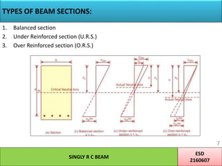
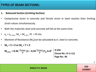
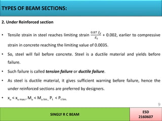
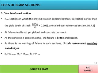
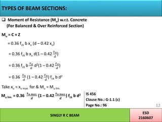
![TYPES OF BEAM SECTIONS:
Moment of Resistance (Mu) w.r.t. Steel (For Under Reinforced Section)
Mu = T × Z
= 0.87 fy Ast × [d – (0.42 xu)]
= 0.87 fy Ast × [d – (0.42
0.87 𝑓𝑦 𝐴 𝑠𝑡
0.36 𝑓 𝑐𝑘 𝑏
)]
= 0.87 fy Ast × [d –
𝑓𝑦 𝐴 𝑠𝑡
𝑓 𝑐𝑘 𝑏
]
ESD
2160607
10
SINGLY R C BEAM
Mu = 0.87 fy Ast d [1 –
𝒇 𝒚 𝑨 𝒔𝒕
𝒇 𝒄𝒌 𝒃 𝒅
]
IS 456
Clause No.: G-1.1 (b)
Page No.: 96](https://image.slidesharecdn.com/singlyrcbeam-200516080530/85/Singly-R-C-Beam-10-320.jpg)
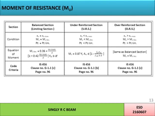


This document discusses stress diagrams and design considerations for singly reinforced concrete beams. It covers notation, stress conditions, types of failure, and formulas for moment of resistance. The key points are: 1) A stress diagram shows the compression and tension zones of a beam based on the depth of the neutral axis. The moment of resistance depends on the neutral axis location. 2) Beam sections can be balanced, under-reinforced, or over-reinforced depending on when concrete or steel yields. Under-reinforced sections are preferred. 3) Formulas are provided to calculate the moment of resistance based on the steel or concrete stresses for different section types. Reinforcement criteria specify minimum and maximum steel ratios.


![Geotechnical Engineering-II [Lec #27: Infinite Slope Stability Analysis]](https://cdn.slidesharecdn.com/ss_thumbnails/27-181125070251-thumbnail.jpg?width=640&height=640&fit=bounds)