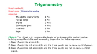
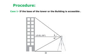
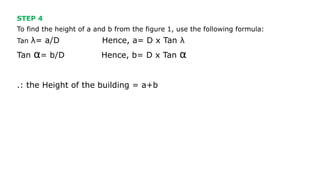
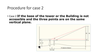
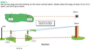
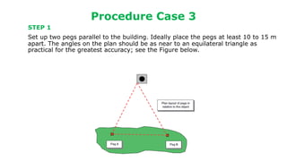
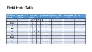
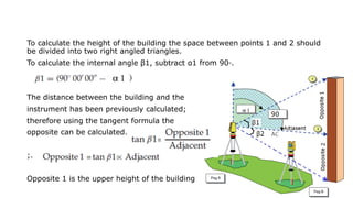
The document describes procedures for measuring the height of an inaccessible building using a theodolite. It outlines 3 cases: 1) the building base is accessible, 2) the base is inaccessible but 3 points lie on the same vertical plane, and 3) the base is inaccessible and points do not lie on the same plane. For each case, it provides step-by-step instructions, formulas used, and an example field note table. Calculations involve using trigonometric functions like tangent and sine based on measured angles and distances to calculate heights.
Measuring of Horizontal angle Practical PartBahzad5
Surveying Engineering
Plane and Applied surveying 2
Theodolite practical part 1
Report number(1)
Report name: Setting up Theodolite Instrument Measuring Horizontal and Vertical Angle.
Apparatus:
Theodolite Instrument 1 No.
Tripod 1 No.
Pin 3 Nos.
Tape 1 No.
Range pole 2 Nos.
Object :
1. To perform temporary adjustment of theodolite instrument
2. Measuring of Horizontal angle H.A Face Left (F.L) and face right(F.R) .
3. Measuring of Vertical angle V.A Face Left (F.L) and face right(F.R)
Measuring Horizontal Angle
There are three methods of measuring horizontal angles:
i) Ordinary Method
ii) Repetition Method.
iii) Reiteration Method.
Angular measurement :
Angular measurement is made using surveying instruments which measure
both horizontally and vertically in degrees. Degrees are sexagesimal units which are subdivided into minutes and seconds in exactly the same manner as time.
Calculation and Measuring Horizontal Angle
i)Ordinary Method. To measure horizontal angle:
1-Set up the theodolite at station point ( O)
Direct telescope to point A and set the horizontal angle to the zero or 360°.
2-Turn the instrument clockwise and direct the telescope towards B and read the horizontal B and record both the readings.
3-The reading angles at B gives the
value of the angle AOB directly.
4-Change the face of the instrument
and repeat the whole process. The mean of the two readings gives
the second value of the angle AOB which should be approximately or
exactly equal to the previous value.
5-The mean of the two values of the angle AOB ,one with face left
and the other with face right ,gives the ,required angle free from all
instrumental errors.
ii) Repetition Method.
This method is used for very accurate work.
The No. of repetitions made usually in this method is
six, three with the face left and three with the face right
.In this way ,angles can be measured to a finer degree of
accuracy .
iii) Reiteration Method
It is generally preferred when several angles are to be
measured at a particular station.
This method consists in measuring several
angles successively and finally closing the Horizon at the starting point. The final reading of the point A should be same as its initial reading.
*Measuring Vertical Angle
Vertical Angle :
A vertical angle is an angle between the inclined line of sight and the horizontal. It may be an angle of elevation or depression according as the object is above or below the horizontal plane.
Prepared by:
Asst. Prof. Salar K.Hussein
Mr. Kamal Y.Abdullah
Asst.Lecturer. Dilveen H. Omar
Erbil Polytechnic University
Technical Engineering College
Civil Engineering Department
Surveying Engineering
Contour & Contouring
In this lecture we will cover
definitions.
Characteristics of contour lines.
Contours used by Engineers .
Methods of locating contour.
Method of Interpolation Contours.
Contour & Contouring
A map showing the natural and cultural features as well
as showing the nature of the surface of the land (topography of the
land) of the up and downs and its representation in (3D)three
dimensions.
A contour is a line drawn on a plan joining all points of the same
height above or below a datum.
Or A contour line
is a line that passes through points having the same elevation.
contour interval
is the constant vertical distance(VD) between any two
consecutive contours is called the contour interval
. The contour interval on this map is 20m
-The choice of suitable contour interval depends on several
factors.
-Topographic Maps
-Characteristics of contour lines.
-Contours are used by Engineers to:
-Methods of locating contour:
A- The direct methods
1- Level and staff method.
2- Plan table and alidade method.
Direct method procedure:
In this method the actual contour is pegged out on the ground and its
planimetric position located. A back-sight is taken to an appropriate BM and
the HPC of the instrument is obtained, say( 34.800m.) A staff reading of
0.800m would then place the foot of the staff at the( 34m )contour level. The
staff is then moved throughout the terrain area, with its position pegged at
every 0.800m reading. In this way the 34m contour is located. Similarly a
staff reading of (1.800m) gives the 33m contour and so on. The planimetric position of the contour needs to be located using an appropriate survey technique.
1- Grid method:-
Methods of Contouring
B- Indirect contouring
*Method of Interpolation Contours.
-Plotting contours.
Prepared by:
Asst. Prof. Salar K.Hussein
Mr. Kamal Y.Abdullah
Asst.Lecturer. Dilveen H. Omar
Erbil Polytechnic University
Technical Engineering College
Civil Engineering Department
Introduction, electromagnetic spectrum, electromagnetic distance measurement, types of EDM instruments, electronic digital theodolites, total station, digital levels, scanners for topographical survey, global positioning system.
Plane and Applied Surveying 2
Trigonometric Levelling theory
-What is Trigonometric Levelling.
-Measurement Using Trigonometry.
Measurement Using Trigonometry.
-The vertical angle and the slope distance between the two points are measured.
-If You Are Able To Get to the base of the Tower Or The Building.
Trigonometric Levelling
I- If base of the object is accessible:
1. Instrument at station A is lower than station B.
The three points (A, B, and O) are on the same vertical plane
2 Instrument at point B is lower than A.
The three points (A, B, and O) are on the same vertical plane.
3. If the two instrument heights were at the same level.
*Example:
Find the vertical height of electrical column over a hill. The reading is taken from two
instrument station (P, and R), and the horizontal distance between thereof is (60 m). The
horizontal angle of RPQ = 60°30′
, and the horizontal angle of PRQ = 68°18′
. The vertical
angle from P to Q =10°12′
, and the vertical angle from R to Q = 10°48′
.
Find the reduced level of point Q if the reduced level of (B.M) = 435.065m and the staff
reading from P and Rare (1.965, and 2.055) m respectively. And then check the result.
Asst. Prof. Salar K.Hussein
Mr. Kamal Y.Abdullah
Asst.Lecturer. Dilveen H. Omar
Erbil Polytechnic University
Technical Engineering College
Civil Engineering Department
surveying_module-3-trigonometric-leveling by Denis Jangeed.pdfDenish Jangid
surveying_module-3-Trigonometric leveling by Denis Jangeed
Methods of Observation
Method of determining the elevation of
To obtain R.L of top of a ten storeyed building
following observation were taken.
Indirect levelling on a rough
terrain
a point by theodolite
• There are main three cases to determine the
R.L of any point.
• Case : 1 :- Base of Object accessible.
• Case : 2 :- Base of object inaccessible,
instrument station in the vertical plane as the
elevated object.
• Case : 3 :- Base of the object inaccessible ,
instrument stations not in the same vertical
plane as the elevated object.
There may be two case
A. Instrument axis at same level
B. Instrument axis at different level
Angle of elevation
Height of the instrument
Calculate reduce level of the top of the tower
from the following data.
Indirect levelling on a steep slope
This is based on the surveying branch.. which shows 3 cases here.. for civil engineering students .. and as well as also who want to know about what is Trigonometric leveling..
Abstract— This research paper with how to facilitate and manage surveying instrument theodolite and total satiation and take more accuracy for civil works methods to accomplish modernized and cost effective urban survey with best achievable accuracy. This is done by surveying methods with modern methods from both theoretical and practical point of view. At first, a theoretical assessment process on a tradition urban planning project in India is performed by replacing other instrument of surveying techniques previously used with more applicable surveying techniques as theodolite and total stations, regarding different matters such as applicability, cost and accuracy. After approving the main idea of this modernization process, a practical urban planning case study is performed using total station, geodetic GPS receivers and GPS navigators, on a private sectors The applied surveying techniques showed high efficiency regarding cost and effort, while saving observation time reaching to 80%. Accordingly, the adopted practical application proved to be beneficial for all civil sites.
ENGR 102B Microsoft Excel Proficiency LevelsPlease have your in.docxYASHU40
ENGR 102B: Microsoft Excel Proficiency Levels
Please have your instructor or TA initial each level as you complete it. If you need additional help, ask the TAs or use the help guide within Excel.
Once you master Excel Levels I through IV, you can note Excel as a skill on your resume!
Please see D2L Content for this week for your Excel Homework assignment (individual), which is due via D2L Dropbox by the due date specified in the D2L News for your section.
If you use a Mac, please be sure to submit your homework in a format that the grader and instructor can open on a PC.
Level I: Basic Functions Initials _______
1. Calculating an Average: Calculate the arithmetic average of the 5 values listed below. Enter the values in cells A2 through A6. Place a descriptive label in cell A1.
3.6, 3.8, 3.5, 3.7, 3.6
First, calculate the average the long way, by summing the values and dividing by 5:
You will enter the following formula into a blank cell to accomplish this:
=(A2+A3+A4+A5+A6)/5
Second, calculate the average using Excel’s AVERAGE( ) function by entering the following formula in a cell:
=AVERAGE(cellrange)
Replace the “cellrange” with the actual addresses in your spreadsheet of the range of cells holding the five values (i.e., for this problem, the cell range is A2:A6).
2. Determining Velocities (in kph): Some friends at the University of Calgary are coming south for spring break. Help them avoid a speeding ticket by completing a velocity conversion worksheet that calculates the conversion from mph to kph in increments of 10 from 10 to 100. A conversion factor you will need is 0.62 miles/km; you will need this factor to convert from miles/hour to km/hour. Place the conversion factor in its own cell and then reference it in your conversion calculations using absolute cell referencing (e.g., $C$2). Refer to the CBT video on Absolute and Relative Cell Referencing from the “Preparation for the Excel Workshop” assignment if you don’t remember how to do this.
Level II: Advanced Functions Initials _______
1. Projectile Motion I: (See following page for Fig. 1 Excel chart) A projectile is launched at the angle 35o from the horizontal with a velocity equal to 30 m/s. Neglecting air resistance and assuming a horizontal surface, determine how far away from the launch site the projectile will land.
To answer this problem, you will need:
1. Excel’s trigonometry functions to handle the 35o angle, and
2. Equations relating distance to velocity and acceleration
When velocity is constant, as in the horizontal motion of our particle (since we’re neglecting air resistance), the distance traveled is simply the initial horizontal velocity times the time of flight:
(Equation 1)
What keeps the projectile from flying forever is gravity. Since the gravitational acceleration is constant, the vertical distance traveled becomes
(Equation 2)
Because the projectile ends up back on the ground, the final value of y is zero (a hor ...
دليل تجارب الاسفلت المختبرية - Asphalt Experiments Guide LaboratoryBahzad5
الجامعة التكنولوجية
قسم هندسة البناء والإنشاءات
فرع هندسة الطرق والجسور
مختبر الأسفلت
دليل تجارب الاسفلت المختبرية
Asphalt Experiments Guide Laboratory
:أعداد
م.د. زينب ابراهيم قاسم
م شرف مختبر الاسفلت
University of Technology
Building and Construction
Engineering Department
Highways and Bridges Engineering Branch
Asphalt Laboratory
CONDITIONS OF CONTRACT FOR WORKS OF CIVIL ENGINEERING CONSTRUCTIONBahzad5
FEDERATION INTERNATIONALE DES INGENIEURS-CONSEILS
CONDITIONS OF CONTRACT
FOR WORKS OF CIVIL
ENGINEERING CONSTRUCTION
PART I GENERAL CONDITIONS
WITH FORMS OF TENDER AND AGREEMENT
FOURTH EDITION 1987
Reprinted 1988 with editorial amendments
Reprinted 1992 with further amendments
الشروط العامة لمقاولات اعمال الهندسة المدنيةBahzad5
الشروط العامة لمقاولات اعمال الهندسة المدنية ((بقسميها الاول والثاني)) المعدة من وزارة التخطيط مع اخر التعديلات عليها بغداد 2002
توزيع المكتبة القانونية - بغداد
GENERAL CONDITIONS FOR CONTRACTS OF CIVIL ENGINEERING WORKS Bahzad5
REPUBLIC OF IRAQ
MINISTRY OF PLANNING
LEGAL DEPARTMENT
GENERAL CONDITIONS
FOR
CONTRACTS OF CIVIL ENGINEERING WORKS
PART I & II
PREPARED BY SPECIAL COMMITTEE AND
APPROVED BY THE PLANNING BOARD
JUNE 1973
Dar Al-Hurriyah
Al-Jamhurriyah Press, Baghdad
The Planning Board at its fifth meeting held on 12/6/1972 approved
these conditions vide resolution No. 2 and enforced the distribution
thereof to Ministries and Public establishments to act accordingly when
announcing tenders and adhering to the application thereof in all
contracts of civil engineering works together with the observance of
accuracy in the application of the second part for these conditions as to
harmonize with the volume and nature of each contract.
Hybrid optimization of pumped hydro system and solar- Engr. Abdul-Azeez.pdffxintegritypublishin
Advancements in technology unveil a myriad of electrical and electronic breakthroughs geared towards efficiently harnessing limited resources to meet human energy demands. The optimization of hybrid solar PV panels and pumped hydro energy supply systems plays a pivotal role in utilizing natural resources effectively. This initiative not only benefits humanity but also fosters environmental sustainability. The study investigated the design optimization of these hybrid systems, focusing on understanding solar radiation patterns, identifying geographical influences on solar radiation, formulating a mathematical model for system optimization, and determining the optimal configuration of PV panels and pumped hydro storage. Through a comparative analysis approach and eight weeks of data collection, the study addressed key research questions related to solar radiation patterns and optimal system design. The findings highlighted regions with heightened solar radiation levels, showcasing substantial potential for power generation and emphasizing the system's efficiency. Optimizing system design significantly boosted power generation, promoted renewable energy utilization, and enhanced energy storage capacity. The study underscored the benefits of optimizing hybrid solar PV panels and pumped hydro energy supply systems for sustainable energy usage. Optimizing the design of solar PV panels and pumped hydro energy supply systems as examined across diverse climatic conditions in a developing country, not only enhances power generation but also improves the integration of renewable energy sources and boosts energy storage capacities, particularly beneficial for less economically prosperous regions. Additionally, the study provides valuable insights for advancing energy research in economically viable areas. Recommendations included conducting site-specific assessments, utilizing advanced modeling tools, implementing regular maintenance protocols, and enhancing communication among system components.
Student information management system project report ii.pdfKamal Acharya
Our project explains about the student management. This project mainly explains the various actions related to student details. This project shows some ease in adding, editing and deleting the student details. It also provides a less time consuming process for viewing, adding, editing and deleting the marks of the students.
Immunizing Image Classifiers Against Localized Adversary Attacksgerogepatton
This paper addresses the vulnerability of deep learning models, particularly convolutional neural networks
(CNN)s, to adversarial attacks and presents a proactive training technique designed to counter them. We
introduce a novel volumization algorithm, which transforms 2D images into 3D volumetric representations.
When combined with 3D convolution and deep curriculum learning optimization (CLO), itsignificantly improves
the immunity of models against localized universal attacks by up to 40%. We evaluate our proposed approach
using contemporary CNN architectures and the modified Canadian Institute for Advanced Research (CIFAR-10
and CIFAR-100) and ImageNet Large Scale Visual Recognition Challenge (ILSVRC12) datasets, showcasing
accuracy improvements over previous techniques. The results indicate that the combination of the volumetric
input and curriculum learning holds significant promise for mitigating adversarial attacks without necessitating
adversary training.
Final project report on grocery store management system..pdfKamal Acharya
In today’s fast-changing business environment, it’s extremely important to be able to respond to client needs in the most effective and timely manner. If your customers wish to see your business online and have instant access to your products or services.
Online Grocery Store is an e-commerce website, which retails various grocery products. This project allows viewing various products available enables registered users to purchase desired products instantly using Paytm, UPI payment processor (Instant Pay) and also can place order by using Cash on Delivery (Pay Later) option. This project provides an easy access to Administrators and Managers to view orders placed using Pay Later and Instant Pay options.
In order to develop an e-commerce website, a number of Technologies must be studied and understood. These include multi-tiered architecture, server and client-side scripting techniques, implementation technologies, programming language (such as PHP, HTML, CSS, JavaScript) and MySQL relational databases. This is a project with the objective to develop a basic website where a consumer is provided with a shopping cart website and also to know about the technologies used to develop such a website.
This document will discuss each of the underlying technologies to create and implement an e- commerce website.
Water scarcity is the lack of fresh water resources to meet the standard water demand. There are two type of water scarcity. One is physical. The other is economic water scarcity.
Saudi Arabia stands as a titan in the global energy landscape, renowned for its abundant oil and gas resources. It's the largest exporter of petroleum and holds some of the world's most significant reserves. Let's delve into the top 10 oil and gas projects shaping Saudi Arabia's energy future in 2024.
Cosmetic shop management system project report.pdfKamal Acharya
Buying new cosmetic products is difficult. It can even be scary for those who have sensitive skin and are prone to skin trouble. The information needed to alleviate this problem is on the back of each product, but it's thought to interpret those ingredient lists unless you have a background in chemistry.
Instead of buying and hoping for the best, we can use data science to help us predict which products may be good fits for us. It includes various function programs to do the above mentioned tasks.
Data file handling has been effectively used in the program.
The automated cosmetic shop management system should deal with the automation of general workflow and administration process of the shop. The main processes of the system focus on customer's request where the system is able to search the most appropriate products and deliver it to the customers. It should help the employees to quickly identify the list of cosmetic product that have reached the minimum quantity and also keep a track of expired date for each cosmetic product. It should help the employees to find the rack number in which the product is placed.It is also Faster and more efficient way.
2. Trigonometry
Report number(3)
Report name :
Apparatus
Theodolite instruments 1 No.
Range poles 1 No.
Tripod 2 Nos.
Surveyors’ pins 4 Nos.
Hammer 1 No.
Tape 1 No.
Object: The object is to measure the height of an inaccessible and accessible
building using theodolite and measuring angles for the following cases:
1. Base of object is accessible.
2. Base of object is not accessible and the three points are on same vertical plane.
3. Base of object is not accessible and the three points are not on same vertical
plane.
4. STEP 1
Set up the theodolite over a ground mark and take the angle to the top of the building
and an angle to the bottom of the building.
STEP 2
Measure the horizontal distance from the building to the ground mark.
STEP 3
Calculate the vertical angles. It is required to break the
formula down in to two right angle triangles.
As shown in the figure 1.
5. STEP 4
To find the height of a and b from the figure 1, use the following formula:
Tan λ= a/D Hence, a= D x Tan λ
Tan α= b/D Hence, b= D x Tan α
.: the Height of the building = a+b
6. Procedure for case 2
• Case 2 If the base of the tower or the Building is not
accessible and the three points are on the same
vertical plane.
7. STEP 1
Set up two pegs and the building on the same vertical plane. Ideally place the pegs at least 10 to 15 m
apart, see the Figure below.
Object
Object
Section
10-15 m
Staff
8. STEP 2
Set up and level the instrument (theodolite) over peg A.
STEP 3
Target the top and the bottom of the building in order to
vertical angle to be measured and book the readings on the
booking sheet. Then take a reading on staff (r1)
STEP 4
Move the instrument and set up the second over peg B.
Measure the vertical angle of the top and the bottom of the
building. Book the reading. Continue by taking and booking
the readings. Then take a reading on staff (r2)
9. Procedure for case 3
Case 3- If the base of the tower or the Building is not accessible and the three
points are not on the same vertical plane.
10. Procedure Case 3
STEP 1
Set up two pegs parallel to the building. Ideally place the pegs at least 10 to 15 m
apart. The angles on the plan should be as near to an equilateral triangle as
practical for the greatest accuracy; see the Figure below.
11. STEP 2
Set up and level the instrument (theodolite) over peg A. Take staff reading (r1)
STEP 3
Target the top and the bottom of the building in order to vertical angle to be
measured and book the readings on the booking sheet
STEP 4
Set the horizontal angel to zero (0 set) and target peg B. Book the horizontal reading.
As shown in the figure.
STEP 5
Move the instrument and set up the
second over peg B and target peg A.
measure the vertical angle of the top
and the bottom of the building. Book
the reading. Continue by taking and
booking the readings. Take staff
reading (r2)
STEP 6
Set the horizontal angel to zero (0 set) and
target peg B. Book the horizontal reading.
Staff
Object
13. Calculation For Case 1
I- If base of the object is accessible:
¨ 𝑆1 = 𝐷 tan ∝
¨ 𝑆2 = 𝐷 tan 𝛽
¨ ℎ = 𝑆1 + 𝑆2
¨ ℎ = 𝐷 (tan ∝ + tan 𝛽) BM
¨ figure 1
¨ RL of the object = RL of BM + S
Staff
S
h
14. Calculation For Case 2
𝑆 = 𝑟2 − 𝑟1 = 𝐻1 − 𝐻2
𝐻1 = 𝐷 tan ∝ ……………… (1)
𝐻2 = (𝑑 + 𝐷) tan 𝛽 ……… (2)
Subtract equation 1 and 2
𝐻1 − 𝐻2 = 𝐷 tan ∝ − 𝑑 tan 𝛽 − 𝐷 tan 𝛽
𝑆 + 𝑑 tan 𝛽 = 𝐷 (tan ∝ − tan 𝛽)
𝐷 =
𝑆 + 𝑑 tan 𝛽
tan ∝ − tan 𝛽
14
Case 2. The three points (A, B, and O) are on the same vertical plane.
B A O
15. Calculations For case 3
1- Calculate the horizontal angles in order to find the distance between the
instrument.
2-Calculate the angle for point C (angle A and B measured by theodolite)
Angle C= 180- (angle A + angle B )
3- To find the distance between the building and
The instrument we should use sine rule, As there
are no right angles.
The first objective is to calculate the length
of AB therefore use that part
of the formula and note the known data.
16. The first objective is to calculate the length of AC therefore use that part of the
formula and note the known data.
length AB is known
Hence, AC= x AB =D1 (AC is the length between the building and the instrument A)
Hence, BC= x AB = D2 (BC is the length between the building and the instrument B)
A
17. To calculate the height of the building the space between points 1 and 2 should
be divided into two right angled triangles.
To calculate the internal angle β1, subtract α1 from 90◦.
The distance between the building and the
instrument has been previously calculated;
therefore using the tangent formula the
opposite can be calculated.
;.
Opposite 1 is the upper height of the building
18. To Calculate the opposite on the lower of the building. To calculate the internal
angle β2 subtract 90◦ from α2:
To calculate the lower height of the building:
Add both Opposite 1 and Opposite 2
to calculate the overall height of the
building.
Opposite 1 + Opposite 2 = Overall height of building.