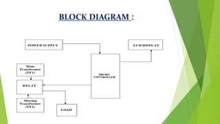
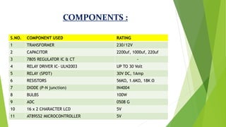
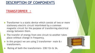
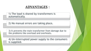
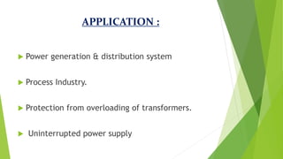
1. ABSTRACT:-
The transformer is a static device, which converts power from one level to another level.
The main aim is to protect the transformer under overload condition by load sharing.
Due to overload on transformer, the efficiency drops and windings get overheated and may get burnt.
Thus by sharing load on transformer, the transformer is protected. This will be done by connecting another transformer in parallel through a micro-controller.
The micro controller compares the load on the first transformer with a reference value. When the load exceeds the reference value, the second transformer will share the extra load.
Therefore, the two transformer work efficiently and damage is prevented. Main modules used here are sensing unit, control unit and micro-control.
A GSM modem is also used to inform the control station about switching.
The advantages of the project are transformer protection, uninterrupted power supply, and short circuit protection.
2. OBJECTIVE:-
To design & fabrication of a hardware which will monitor the performance of the load sharing process by taking power consumed by the load into consideration.
3. INTRODUCTION:-
Transformer is the vital component in the electric power transmission and distribution system.
The problems of overloading, voltage variation and heating effects are very common. It takes a lot of time for its repair and also involves lot of expenditure.
This work is all about protecting the transformer under overload condition. Due to overload the efficiency drops and the secondary winding gets overheated or it may be burnt.
So, by reducing the extra load, the transformer can be protected. This can be done by operating another transformer in parallel with main transformer through microcontroller and change over relay.
The microcontroller compares the load on the first transformer with a reference value. When the load exceeds the reference value, the slave transformer will automatically be connected in parallel with first transformer and share the extra load.
Therefore, a number of transformers work efficiently under overload condition and the damage can be prevented.
In this work, the slave transformers share the load of master transformer in the case of over load and over temperature conditions.
A sensor circuit containing microcontroller, current transformer etc. is designed to log the data from master transformer and if it is found to be in overload condition, immediately the slave transformer will be connected in the parallel to the master transformer and the load is shared.
Automatic load sharing of transformer using microcontroller
1. AUTOMATIC LOAD SHARING OF
TRANSFORMER USING MICROCONTROLLER
GUIDED BY: NAME - ENROLL NO.
PROF. DATTESH JOSHI GARVIT KATYAR 160050109012
SIDDHARTH 160050109075
PRAKHAR ANAND 160050109089
HIMALAY YADAV 160050109090
GROUP ID: 62533
2. ABSTRACT :
The transformer is a static device, which converts power from
one level to another level.
The main aim is to protect the transformer under overload
condition by load sharing.
Due to overload on transformer, the efficiency drops and
windings get overheated and may get burnt.
Thus by sharing load on transformer, the transformer is
protected. This will be done by connecting another
transformer in parallel through a micro-controller.
3. CONTINUE :
The micro controller compares the load on the first
transformer with a reference value. When the load
exceeds the reference value, the second transformer will
share the extra load.
Therefore, the two transformer work efficiently and
damage is prevented. Main modules used here are sensing
unit, control unit and micro-control.
A GSM modem is also used to inform the control station
about switching.
The advantages of the project are transformer
protection, uninterrupted power supply, and short circuit
protection.
4. OBJECTIVE :
To design & fabrication of a hardware
which will monitor the performance of the
load sharing process by taking power
consumed by the load into consideration.
5. INTRODUCTION :
Transformer is the vital component in the electric power
transmission and distribution system.
The problems of overloading, voltage variation and heating effects
are very common. It takes a lot of time for its repair and also
involves lot of expenditure.
This work is all about protecting the transformer under overload
condition. Due to overload the efficiency drops and the secondary
winding gets overheated or it may be burnt.
So, by reducing the extra load, the transformer can be protected.
This can be done by operating another transformer in parallel with
main transformer through microcontroller and change over relay.
6. CONTINUE :
The microcontroller compares the load on the first transformer with a
reference value. When the load exceeds the reference value, the slave
transformer will automatically be connected in parallel with first
transformer and share the extra load.
Therefore, a number of transformers work efficiently under overload
condition and the damage can be prevented.
In this work, the slave transformers share the load of master
transformer in the case of over load and over temperature conditions.
A sensor circuit containing microcontroller, current transformer etc. is
designed to log the data from master transformer and if it is found to
be in overload condition, immediately the slave transformer will be
connected in the parallel to the master transformer and the load is
shared.
9. CIRCUIT DESCRIPTION :
Firstly, the required operating voltage for Microcontroller 89C51 is 5V. Hence the 5V
D.C. power supply is needed by the same. This regulated 5V is generated by first
stepping down the 230V to 18V and 12 V operating voltage for relays. Hence
another supply is required to generate 12V.
The step downed a.c voltage is being rectified by the Bridge Rectifier. The diodes
used are 1N4007. The rectified a.c voltage is now filtered using a „C‟ filter.
Now the rectified, filtered D.C. voltage is fed to the Voltage Regulator. This
voltage regulator allows us to have a Regulated Voltage which is +5V.
We are using two voltage regulators i.e., 7805 and 7812. These voltage regulators
regulate 5v for microcontroller and 12v for relays. The rectified, filtered and
regulated voltage is again filtered for ripples using an electrolytic capacitor 100μF.
Now the output from this section is fed to 40th pin of 89c51 microcontroller to
supply operating voltage.
10. CONTINUE :
The microcontroller 89C51 with Pull up resistors at Port0 and
crystal oscillator of 11.0592 MHz crystal in conjunction with
couple of capacitors of is placed at 18th & 19th pins of 89c51 to
make it work (execute) properly.
The LCD is interfaced to Microcontroller. The data pins of LCD are
connected to Port 0. The control pins of LCD are connected to
Port 2.
One of the port 3 pin is connected to the secondary side of
transformer one through bridge rectifier and regulator to check
the status of the transformer one i.e. whether the power supply is
on or off to the transformer one through relay.
Relay is used to on & off the transformer occurred it is connected
to P2.0 microcontroller. The data pins of ADC are connected to
the port 1 of microcontroller.
11. COMPONENTS :
S.NO. COMPONENT USED RATING
1 TRANSFORMER 230/12V
2 CAPACITOR 2200uf, 1000uf, 220uf
3 7805 REGULATOR IC & CT -
4 RELAY DRIVER IC- ULN2003 UP TO 30 Volt
5 RELAY (SPDT) 30V DC, 1Amp
6 RESISTORS 56KΩ, 1.6KΩ, 18K Ω
7 DIODE (P-N junction) IN4004
8 BULBS 100W
9 ADC 0508 G
10 16 x 2 CHARACTER LCD 5V
11 AT89S52 MICROCONTROLLER 5V
12. DESCRIPTION OF COMPONENTS
TRANSFORMER :
Transformer is a static device which consist of two or more
stationary electric circuit interlinked by a common
magnetic circuit for the purpose of transferring electrical
energy between them.
The transfer of energy from one circuit to another takes
place without change in frequency.
In this project we are using 2 transformer- main & slave
transformers.
Rating of both the transformers- 230/12v & 3A.
13. CAPACITOR :
A capacitor is a passive two-terminal electronic component that stores
electrical energy in an electric field. The effect of a capacitor is known
as capacitance.
While some capacitance exists between any two electrical conductors in
proximity in a circuit, a capacitor is a component designed to add
capacitance to a circuit. The capacitor was originally known as a
condenser.
Most capacitors contain at least two electrical conductors often in the
form of metallic plates or surfaces separated by a dielectric medium.
A conductor may be a foil, thin film, sintered bead of metal, or an
electrolyte. The nonconducting dielectric acts to increase the capacitor's
charge capacity.
14. RELAY :
A relay is an electrically operated switch.
Relays allow one circuit to switch a second circuit which can
be completely separate from the first.
In this project we are using electromagnetic relay consists of
a multi-turn coil, wound on an iron core, to form
electromagnet. When the coil is energised, by passing
current through it, the core becomes temporarily
magnetised. The magnetised core attracts the iron armature
16. CONTINUE :
Low-power, high-performance CMOS 8-bit microcontroller
with 8KB of ISP flash memory.
The device uses Microchip high-density, nonvolatile
memory technology and is compatible with the industry-
standard 80C51 instruction set and pinout.
On-chip flash allows the program memory to be
reprogrammed in-system or by a conventional nonvolatile
memory programmer.
This powerful microcontroller is suitable for many
embedded control applications.
17. ADVANTAGES :
1) The load is shared by transformers is
automatically.
2) No manual errors are taking place.
3) It prevents the main transformer from damage due to
the problems like overload and overheats.
4) Un-interrupted power supply to the consumers
is supplied.
18. APPLICATION :
Power generation & distribution system
Process Industry.
Protection from overloading of transformers.
Uninterrupted power supply
19. OBSERVATION AND CONCLUSION :
In this paper, observed that if load on one transformer is
increases then the relay will sense the change in current
& microcontroller operates & slave transformers comes
automatically in operation to share the load.
The work on “Automatic load sharing of transformers” is
successfully designed, tested and a demo unit is
fabricated for operating three transformers in parallel to
share the load automatically with the help of change over
relay and relay driver circuit and also to protect the
transformers from overloading and thus providing an
uninterrupted power supply to the customers.
20. FUTURE SCOPE :
The future scope of our project is particularly in Substation.
In substations particularly during the peak hours there is a
need for the operation of additional transformer to supply
the additional load requirement.
Our project automatically connects the transformer under
critical loads.
Thus there is no need to operate both transformers under
normal loads, particularly during off peak hours. Thus power
is shared intelligently with the transformers in parallel.