Download as PDF, PPTX


![FOR TRAINING PURPOSE ONLY
Subject Code: AVI2041
Malaysian Institute of Aviation Technology
Issue No : 000
In the installation of DME equipment in an aircraft, the location of the antenna
is critical.
The antenna is a short stub, approximately 2.5 in. [6.35 cm] long, usually
mounted on the bottom of the fuselage.
Care must be taken in locating the antenna, because it can be blanked out
easily by obstructions such as landing gear or other antennas nearby.
It is recommended that manufacturer's instructions for installations in similar
aircraft be observed when making a new installation.
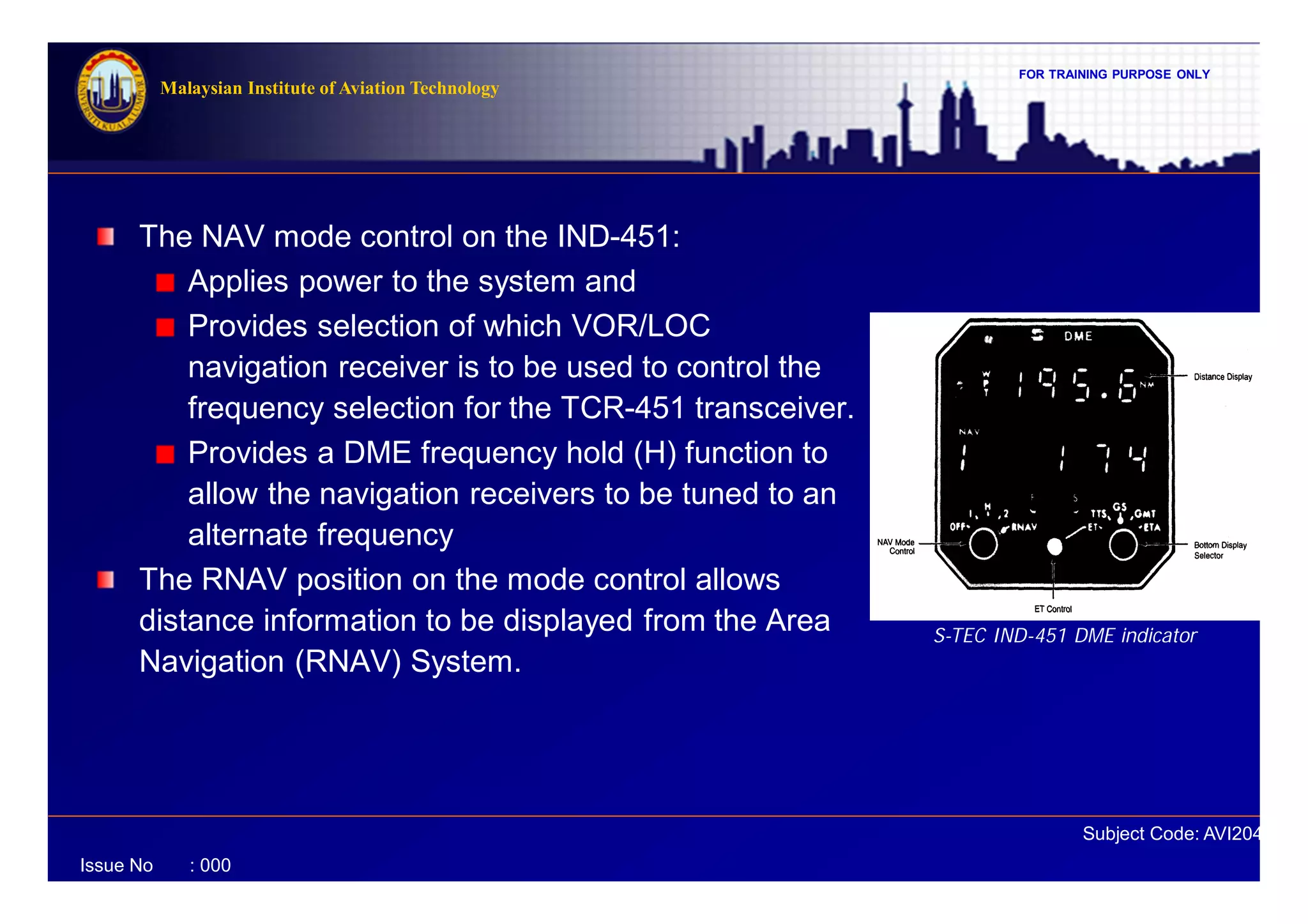
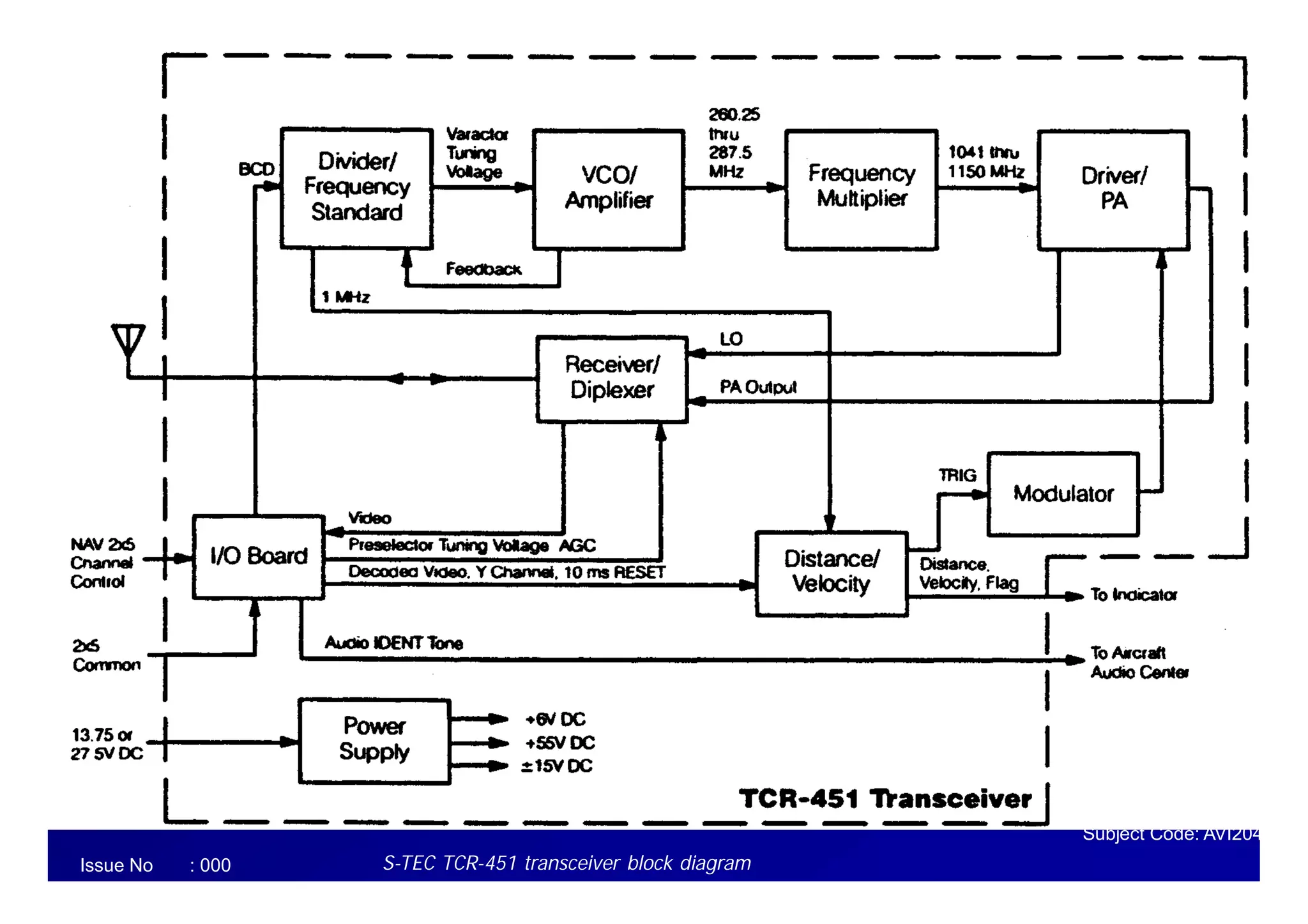
Functional Description (cont’d)](https://image.slidesharecdn.com/2-dme-140401230639-phpapp02/75/2-dme-54-2048.jpg)

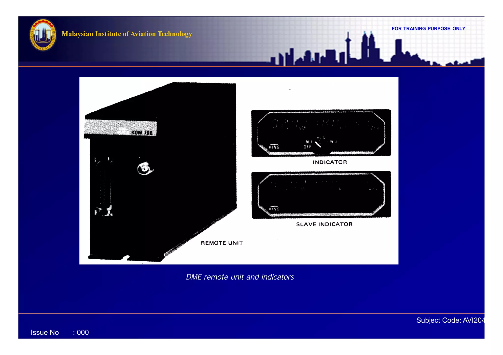
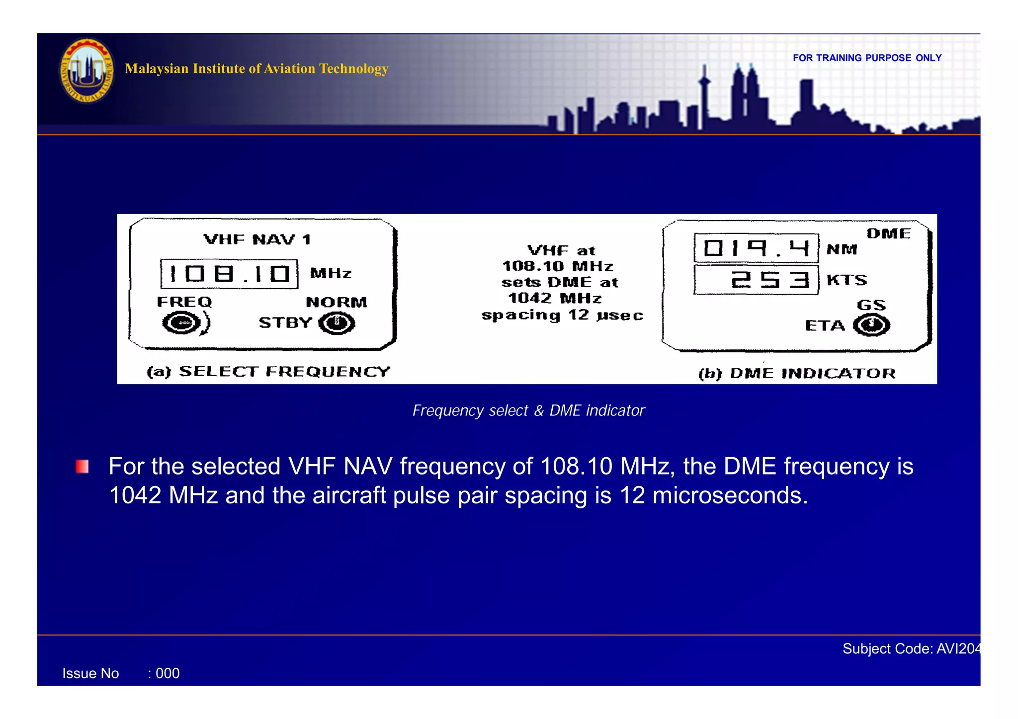
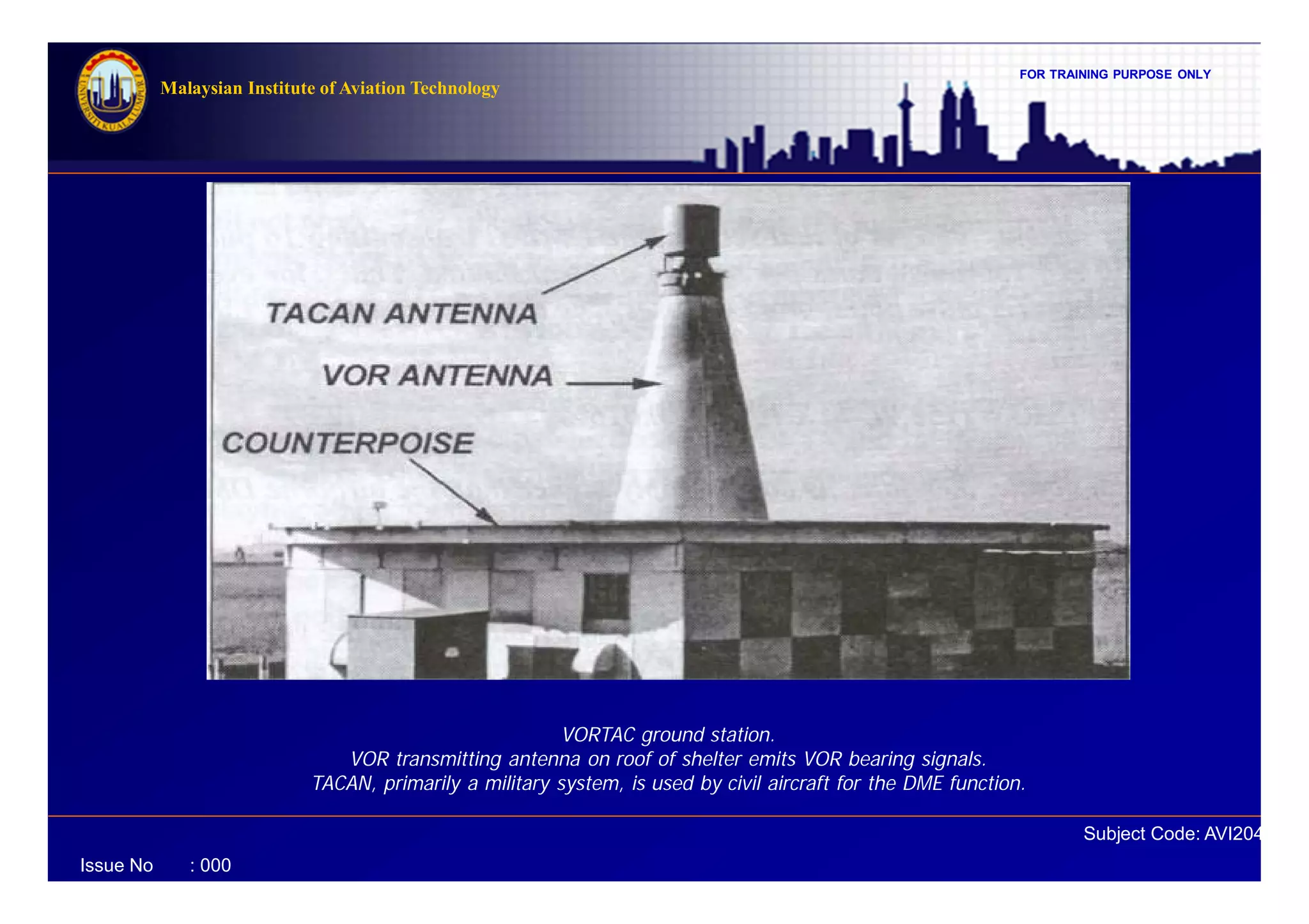


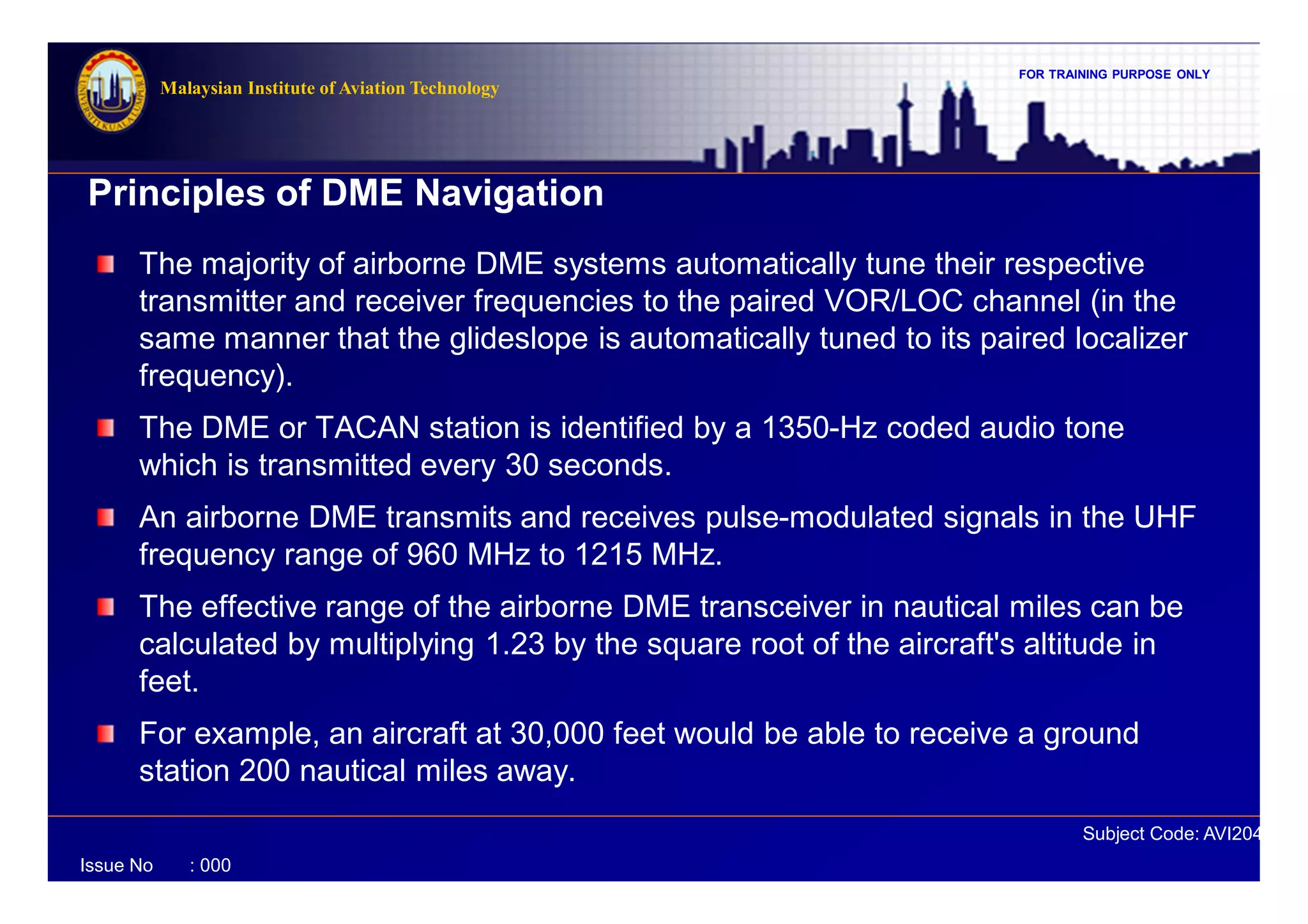
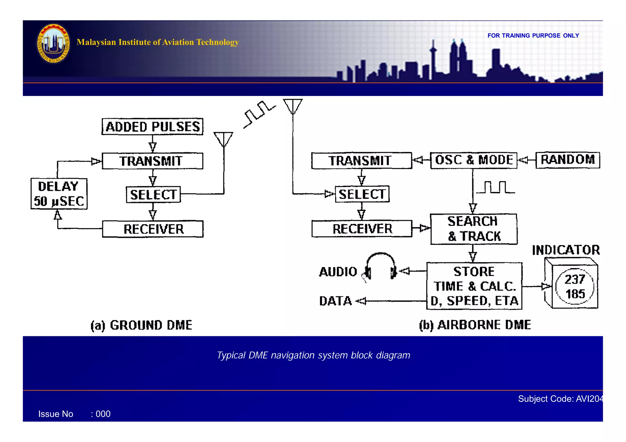
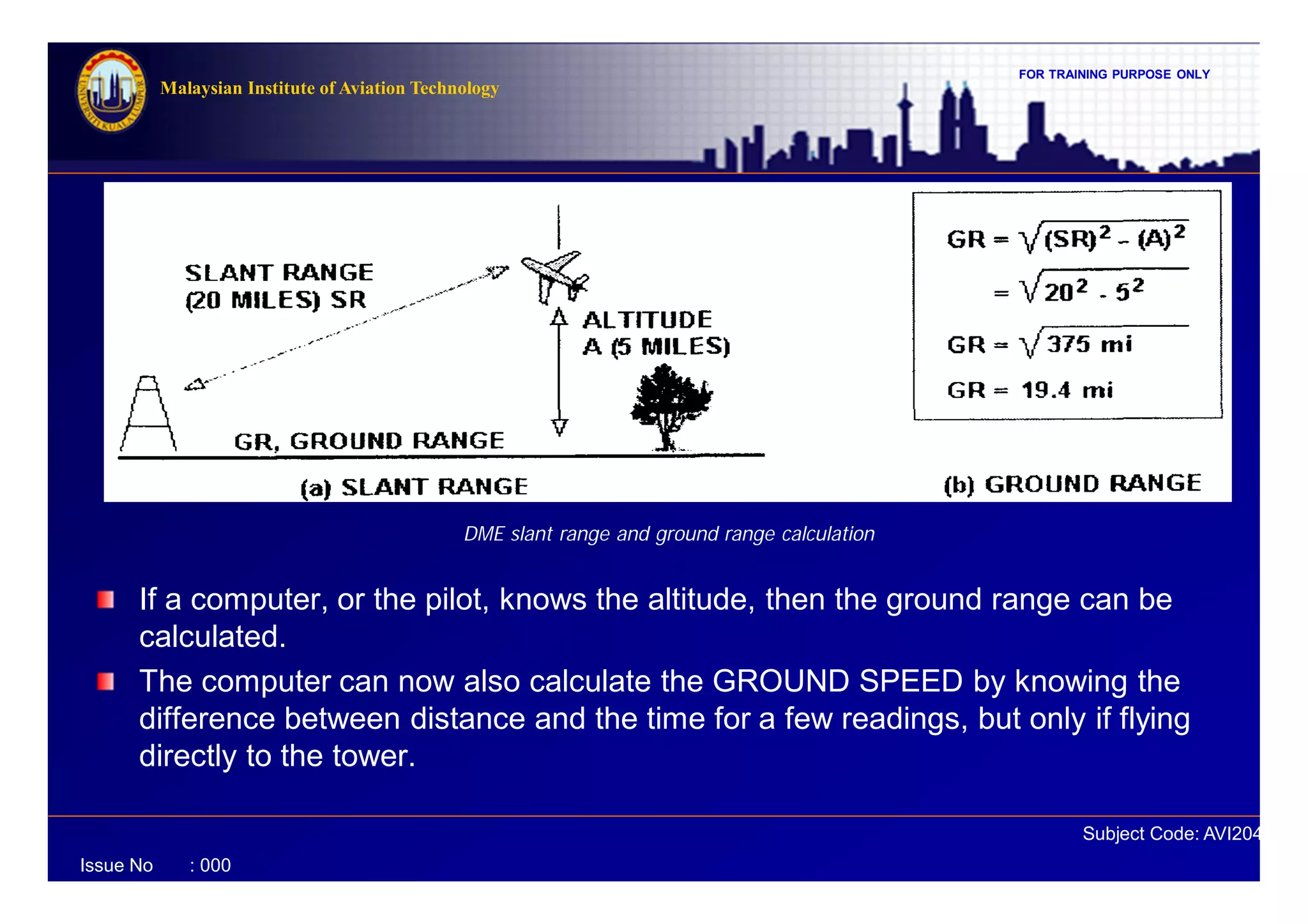
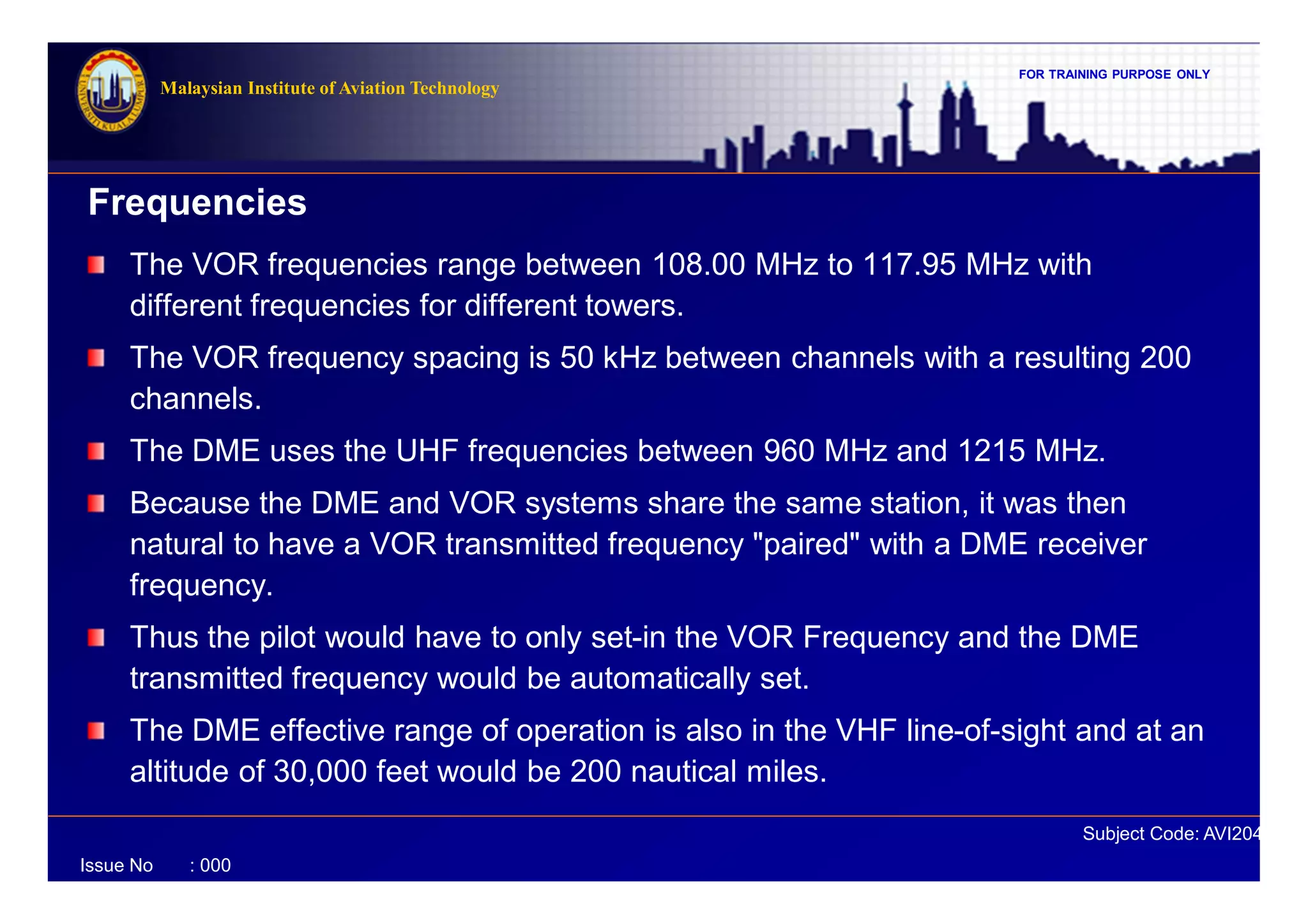
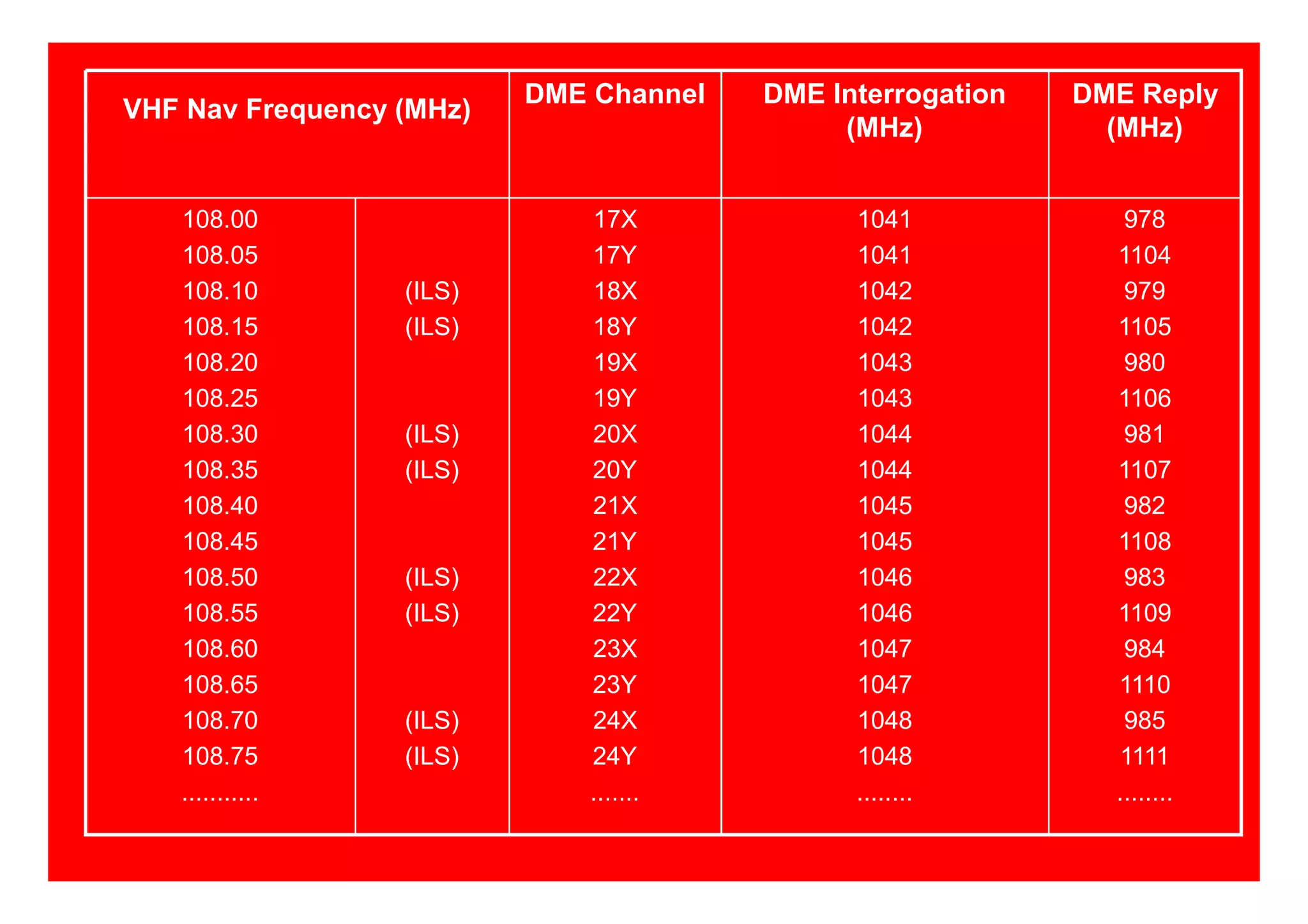
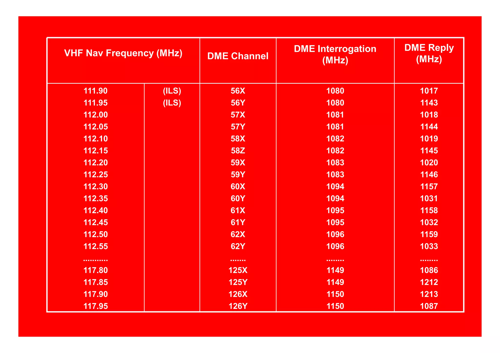
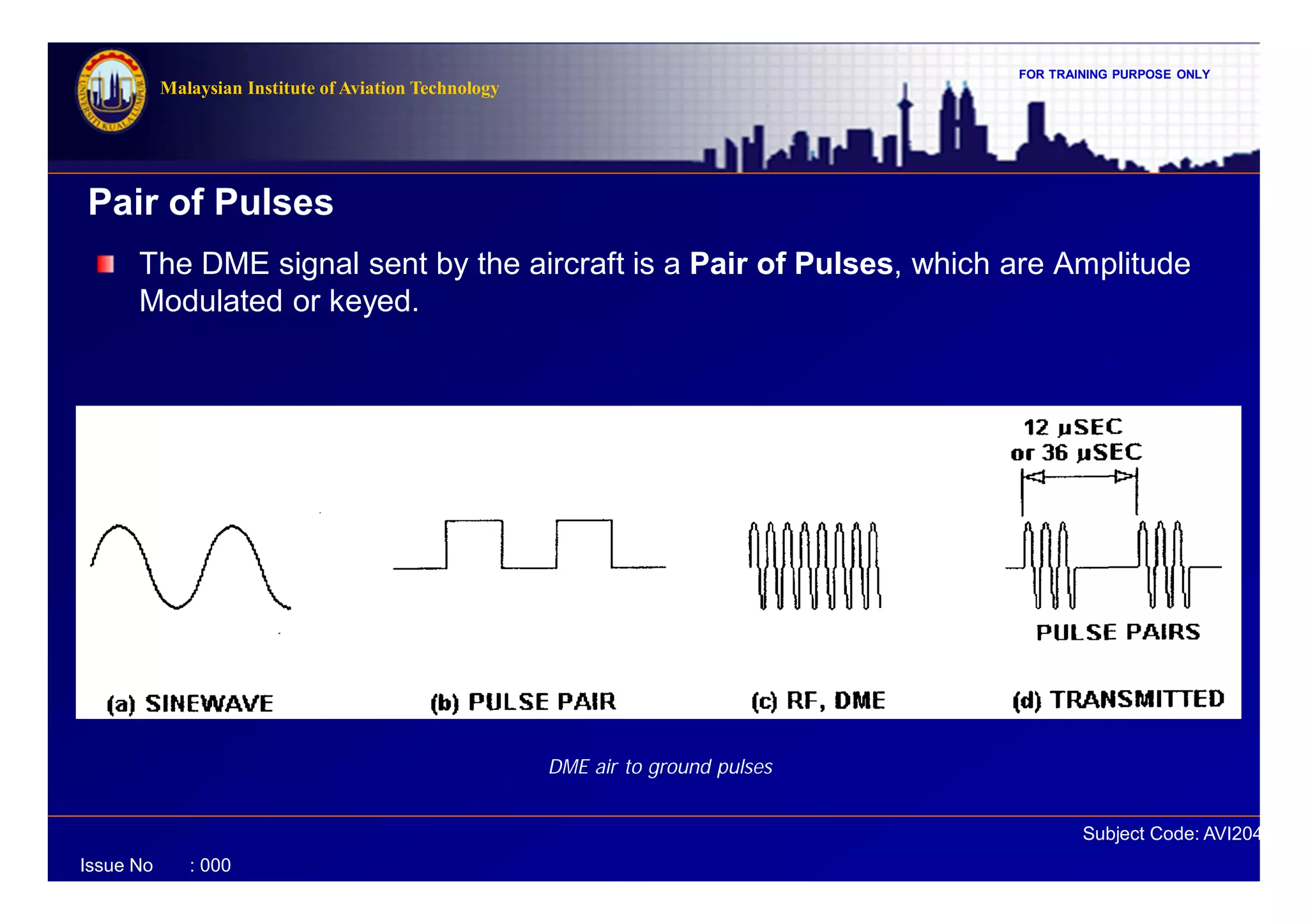
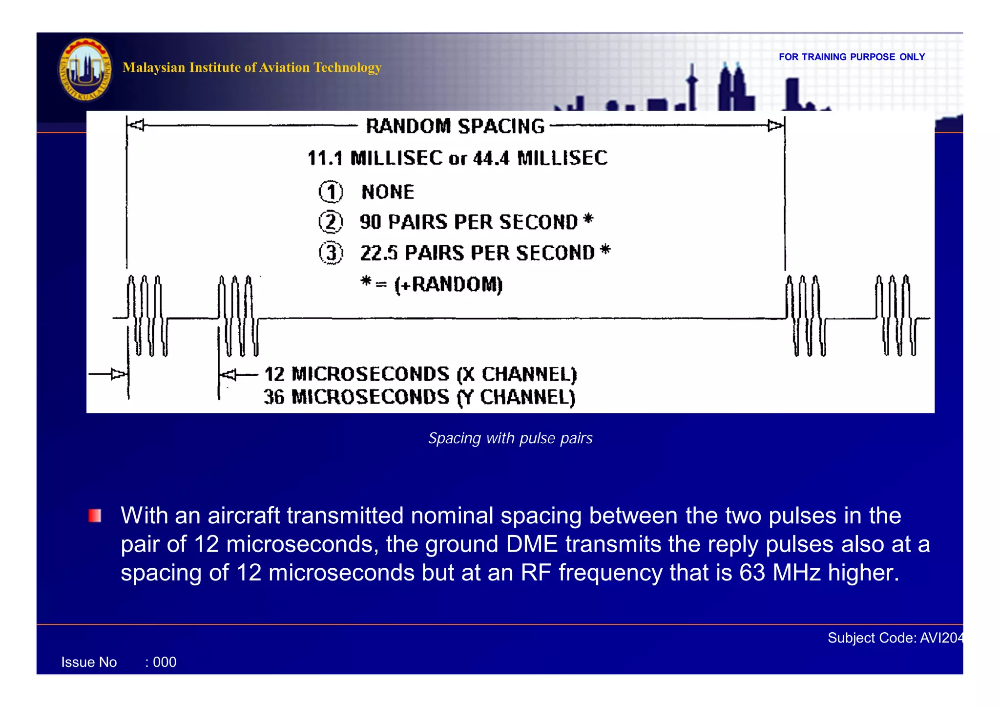
This document discusses Distance Measuring Equipment (DME) systems used for aircraft navigation. It describes how DME systems use radio pulses to measure the distance from an aircraft to a ground station. The document outlines the principles of DME navigation including slant range, frequencies used, pulse spacing, and how the distance is calculated from the round trip time of pulses. It provides details on DME system components, operation, indicators, and its relationship to VOR and TACAN navigation aids.