Download as PDF, PPTX

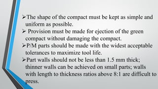
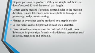
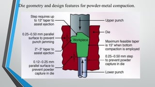
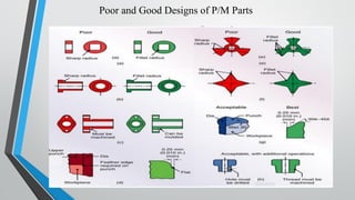
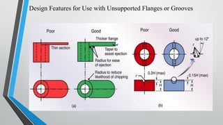
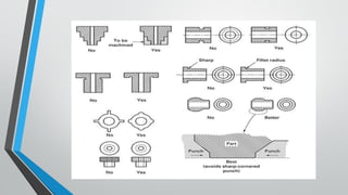

This document provides design considerations for powder metallurgy parts. Key points include: - Part shapes should be simple and uniform to allow for easy ejection from the die without damage. - Tolerances and wall thicknesses are limited, with minimum wall thickness of 1.5mm. - Simple steps and perpendicular letters can be included but must be carefully designed. - Radii cannot be pressed directly, chamfers must be used instead. - Die design must create strong tooling that can withstand pressing forces of 700MPa.