Downloaded 178 times

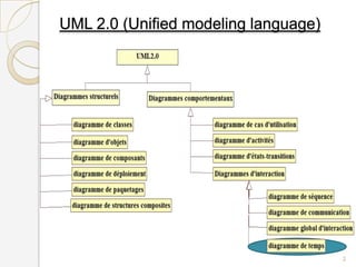


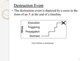
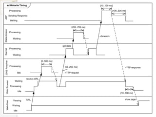


The document is a presentation on timing diagrams in UML. It discusses the key components of timing diagrams including lifelines, state timelines, duration constraints, time constraints, destruction events, and messages. It provides examples of how these components are used to model time-based behavior and interactions between components.