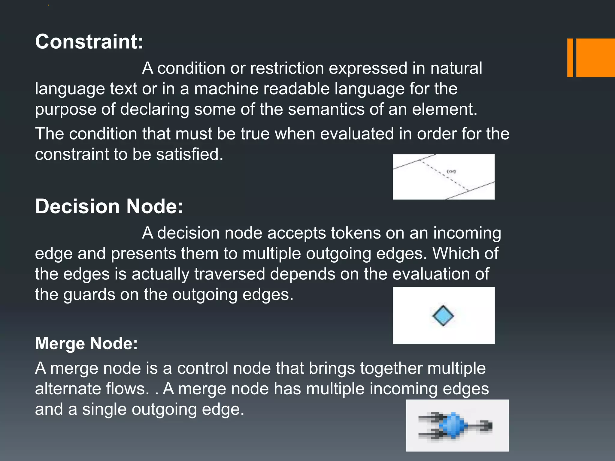
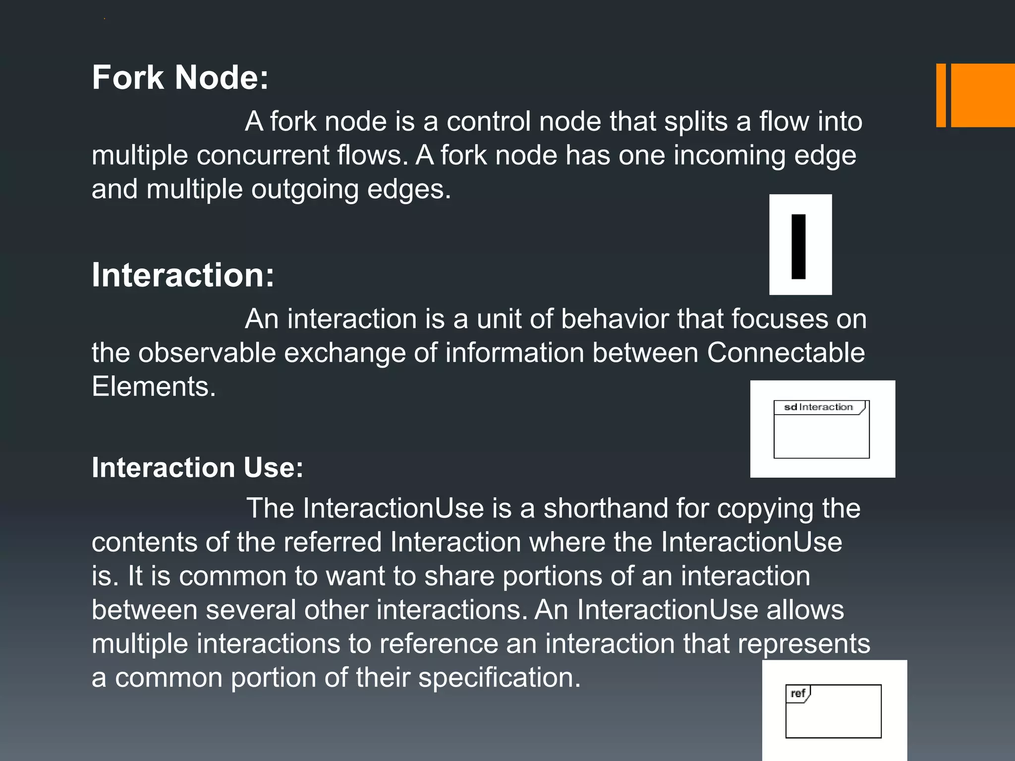
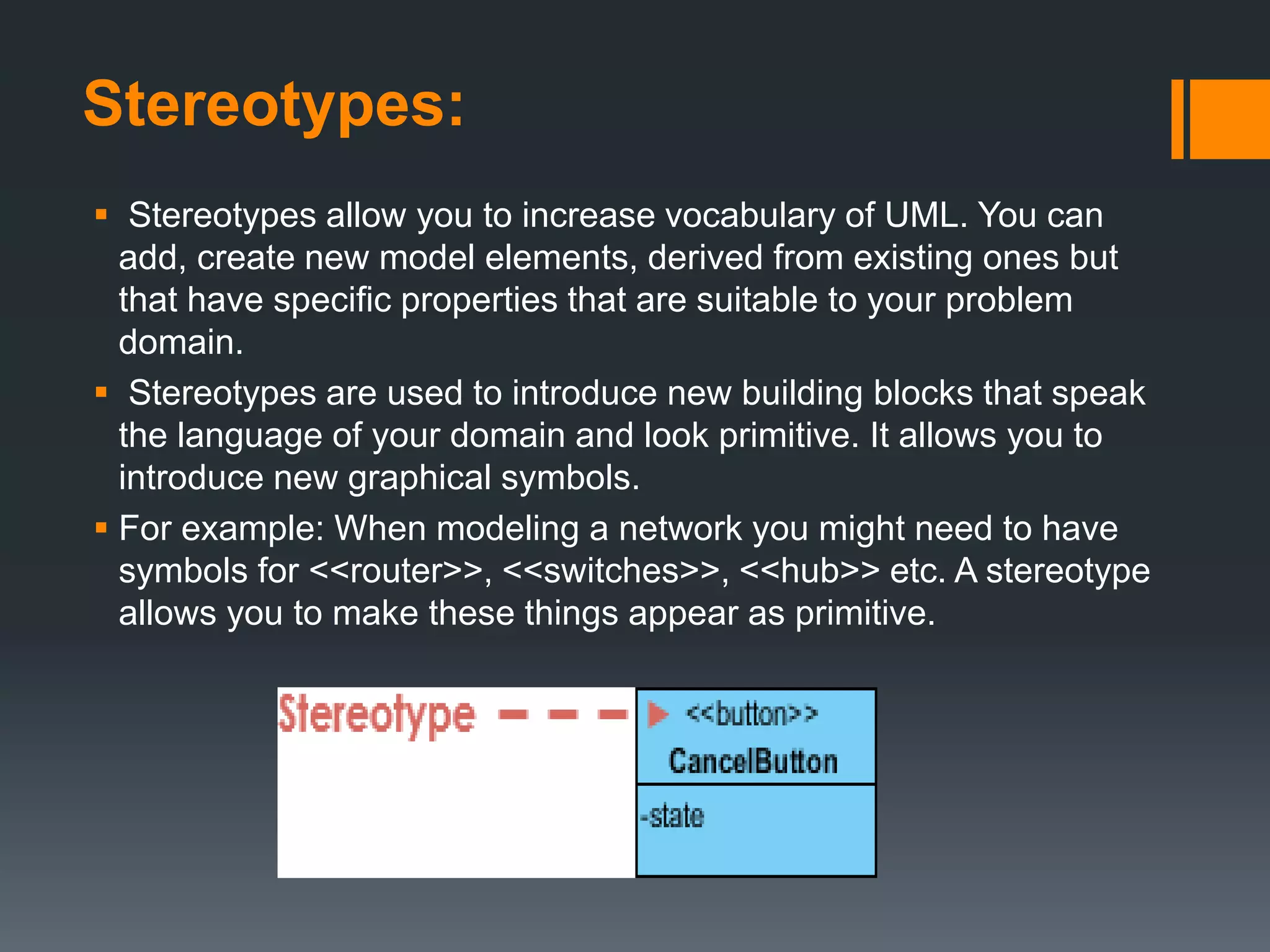
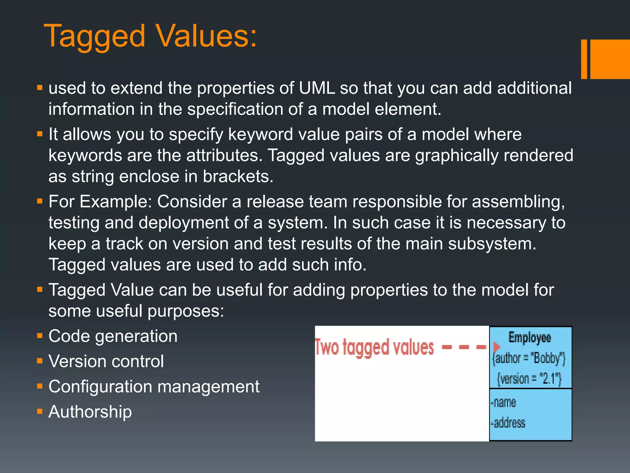
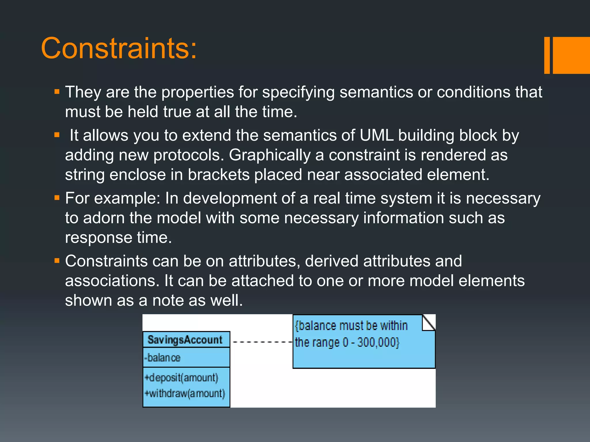
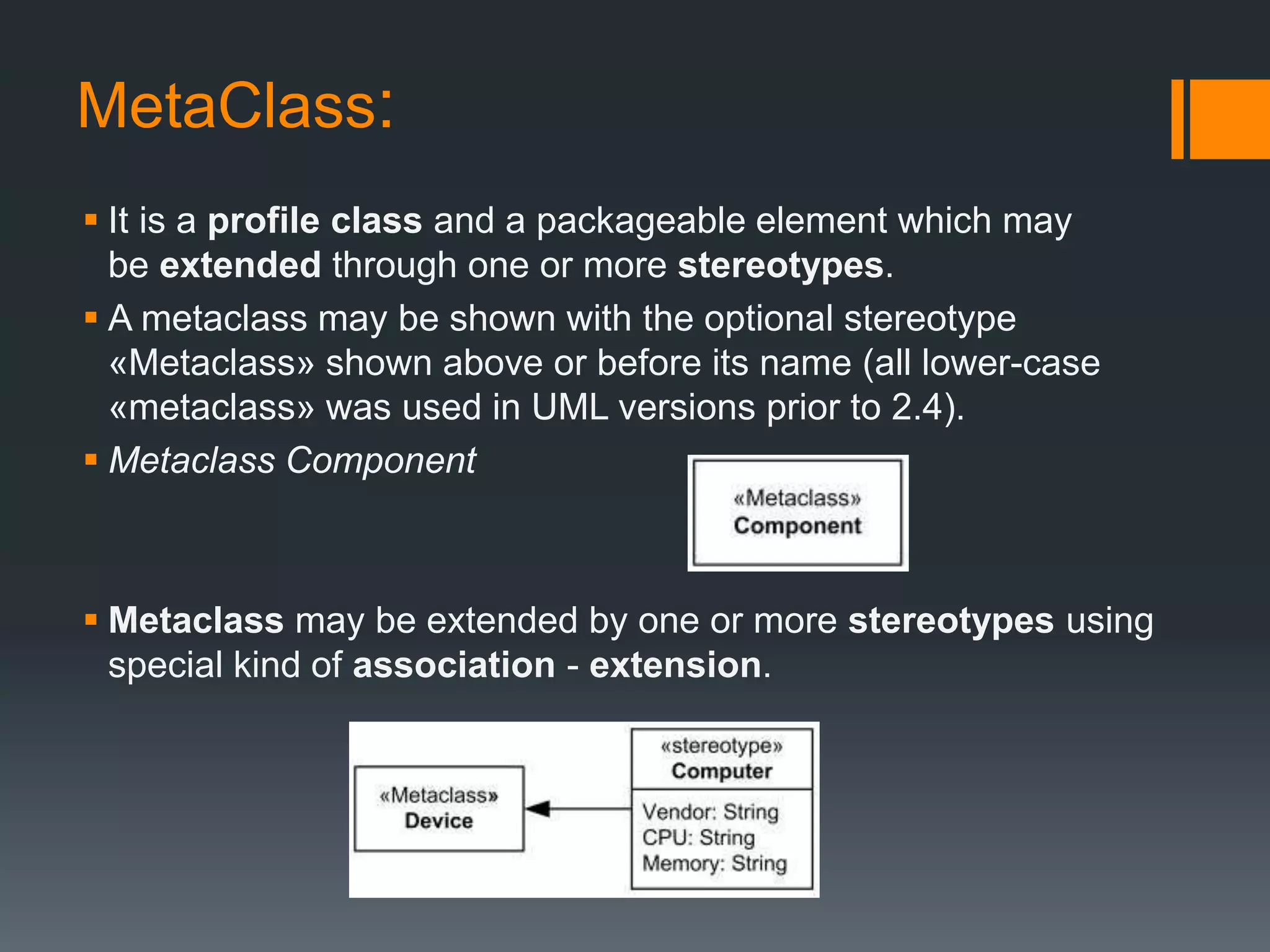
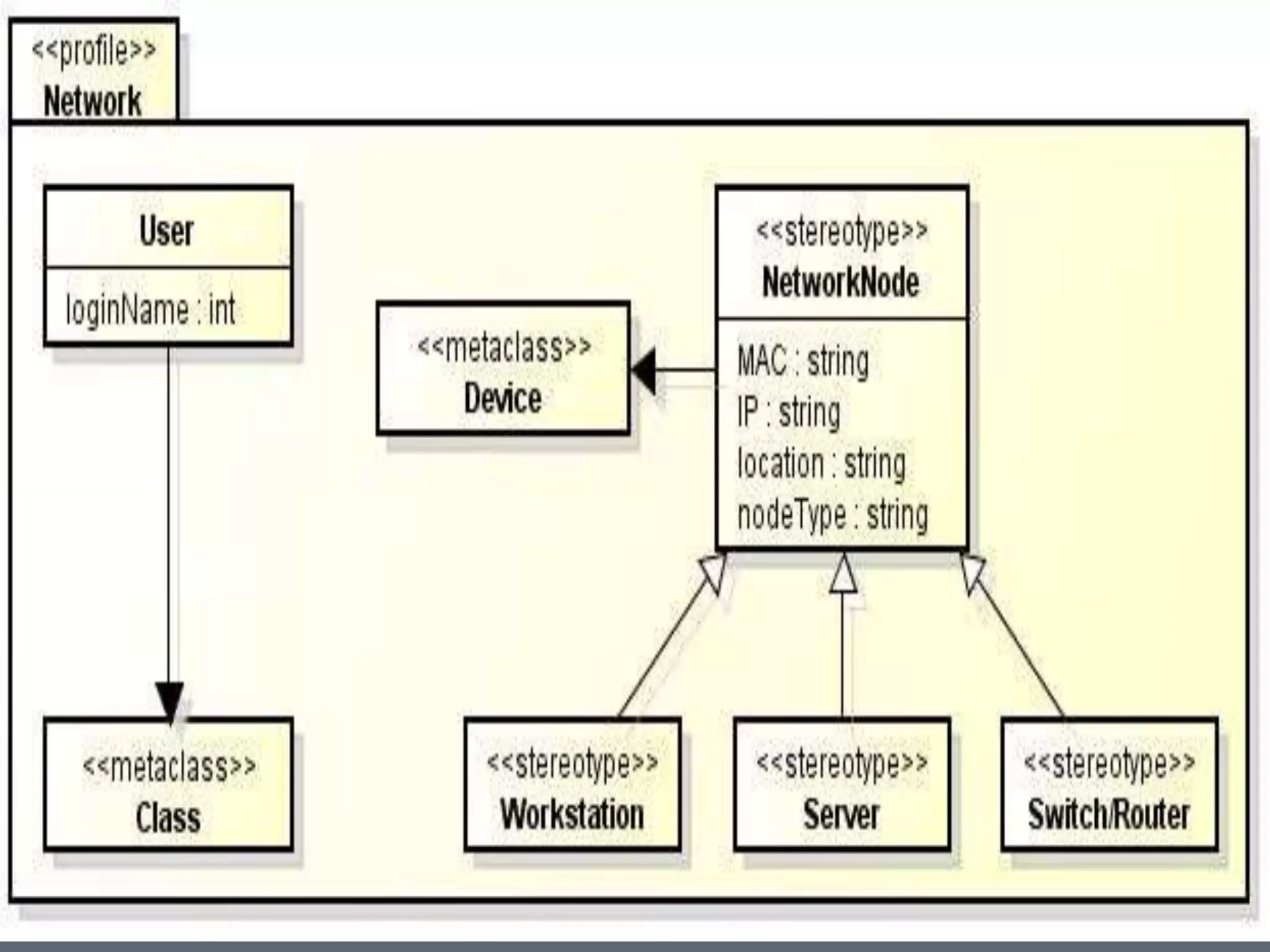
UML DIAGRAMS
Interaction Overview Diagram
&
Profile Diagram
By:
Husnain Safdar
BSSE-S15-08
UOS M.B.Din campus
Interaction Overview Diagram:
 The Interaction Overview Diagram focuses on the overview of
the flow of control of the interactions.
 The interaction overview diagram is similar to the activity
diagram, in that both visualize a sequence of activities.
 The difference is that, for an interaction overview, each
individual activity is pictured as a frame which can contain a
nested interaction diagram.
 This makes the interaction overview diagram useful to
"deconstruct a complex scenario that would otherwise require
multiple if-then-else paths to be illustrated as a single sequence
diagram"
Notations in Interaction Diagram:
Initial Node:
An initial node is a control node at which flow starts
when the activity is invoked. An activity may have more than one
initial node.
Activity Final Node:
An activity may have more than one activity final
node. The first one reached stops all flows in the activity.
Control Flow:
A control flow is an edge that starts an activity node
after the previous one is finished.
.
Constraint:
A condition or restriction expressed in natural
language text or in a machine readable language for the
purpose of declaring some of the semantics of an element.
The condition that must be true when evaluated in order for the
constraint to be satisfied.
Decision Node:
A decision node accepts tokens on an incoming
edge and presents them to multiple outgoing edges. Which of
the edges is actually traversed depends on the evaluation of
the guards on the outgoing edges.
Merge Node:
A merge node is a control node that brings together multiple
alternate flows. . A merge node has multiple incoming edges
and a single outgoing edge.
.
Fork Node:
A fork node is a control node that splits a flow into
multiple concurrent flows. A fork node has one incoming edge
and multiple outgoing edges.
Interaction:
An interaction is a unit of behavior that focuses on
the observable exchange of information between Connectable
Elements.
Interaction Use:
The InteractionUse is a shorthand for copying the
contents of the referred Interaction where the InteractionUse
is. It is common to want to share portions of an interaction
between several other interactions. An InteractionUse allows
multiple interactions to reference an interaction that represents
a common portion of their specification.
.
Profile diagram:
 Profile diagram is basically an extensibility mechanism that allows
you to extend and customize UML by adding new building blocks,
creating new properties and specifying new semantics in order to
make the language suitable to your specific problem domain.
 A profile is essentially a kind of package, and as you might expect it
uses the same notation as a package. The keyword «profile» is used,
either above or in front of the package name, to indicate that the
package is a profile.
 Profile diagram has three types of extensibility mechanisms:
 Stereotypes
 Tagged Values
 Constraints
Stereotypes:
 Stereotypes allow you to increase vocabulary of UML. You can
add, create new model elements, derived from existing ones but
that have specific properties that are suitable to your problem
domain.
 Stereotypes are used to introduce new building blocks that speak
the language of your domain and look primitive. It allows you to
introduce new graphical symbols.
 For example: When modeling a network you might need to have
symbols for <<router>>, <<switches>>, <<hub>> etc. A stereotype
allows you to make these things appear as primitive.
Tagged Values:
 used to extend the properties of UML so that you can add additional
information in the specification of a model element.
 It allows you to specify keyword value pairs of a model where
keywords are the attributes. Tagged values are graphically rendered
as string enclose in brackets.
 For Example: Consider a release team responsible for assembling,
testing and deployment of a system. In such case it is necessary to
keep a track on version and test results of the main subsystem.
Tagged values are used to add such info.
 Tagged Value can be useful for adding properties to the model for
some useful purposes:
 Code generation
 Version control
 Configuration management
 Authorship
Constraints:
 They are the properties for specifying semantics or conditions that
must be held true at all the time.
 It allows you to extend the semantics of UML building block by
adding new protocols. Graphically a constraint is rendered as
string enclose in brackets placed near associated element.
 For example: In development of a real time system it is necessary
to adorn the model with some necessary information such as
response time.
 Constraints can be on attributes, derived attributes and
associations. It can be attached to one or more model elements
shown as a note as well.
MetaClass:
 It is a profile class and a packageable element which may
be extended through one or more stereotypes.
 A metaclass may be shown with the optional stereotype
«Metaclass» shown above or before its name (all lower-case
«metaclass» was used in UML versions prior to 2.4).
 Metaclass Component
 Metaclass may be extended by one or more stereotypes using
special kind of association - extension.
.
 .
Thank
You

Interaction overview and Profile UML Diagrams

  • 1.
    UML DIAGRAMS Interaction OverviewDiagram & Profile Diagram By: Husnain Safdar BSSE-S15-08 UOS M.B.Din campus
  • 2.
    Interaction Overview Diagram: The Interaction Overview Diagram focuses on the overview of the flow of control of the interactions.  The interaction overview diagram is similar to the activity diagram, in that both visualize a sequence of activities.  The difference is that, for an interaction overview, each individual activity is pictured as a frame which can contain a nested interaction diagram.  This makes the interaction overview diagram useful to "deconstruct a complex scenario that would otherwise require multiple if-then-else paths to be illustrated as a single sequence diagram"
  • 3.
    Notations in InteractionDiagram: Initial Node: An initial node is a control node at which flow starts when the activity is invoked. An activity may have more than one initial node. Activity Final Node: An activity may have more than one activity final node. The first one reached stops all flows in the activity. Control Flow: A control flow is an edge that starts an activity node after the previous one is finished.
  • 4.
    . Constraint: A condition orrestriction expressed in natural language text or in a machine readable language for the purpose of declaring some of the semantics of an element. The condition that must be true when evaluated in order for the constraint to be satisfied. Decision Node: A decision node accepts tokens on an incoming edge and presents them to multiple outgoing edges. Which of the edges is actually traversed depends on the evaluation of the guards on the outgoing edges. Merge Node: A merge node is a control node that brings together multiple alternate flows. . A merge node has multiple incoming edges and a single outgoing edge.
  • 5.
    . Fork Node: A forknode is a control node that splits a flow into multiple concurrent flows. A fork node has one incoming edge and multiple outgoing edges. Interaction: An interaction is a unit of behavior that focuses on the observable exchange of information between Connectable Elements. Interaction Use: The InteractionUse is a shorthand for copying the contents of the referred Interaction where the InteractionUse is. It is common to want to share portions of an interaction between several other interactions. An InteractionUse allows multiple interactions to reference an interaction that represents a common portion of their specification.
  • 6.
  • 7.
    Profile diagram:  Profilediagram is basically an extensibility mechanism that allows you to extend and customize UML by adding new building blocks, creating new properties and specifying new semantics in order to make the language suitable to your specific problem domain.  A profile is essentially a kind of package, and as you might expect it uses the same notation as a package. The keyword «profile» is used, either above or in front of the package name, to indicate that the package is a profile.  Profile diagram has three types of extensibility mechanisms:  Stereotypes  Tagged Values  Constraints
  • 8.
    Stereotypes:  Stereotypes allowyou to increase vocabulary of UML. You can add, create new model elements, derived from existing ones but that have specific properties that are suitable to your problem domain.  Stereotypes are used to introduce new building blocks that speak the language of your domain and look primitive. It allows you to introduce new graphical symbols.  For example: When modeling a network you might need to have symbols for <<router>>, <<switches>>, <<hub>> etc. A stereotype allows you to make these things appear as primitive.
  • 9.
    Tagged Values:  usedto extend the properties of UML so that you can add additional information in the specification of a model element.  It allows you to specify keyword value pairs of a model where keywords are the attributes. Tagged values are graphically rendered as string enclose in brackets.  For Example: Consider a release team responsible for assembling, testing and deployment of a system. In such case it is necessary to keep a track on version and test results of the main subsystem. Tagged values are used to add such info.  Tagged Value can be useful for adding properties to the model for some useful purposes:  Code generation  Version control  Configuration management  Authorship
  • 10.
    Constraints:  They arethe properties for specifying semantics or conditions that must be held true at all the time.  It allows you to extend the semantics of UML building block by adding new protocols. Graphically a constraint is rendered as string enclose in brackets placed near associated element.  For example: In development of a real time system it is necessary to adorn the model with some necessary information such as response time.  Constraints can be on attributes, derived attributes and associations. It can be attached to one or more model elements shown as a note as well.
  • 11.
    MetaClass:  It isa profile class and a packageable element which may be extended through one or more stereotypes.  A metaclass may be shown with the optional stereotype «Metaclass» shown above or before its name (all lower-case «metaclass» was used in UML versions prior to 2.4).  Metaclass Component  Metaclass may be extended by one or more stereotypes using special kind of association - extension.
  • 12.
  • 13.