Downloaded 261 times
![Sequence Diagram
:A :B :C
[ x>0 ] doM()
[ x<=0 doN()]
Conditional branch
:A :B
Loop
*dialDigit(d)
Object-Oriented Software Systems Engineering – Chapter 7 Slide 12](https://image.slidesharecdn.com/7-sequenceandcollaborationdiagrams-121220200729-phpapp01/75/7-sequence-and-collaboration-diagrams-12-2048.jpg)
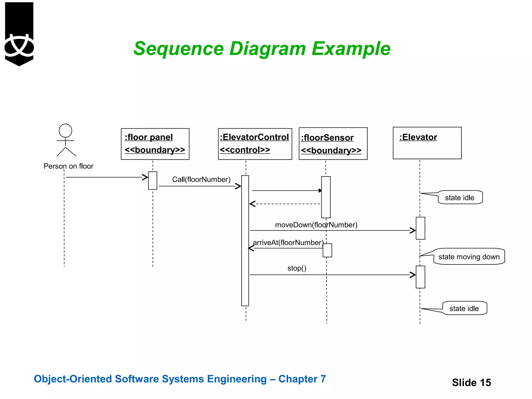
![Sequence Diagram Example
:ElevatorControl :floorSensor :Elevator
<<control>> <<boundary>>
state idle
[timer=time_out]/moveDown(firstfloor)
arriveAt(firstfloor)
state moving down to first floor
stop()
state on first floor
Object-Oriented Software Systems Engineering – Chapter 7 Slide 16](https://image.slidesharecdn.com/7-sequenceandcollaborationdiagrams-121220200729-phpapp01/75/7-sequence-and-collaboration-diagrams-16-2048.jpg)
![Collaboration Diagram for ElevatorControl
On further investigation ElevatorControl may
need to be expanded into more classes
revisit sequence diagrams!
:ElevatorControl
1: Call floor(number)
1.1: *[all queues]:len=length(){return shortest} 2: nextjob=get()
:Queue :Dispatcher
:Organiser
1.3:Invoke(job){join queue}
1.2:Create()
parameter
Active object
own thread
:Order of control
Object-Oriented Software Systems Engineering – Chapter 7 Slide 20](https://image.slidesharecdn.com/7-sequenceandcollaborationdiagrams-121220200729-phpapp01/75/7-sequence-and-collaboration-diagrams-20-2048.jpg)

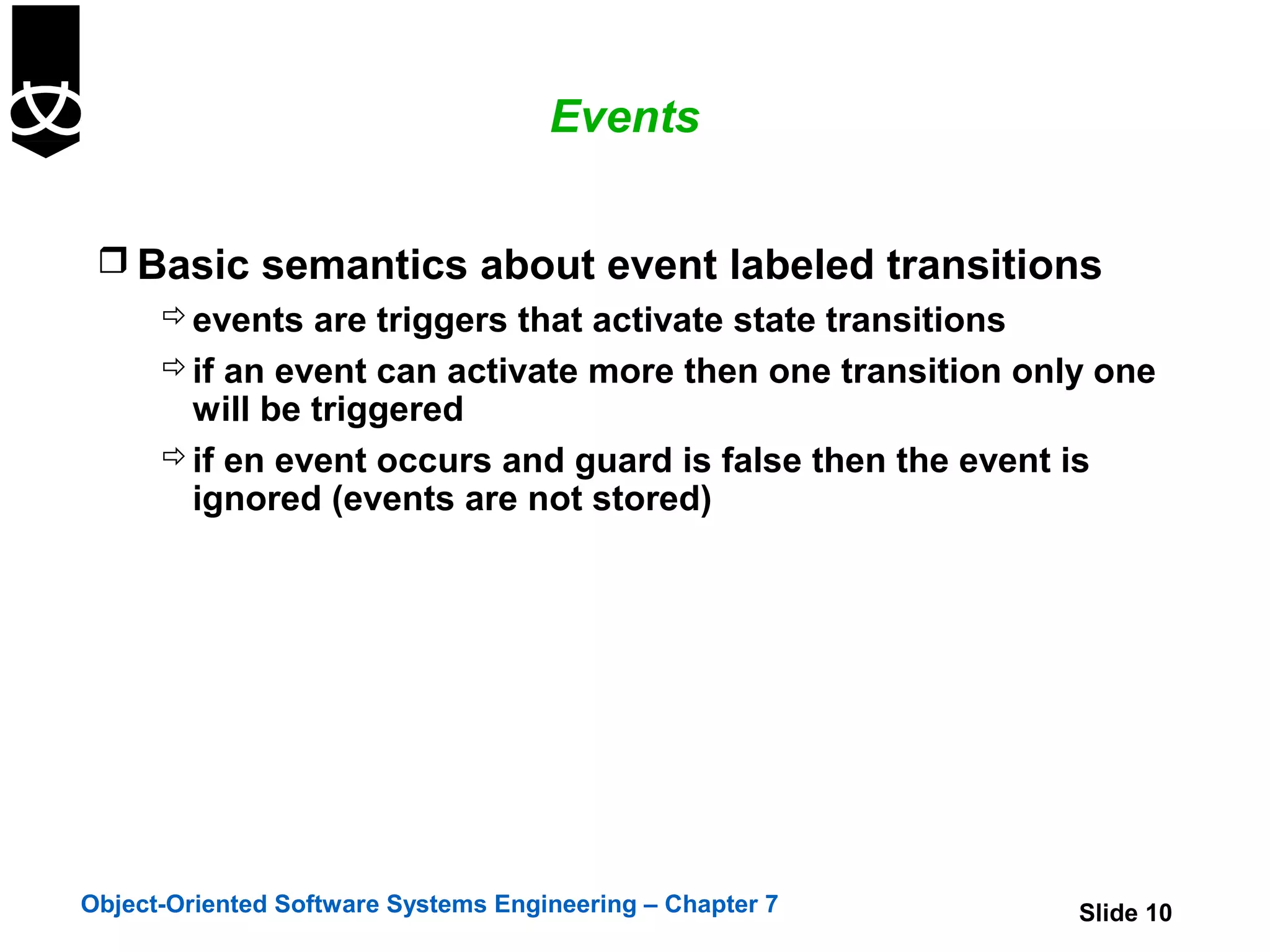
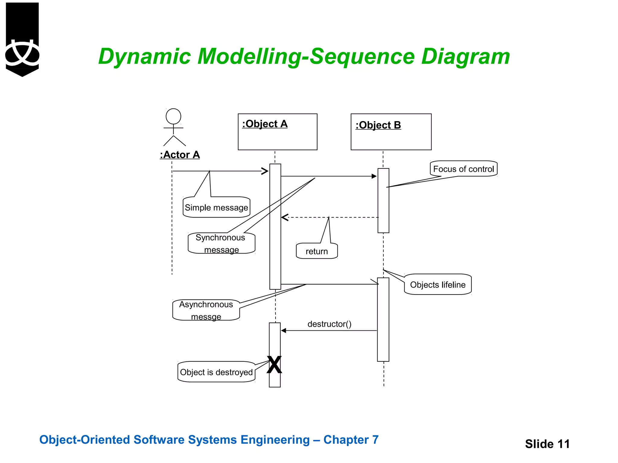
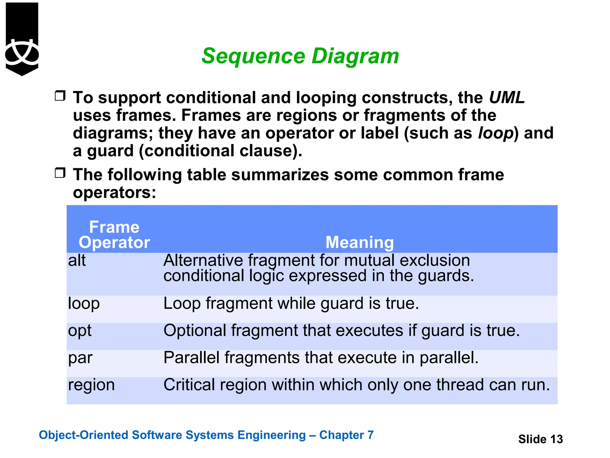
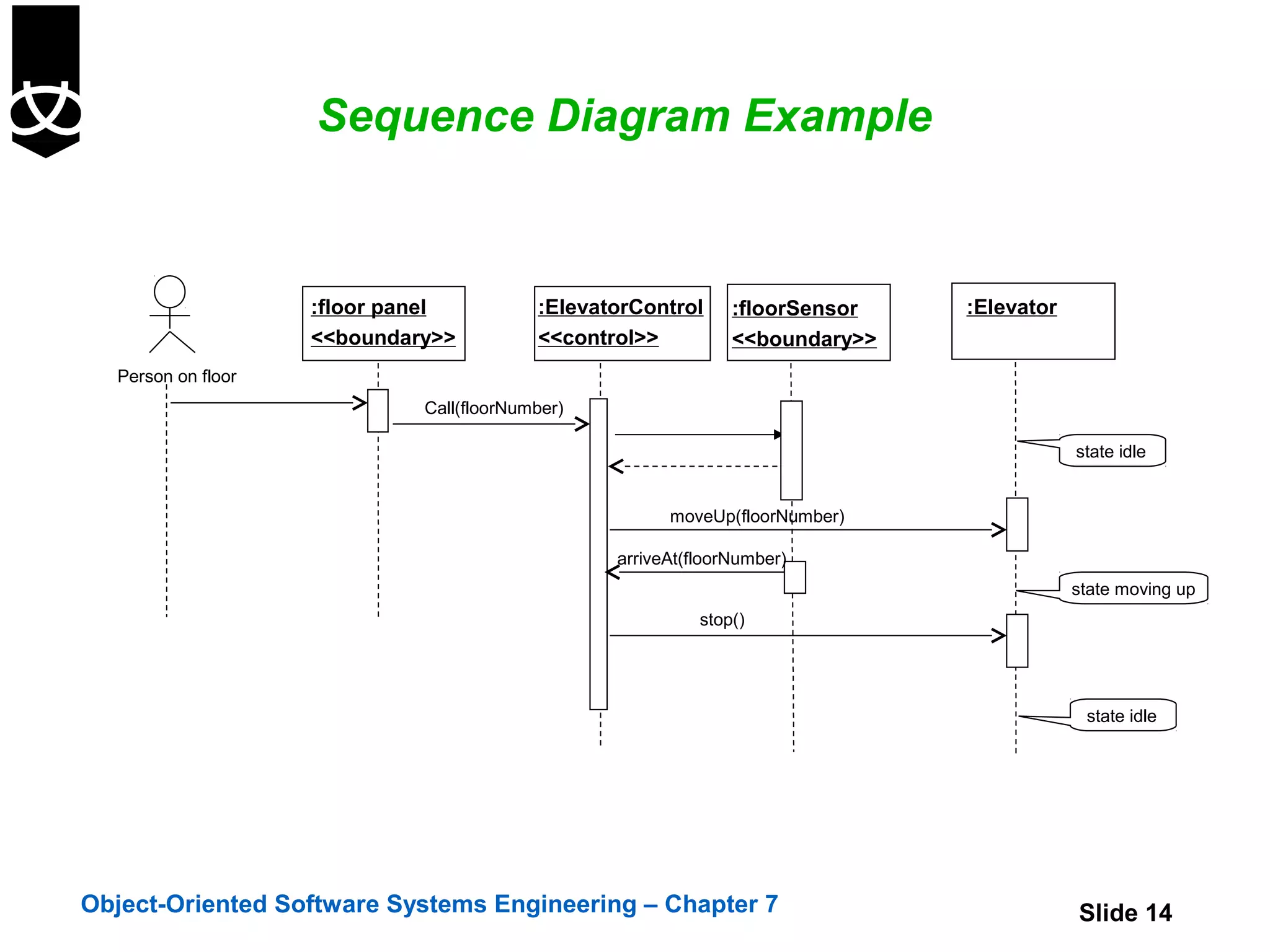
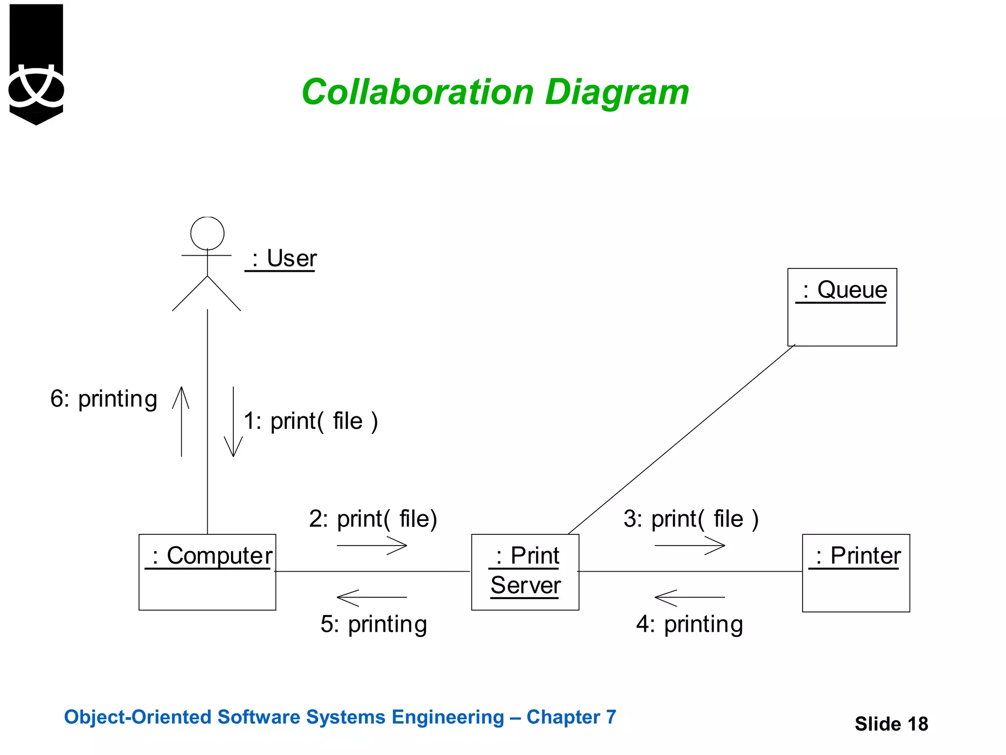
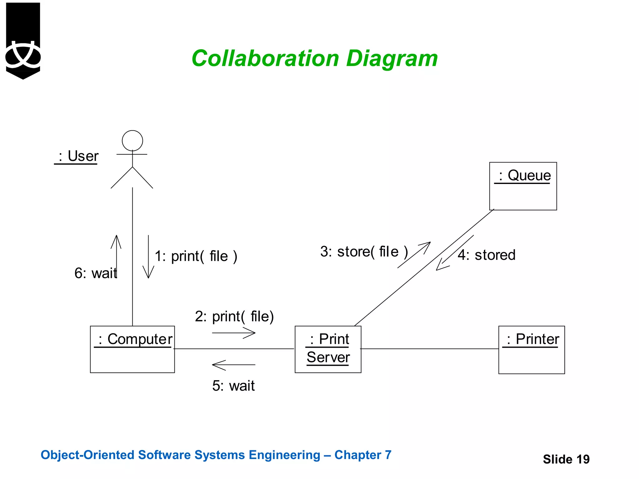
This chapter discusses dynamic modeling techniques used to describe the behavior of object-oriented systems. It introduces sequence diagrams and collaboration diagrams, which show how objects interact and communicate through messages. Sequence diagrams focus on the time-ordering of messages while collaboration diagrams emphasize the relationships between objects. The chapter also covers different types of messages and events that can be depicted in dynamic models.