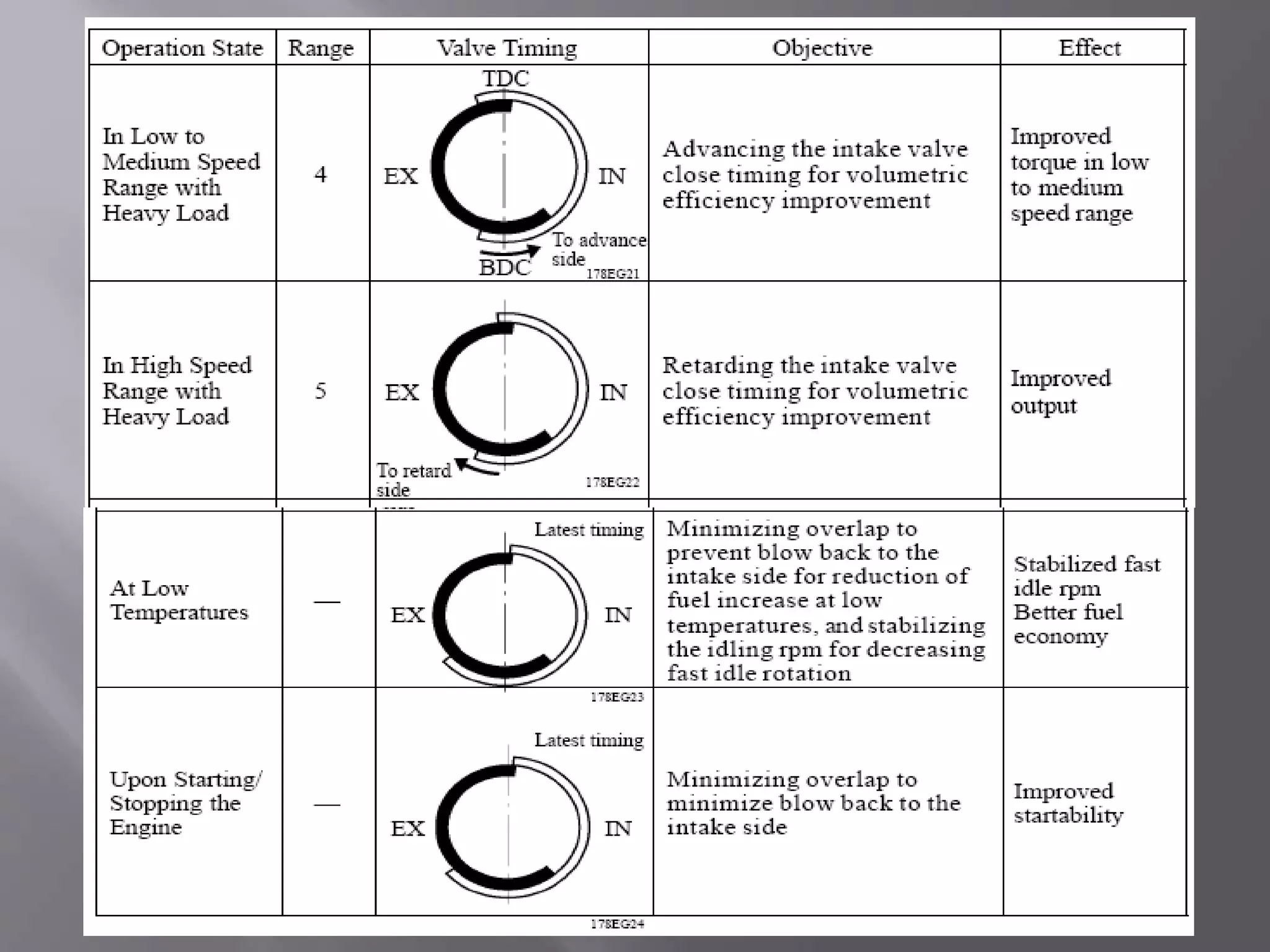
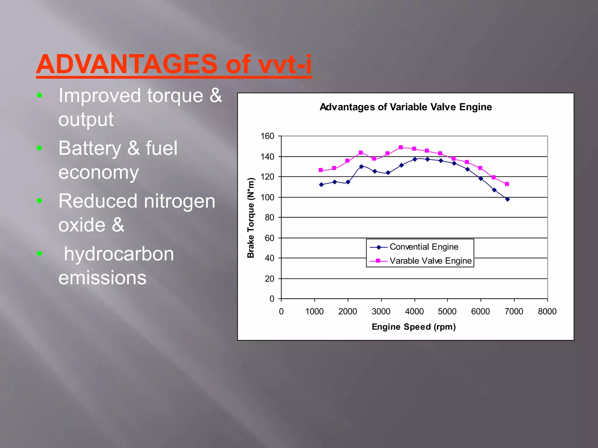
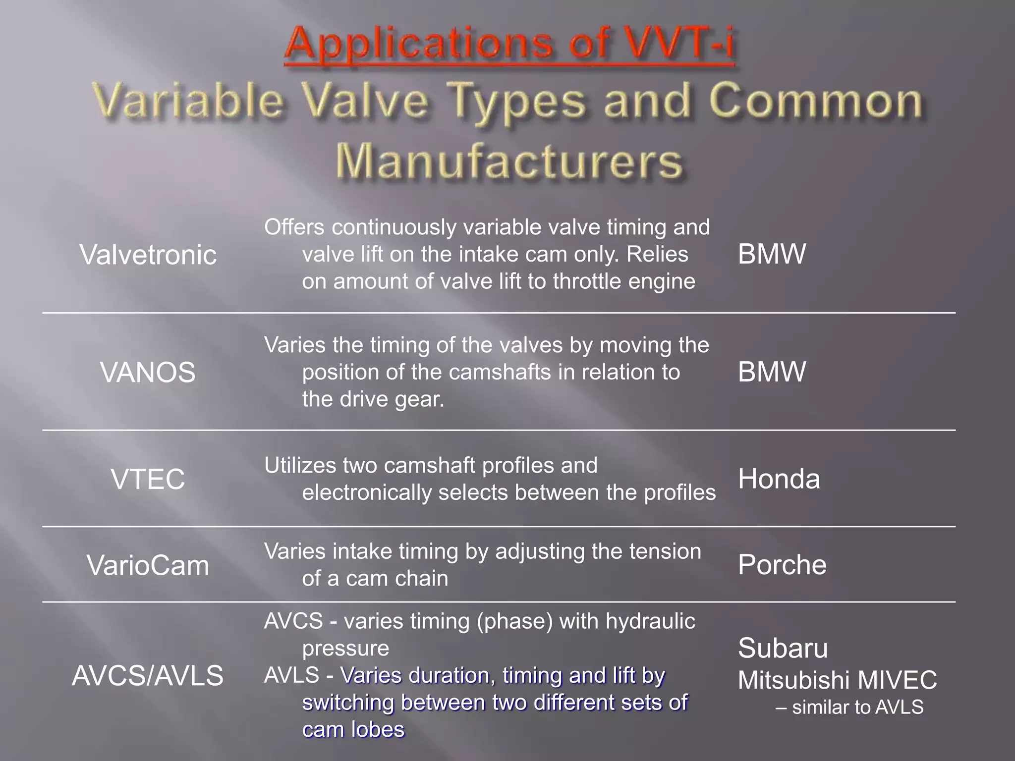
PRESENTED BY
UTSAV PODDAR
HRISIKESH BHASKAR
MAHIDUL HAQUE KHAMAR
 Basic Theory
After multivalve technology became standard in engine design,
Variable Valve Timing became the next step to enhance engine
output, power and torque. As you know, valves activate the
breathing of engine. The timing of breathing, that is, the timing of air
intake and exhaust, is controlled by the shape and phase angle of
cams. To optimise the breathing, engine requires different valve
timing at different speed. When the revolution increases, the duration
of intake and exhaust stroke decreases so that fresh air becomes not
fast enough to enter the combustion chamber, while the exhaust
becomes not fast enough to leave the combustion chamber. Therefore,
the best solution is to open the inlet valves earlier and close the
exhaust valves later. In other words, the Overlapping between intake
period and exhaust period should be increased as revolution
increases.
With Variable Valve Timing, power and torque can be optimised
across a wide rpm band.
 The VVT system is designed to control the intake
camshaft with in a range of 50°(of Crankshaft
Angle ) to provide valve timing i.e. optimally
suited to the engine condition .This improves the
torque in all the speed ranges as well as fuel
economy ,and reducing exhaust emissions
 This system controls the intake camshaft valve
timing so as to obtain balance between the engine
output, fuel consumption & emission control
performance. The actual intake side valve timing is
feed back by means of the camshaft position sensor
for constant control to the target valve timing
 There are two types of variable valve timing
A. Cam changing VVT
B. Cam phasing VVT
CAM CHANGING VVT
 Cam changing VVT uses different cam profiles to lift the valves depending on
engine load and speed.
 One common system uses two rocker arms for normal operation on its two
intake valves, with a third, higher profile, rocker arm between the other two
arms. At engine speeds above 5000 to 6000 rpm, the engine ECU activates an oil
pressure controlled pin that locks the three rocker arms together. The center
rocker arm follows a larger and more aggressive profile, transferring its
movement to the intake valves which now open further and for longer.
 When engine speeds fall below the threshold speed, oil pressure is removed
from the pin and a spring deactivates the pin. The rocker arms are no longer
locked together and the valves are controlled by the less aggressive outer lobes
 Stage 1 (low speed) : both intake and exhaust valves are in slow configuration.
 Stage 2 (medium speed) : fast intake configuration + slow exhaust
configuration.
 Stage 3 (high speed) : both intake and exhaust valves are in fast configuration.
 Advantage: Powerful at top end
 Disadvantage: 2 or 3 stages only, non-continuous; no much improvement to
torque; complex
 Who use it ? Honda VTEC, Mitsubishi MIVEC, Nissan Neo VVL.
CAM PHASING VVT
 Cam phasing VVT is the simplest, cheapest and most
commonly used mechanism at this moment.
 it varies the valve timing by shifting the phase angle of
camshafts. For example, at high speed, the inlet camshaft will
be rotated in advance by 30° so to enable earlier intake. This
movement is controlled by engine management system
according to need, and actuated by hydraulic valve gears
 IT cannot vary the duration of valve opening. It just allows
earlier or later valve opening. Earlier open results in earlier
close, of course. It also cannot vary the valve lift, unlike cam
changing VVT
 Advantage: Cheap and simple, continuous VVT improves
torque delivery across the whole rev range.
 Disadvantage: Lack of variable lift and variable valve opening
duration, thus less top end power than Camchanging VVT.
 Audi V8 inlet, BMW Double Vanos inlet,Ferrari 360 Modena
exhaust, Ford Puma 1.7 Zetec SE inlet, Jaguar AJV6,
Lamborghini Diablo SV engine inlet, , Porsche Variocam inlet,
3stage discrete
3) Cam-Changing + Cam- Phasing VVT
Combining camchanging VVT and camphasing
VVT could satisfy the requirement of both top
end Power and flexibility throughout the whole
rev range, but it is inevitably more complex. At
the time of writing, only Toyota and Porsche have
such designs.
 The Variable Valve Timing (VVT) system includes
 ECM
 OCV
 VVT controller
• The ECM sends a target duty-cycle control signal to the
OCV. This control signal regulates the oil pressure supplied
to the VVT controller. Camshaft timing control is performed
according to engine operating conditions such as the intake
air volume, throttle valve position and engine coolant
temperature.
• The ECM controls the OCV, based on the signals
transmitted by several sensors. The VVT controller
regulates the intake camshaft angle using oil pressure
through the OCV. As a result, the relative positions of the
camshaft and crankshaft are optimized, the engine torque
and fuel economy improve, and the exhaust emissions
decrease under overall driving conditions. The ECM detects
the actual intake valve timing using signals from the
camshaft and crankshaft position sensors, and performs
feedback control.
This is how the target intake valve timing is verified by the
ECM.
The ECM optimizes the valve timing using the VVT
system to control the intake camshaft. The VVT
system includes the ECM, the OCV and the VVT
controller. The ECM sends a target duty-cycle control
signal to the OCV. This control signal regulates the
oil pressure supplied to the VVT controller. The VVT
controller can advance or retard the intake camshaft.
The camshaft timing oil control valve selects the path according
to the advance, retard or hold signal from the ECM .The VVT-i
controller rotates the intake camshaft in the timing advance or
retard position or holds it according to the position where the oil
pressure is applied.
In proportion to the engine speed, intake air volume throttle position and
water temperature, the ECM calculates optimal valve timing under each
driving condition & controls the camshaft timing oil control valve. In addition
ECM uses signal from the camshaft position sensor & the crankshaft position
sensor to detect the actual valve timing, thus performing feedback control to
achieve the target valve timing
ADVANTAGES of vvt-i
• Improved torque &
output
• Battery & fuel
economy
• Reduced nitrogen
oxide &
• hydrocarbon
emissions
Advantages of Variable Valve Engine
0
20
40
60
80
100
120
140
160
0 1000 2000 3000 4000 5000 6000 7000 8000
Engine Speed (rpm)
BrakeTorque(N*m) Convential Engine
Varable Valve Engine
Valvetronic
Offers continuously variable valve timing and
valve lift on the intake cam only. Relies
on amount of valve lift to throttle engine
BMW
VANOS
Varies the timing of the valves by moving the
position of the camshafts in relation to
the drive gear.
BMW
VTEC
Utilizes two camshaft profiles and
electronically selects between the profiles
Honda
VarioCam
Varies intake timing by adjusting the tension
of a cam chain
Porche
AVCS/AVLS
AVCS - varies timing (phase) with hydraulic
pressure
AVLS - Varies duration, timing and lift by
switching between two different sets of
cam lobes
Subaru
Mitsubishi MIVEC
– similar to AVLS
Last but not the least, a special word of
thanks to the teachers and staff for their ever
ready help and guidance without which this
task would not be possible:
Prof. Amitava Datta
•Different Types of VVT. 2005. 3 May 2007.
http://www.autozine.org/technical_school/engine/vvt_2.htm
 Wikipedia: Variable Valve Timing. 2007. 1 May 2007.
<http://en.wikipedia.org/wiki/Variable_valve_timing
 Honda Engines. 2007. 2 May 2007.<http://www.honda-engines-
eu.com/en/images/249.gif >
 Prof. Dr. Peter Walzer. Technology Highlights and R and D
Activities. 2002
http://www.fev.com/data/documents/spectrum20.pdf
Variable Valve Timing

Variable Valve Timing

  • 1.
    PRESENTED BY UTSAV PODDAR HRISIKESHBHASKAR MAHIDUL HAQUE KHAMAR
  • 2.
     Basic Theory Aftermultivalve technology became standard in engine design, Variable Valve Timing became the next step to enhance engine output, power and torque. As you know, valves activate the breathing of engine. The timing of breathing, that is, the timing of air intake and exhaust, is controlled by the shape and phase angle of cams. To optimise the breathing, engine requires different valve timing at different speed. When the revolution increases, the duration of intake and exhaust stroke decreases so that fresh air becomes not fast enough to enter the combustion chamber, while the exhaust becomes not fast enough to leave the combustion chamber. Therefore, the best solution is to open the inlet valves earlier and close the exhaust valves later. In other words, the Overlapping between intake period and exhaust period should be increased as revolution increases. With Variable Valve Timing, power and torque can be optimised across a wide rpm band.
  • 3.
     The VVTsystem is designed to control the intake camshaft with in a range of 50°(of Crankshaft Angle ) to provide valve timing i.e. optimally suited to the engine condition .This improves the torque in all the speed ranges as well as fuel economy ,and reducing exhaust emissions  This system controls the intake camshaft valve timing so as to obtain balance between the engine output, fuel consumption & emission control performance. The actual intake side valve timing is feed back by means of the camshaft position sensor for constant control to the target valve timing
  • 4.
     There aretwo types of variable valve timing A. Cam changing VVT B. Cam phasing VVT CAM CHANGING VVT  Cam changing VVT uses different cam profiles to lift the valves depending on engine load and speed.  One common system uses two rocker arms for normal operation on its two intake valves, with a third, higher profile, rocker arm between the other two arms. At engine speeds above 5000 to 6000 rpm, the engine ECU activates an oil pressure controlled pin that locks the three rocker arms together. The center rocker arm follows a larger and more aggressive profile, transferring its movement to the intake valves which now open further and for longer.  When engine speeds fall below the threshold speed, oil pressure is removed from the pin and a spring deactivates the pin. The rocker arms are no longer locked together and the valves are controlled by the less aggressive outer lobes  Stage 1 (low speed) : both intake and exhaust valves are in slow configuration.  Stage 2 (medium speed) : fast intake configuration + slow exhaust configuration.  Stage 3 (high speed) : both intake and exhaust valves are in fast configuration.  Advantage: Powerful at top end  Disadvantage: 2 or 3 stages only, non-continuous; no much improvement to torque; complex  Who use it ? Honda VTEC, Mitsubishi MIVEC, Nissan Neo VVL.
  • 6.
    CAM PHASING VVT Cam phasing VVT is the simplest, cheapest and most commonly used mechanism at this moment.  it varies the valve timing by shifting the phase angle of camshafts. For example, at high speed, the inlet camshaft will be rotated in advance by 30° so to enable earlier intake. This movement is controlled by engine management system according to need, and actuated by hydraulic valve gears  IT cannot vary the duration of valve opening. It just allows earlier or later valve opening. Earlier open results in earlier close, of course. It also cannot vary the valve lift, unlike cam changing VVT  Advantage: Cheap and simple, continuous VVT improves torque delivery across the whole rev range.  Disadvantage: Lack of variable lift and variable valve opening duration, thus less top end power than Camchanging VVT.  Audi V8 inlet, BMW Double Vanos inlet,Ferrari 360 Modena exhaust, Ford Puma 1.7 Zetec SE inlet, Jaguar AJV6, Lamborghini Diablo SV engine inlet, , Porsche Variocam inlet, 3stage discrete
  • 8.
    3) Cam-Changing +Cam- Phasing VVT Combining camchanging VVT and camphasing VVT could satisfy the requirement of both top end Power and flexibility throughout the whole rev range, but it is inevitably more complex. At the time of writing, only Toyota and Porsche have such designs.
  • 9.
     The VariableValve Timing (VVT) system includes  ECM  OCV  VVT controller • The ECM sends a target duty-cycle control signal to the OCV. This control signal regulates the oil pressure supplied to the VVT controller. Camshaft timing control is performed according to engine operating conditions such as the intake air volume, throttle valve position and engine coolant temperature. • The ECM controls the OCV, based on the signals transmitted by several sensors. The VVT controller regulates the intake camshaft angle using oil pressure through the OCV. As a result, the relative positions of the camshaft and crankshaft are optimized, the engine torque and fuel economy improve, and the exhaust emissions decrease under overall driving conditions. The ECM detects the actual intake valve timing using signals from the camshaft and crankshaft position sensors, and performs feedback control. This is how the target intake valve timing is verified by the ECM.
  • 11.
    The ECM optimizesthe valve timing using the VVT system to control the intake camshaft. The VVT system includes the ECM, the OCV and the VVT controller. The ECM sends a target duty-cycle control signal to the OCV. This control signal regulates the oil pressure supplied to the VVT controller. The VVT controller can advance or retard the intake camshaft.
  • 13.
    The camshaft timingoil control valve selects the path according to the advance, retard or hold signal from the ECM .The VVT-i controller rotates the intake camshaft in the timing advance or retard position or holds it according to the position where the oil pressure is applied.
  • 14.
    In proportion tothe engine speed, intake air volume throttle position and water temperature, the ECM calculates optimal valve timing under each driving condition & controls the camshaft timing oil control valve. In addition ECM uses signal from the camshaft position sensor & the crankshaft position sensor to detect the actual valve timing, thus performing feedback control to achieve the target valve timing
  • 17.
    ADVANTAGES of vvt-i •Improved torque & output • Battery & fuel economy • Reduced nitrogen oxide & • hydrocarbon emissions Advantages of Variable Valve Engine 0 20 40 60 80 100 120 140 160 0 1000 2000 3000 4000 5000 6000 7000 8000 Engine Speed (rpm) BrakeTorque(N*m) Convential Engine Varable Valve Engine
  • 18.
    Valvetronic Offers continuously variablevalve timing and valve lift on the intake cam only. Relies on amount of valve lift to throttle engine BMW VANOS Varies the timing of the valves by moving the position of the camshafts in relation to the drive gear. BMW VTEC Utilizes two camshaft profiles and electronically selects between the profiles Honda VarioCam Varies intake timing by adjusting the tension of a cam chain Porche AVCS/AVLS AVCS - varies timing (phase) with hydraulic pressure AVLS - Varies duration, timing and lift by switching between two different sets of cam lobes Subaru Mitsubishi MIVEC – similar to AVLS
  • 19.
    Last but notthe least, a special word of thanks to the teachers and staff for their ever ready help and guidance without which this task would not be possible: Prof. Amitava Datta
  • 20.
    •Different Types ofVVT. 2005. 3 May 2007. http://www.autozine.org/technical_school/engine/vvt_2.htm  Wikipedia: Variable Valve Timing. 2007. 1 May 2007. <http://en.wikipedia.org/wiki/Variable_valve_timing  Honda Engines. 2007. 2 May 2007.<http://www.honda-engines- eu.com/en/images/249.gif >  Prof. Dr. Peter Walzer. Technology Highlights and R and D Activities. 2002 http://www.fev.com/data/documents/spectrum20.pdf