• An interactionis a behavior that comprises a set of
messages exchanged among a set of objects within a
context to accomplish a purpose
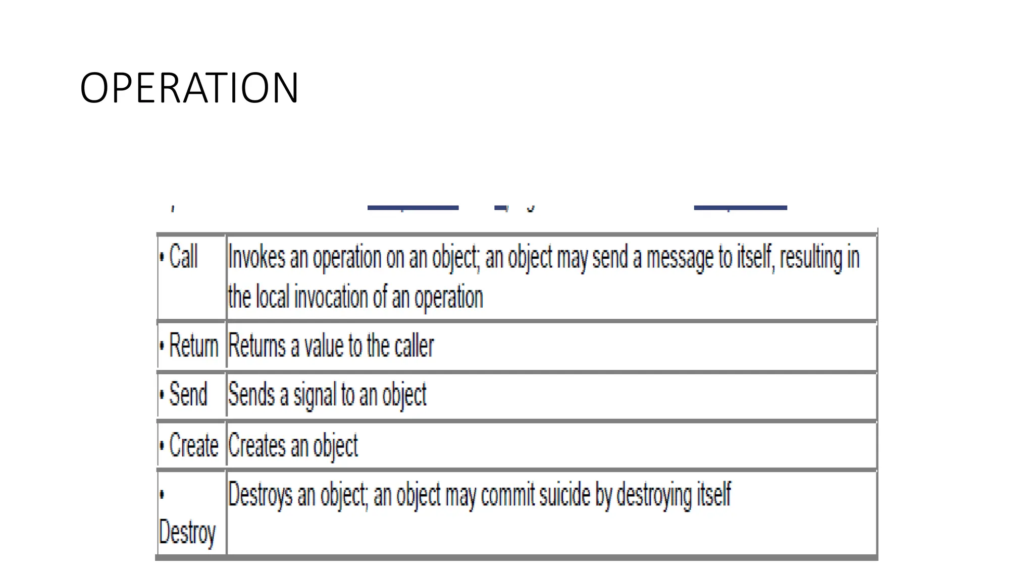
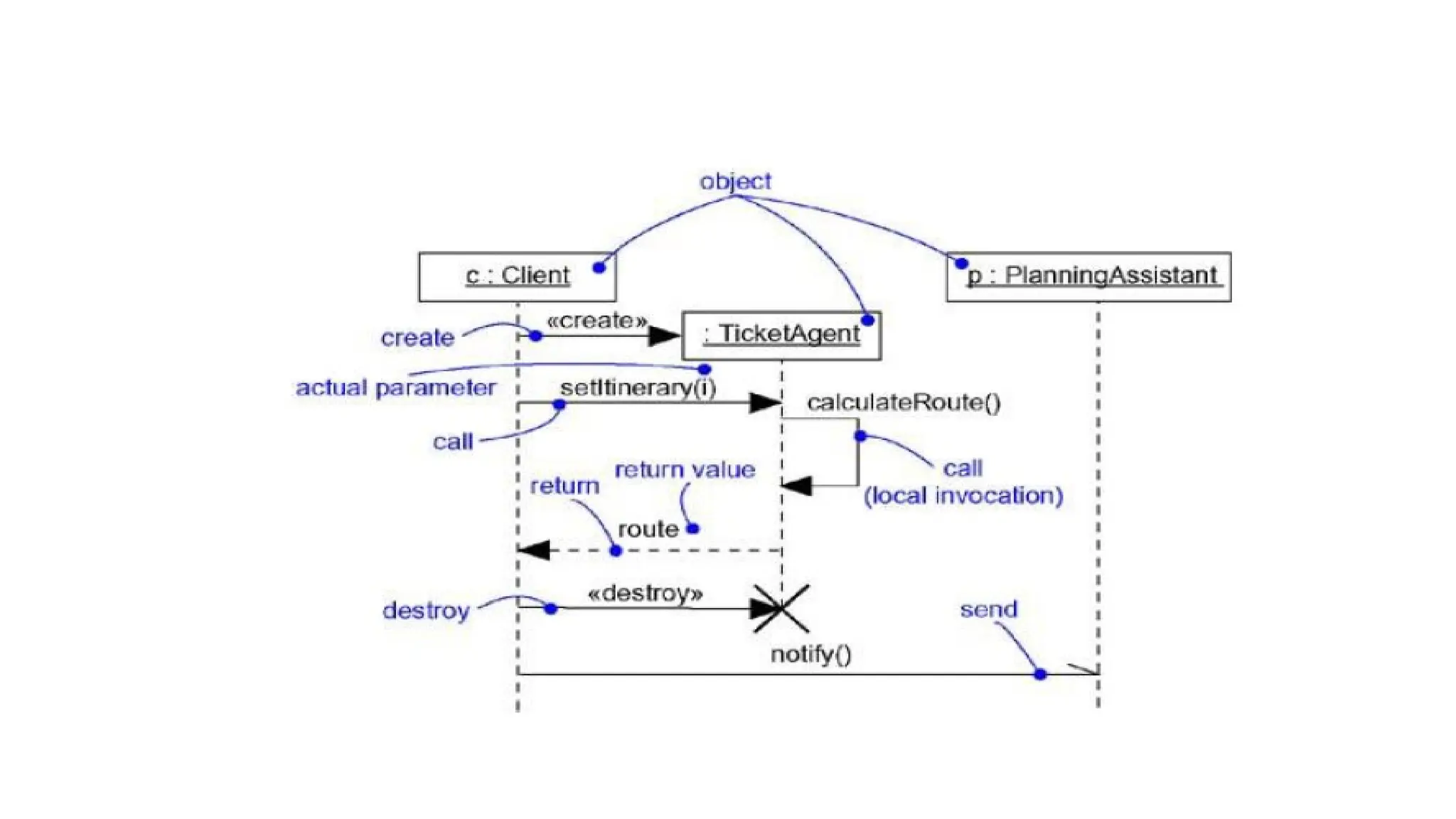
•A message is a specification of a communication
between objects that conveys information with the
expectation that activity will ensue
3.
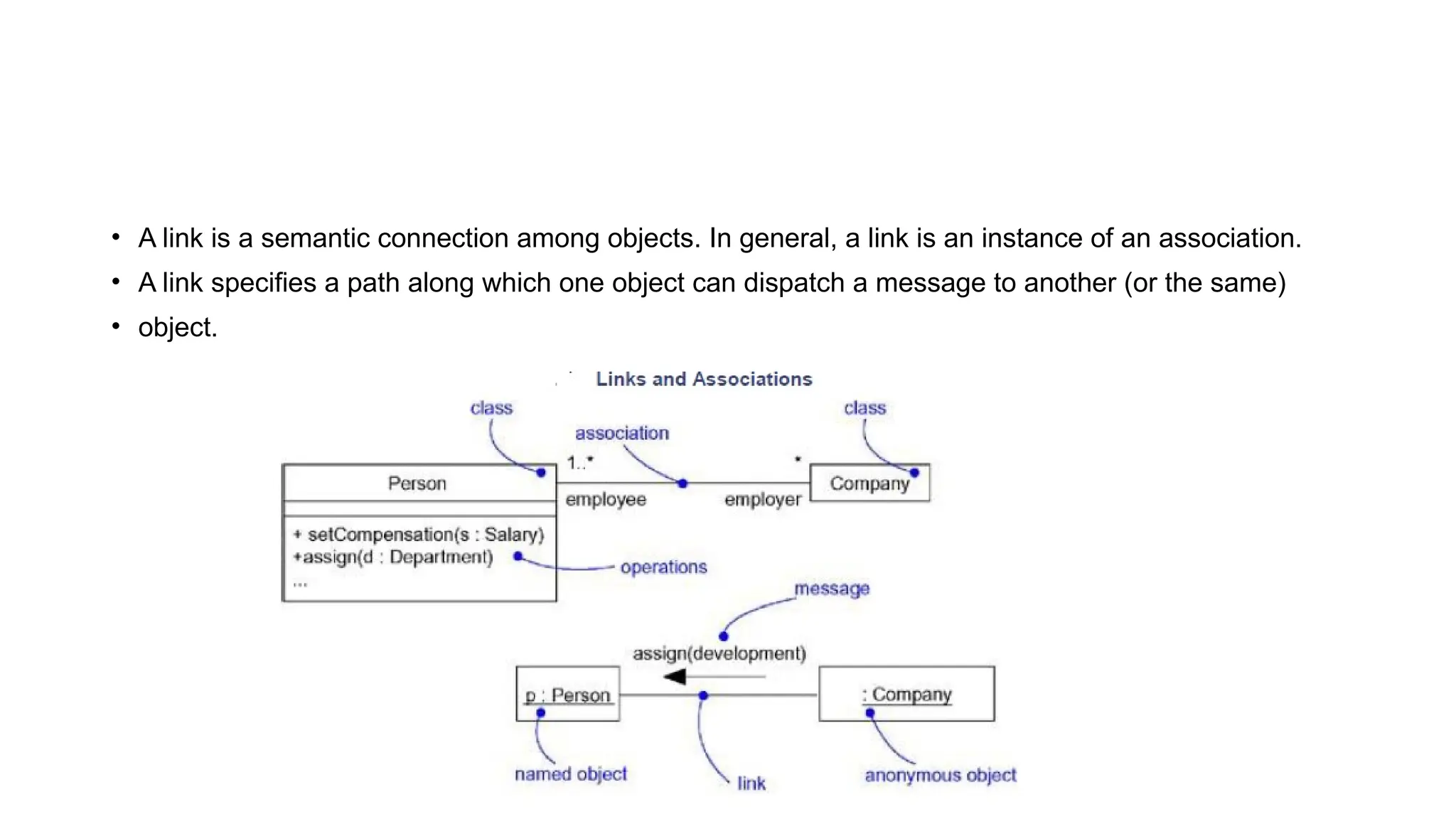
• A linkis a semantic connection among objects. In general, a link is an instance of an association.
• A link specifies a path along which one object can dispatch a message to another (or the same)
• object.
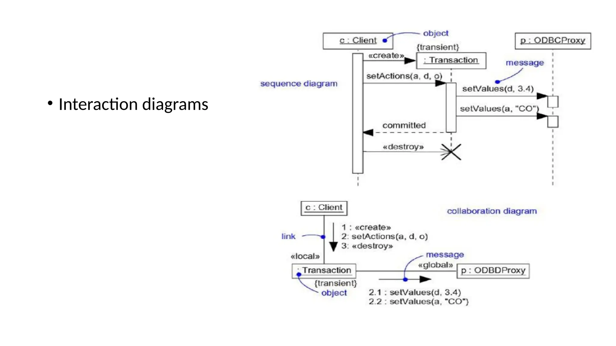
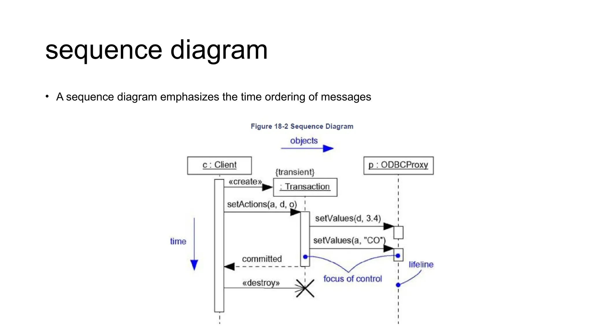
• A sequencediagram is an interaction diagram that emphasizes the time ordering of messages
• A collaboration diagram is an interaction diagram that emphasizes the structural organization of the
objects that send and receive messages. Graphically, a collaboration diagram is a collection of
vertices and arcs.
Sequence Diagrams
Sequence Diagrams
• First, thereis the object lifeline. An object lifeline is the vertical dashed line that represents the
existence of an object over a period of time.
• Second, there is the focus of control. The focus of control is a tall, thin rectangle that shows the
period of time during which an object is performing an action, either directly or through a
subordinate procedure.
12.
collaboration diagram
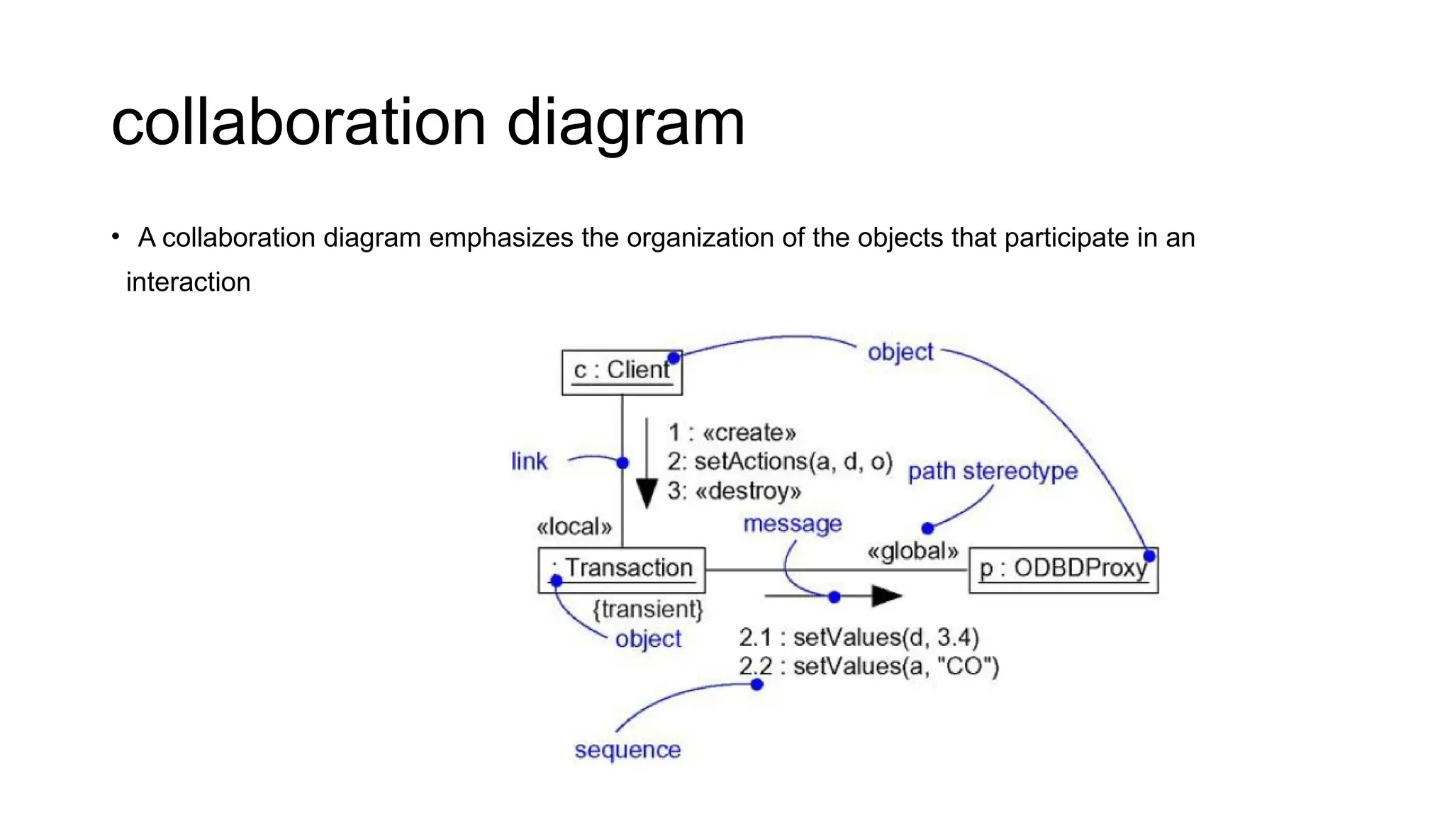
• Acollaboration diagram emphasizes the organization of the objects that participate in an
interaction
13.
Collaboration diagrams havetwo features that distinguish them from sequence diagrams
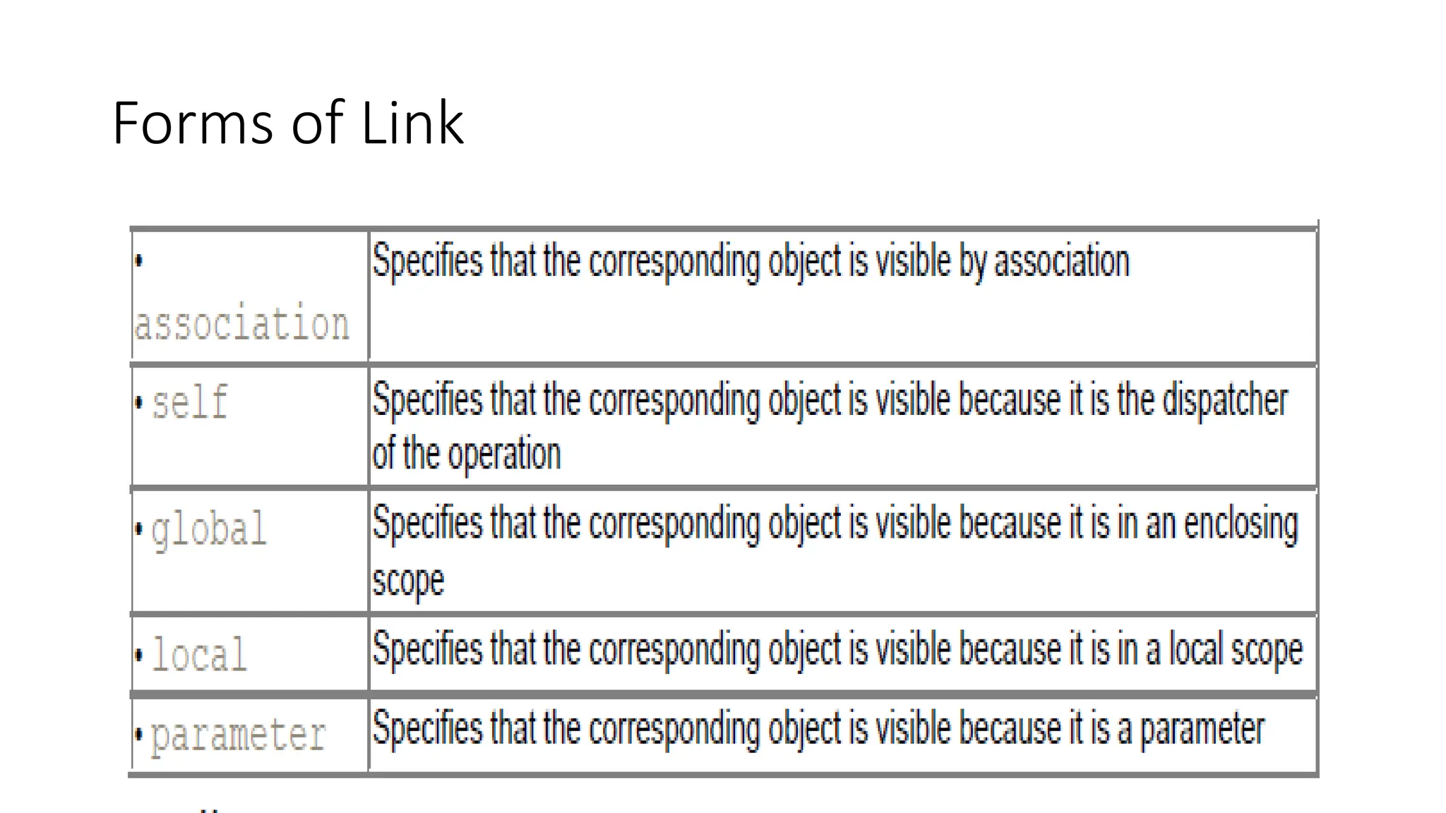
• First, there is the path. To indicate how one object is linked to another, you can attach a path
stereotype to the far end of a link (such as »localᑺ, indicating that the designated object is local to
the sender). Typically, you will only need to render the path of the link explicitly for
local,parameter, global, and self (but not association) paths
• Second, there is the sequence number. To indicate the time order of a message, you prefix the
message with a number (starting with the message numbered 1), increasing monotonically for each
new message in the flow of control (2, 3, and so on). To show nesting, you use Dewey decimal
numbering (1 is the first message; 1.1 is the first message nested in message 1; 1.2 is the
second message nested in message 1; and so on).
• A usecase is a description of a set of sequences of actions, including variants, that
a system performs to yield an observable result of value to an actor. Graphically, a
use case is rendered as an ellipse.
• An actor represents a coherent set of roles that users of use cases play when
interacting with these use cases. Typically, an actor represents a role that a human,
a hardware device, or even another system plays with a system.
• Actors may be connected to use cases only by association. An association between
an actor and a use case indicates that the actor and the use case communicate with
one another, each one possibly sending and receiving messages.
16.
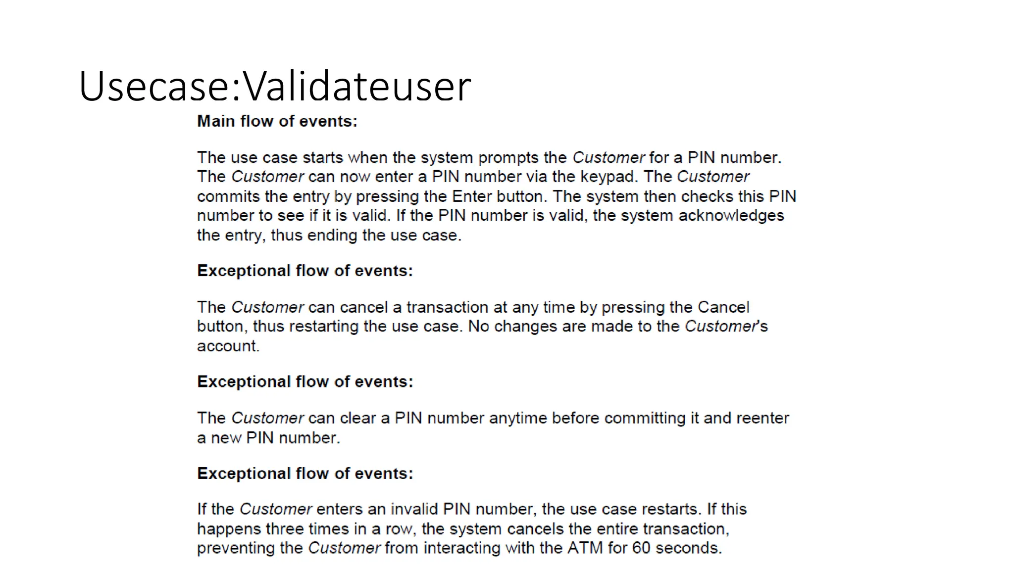
• You canspecify the behavior of a use case by describing a flow of events in text
clearly enough for an outsider to understand it easily. When you write this flow
of events, you should include how and when the use case starts and ends, when
the use case interacts with the actors and what objects are exchanged, and the
basic flow and alternative flows of the behavior.
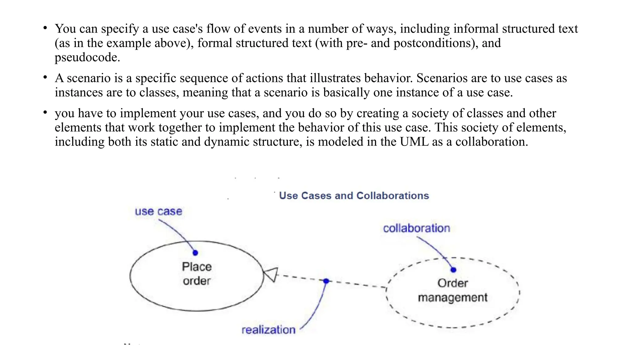
• You canspecify a use case's flow of events in a number of ways, including informal structured text
(as in the example above), formal structured text (with pre- and postconditions), and
pseudocode.
• A scenario is a specific sequence of actions that illustrates behavior. Scenarios are to use cases as
instances are to classes, meaning that a scenario is basically one instance of a use case.
• you have to implement your use cases, and you do so by creating a society of classes and other
elements that work together to implement the behavior of this use case. This society of elements,
including both its static and dynamic structure, is modeled in the UML as a collaboration.
19.
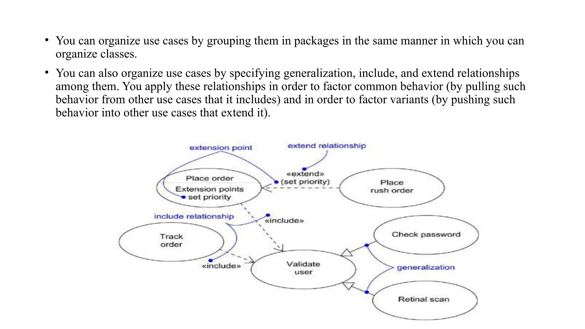
• You canorganize use cases by grouping them in packages in the same manner in which you can
organize classes.
• You can also organize use cases by specifying generalization, include, and extend relationships
among them. You apply these relationships in order to factor common behavior (by pulling such
behavior from other use cases that it includes) and in order to factor variants (by pushing such
behavior into other use cases that extend it).
20.
Use cases areclassifiers,
• Use cases are classifiers, so they may have attributes and operations that you may render just as
for classes. You can think of these attributes as the objects inside the use case that you need to
describe its outside behavior. Similarly, you can think of these operations as the actions of the
system you need to describe a flow of events. These objects and operations may be used in your
interaction diagrams to specify the behavior of the use case.
• As classifiers, you can also attach state machines to use cases. You can use state machines as
yet another way to describe the behavior represented by a use case.
21.
Use case diagrams
•Use case diagrams are one of the five diagrams in the UML for modeling the dynamic aspects of
systems (activity diagrams, statechart diagrams, sequence diagrams, and collaboration diagrams
are four other kinds of diagrams in the UML for modeling the dynamic aspects of systems). Use
case diagrams are central to modeling the behavior of a system, a subsystem, or a class. Each
one shows a set of use cases and actors and their relationships.
• You apply use case diagrams to model the use case view of a system. For the most part, this
involves modeling the context of a system, subsystem, or class, or modeling the requirements of the
behavior of these elements.
22.
Use case diagramscommonly contain
• Use cases
• Actors
• Dependency, generalization, and association relationships
23.
Use case diagram
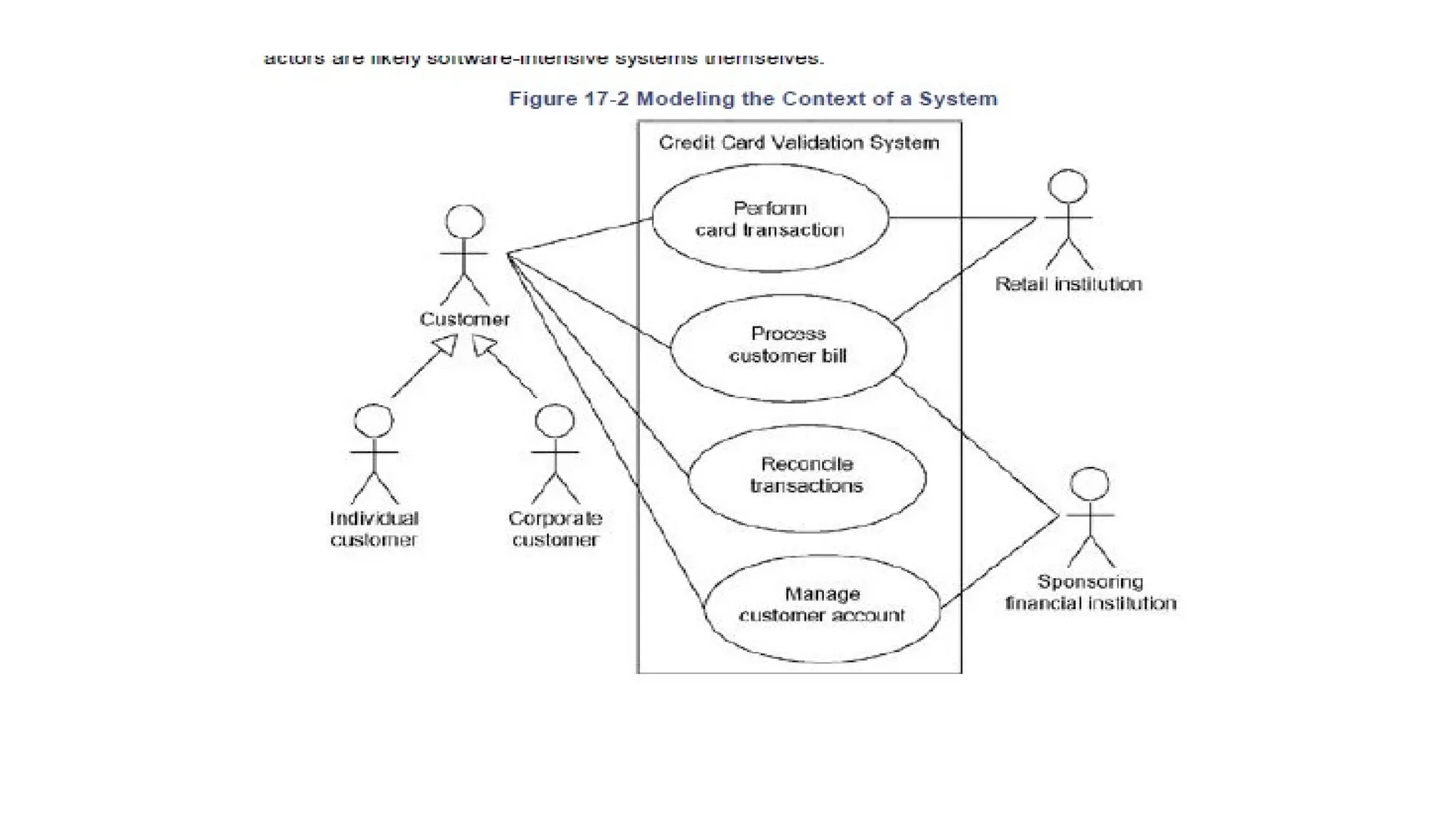
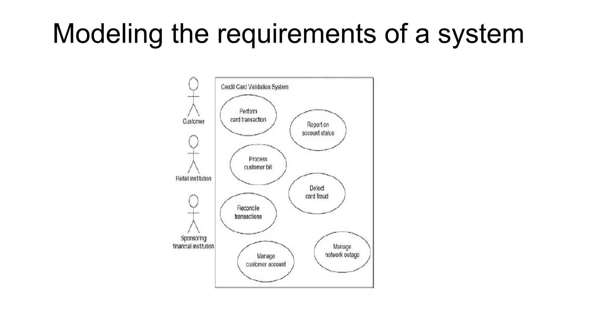
•Modeling the context of a system
• Modeling the requirements of a system
• Forward and reverse engineering
Forward and reverseengineering
• Most of the UML's other diagrams, including class, component, and state chart diagrams, are
clear candidates for forward and reverse engineering because each has an analog in the
executable system. Use case diagrams are a bit different in that they reflect rather than specify
the implementation of a system, subsystem, or class. Use cases describe how an element
behaves, not how that behavior is implemented, so it cannot be directly forward or reverse
engineered.
• A well-structured use case will even specify pre- and postconditions that can be used to define a
test's initial state and its success criteria. For each use case in a use case diagram, you can create
a test case that you can run every time you release a new version of that element, thereby
confirming that it works as required before other elements rely on it.