This document provides definitions and descriptions of various Unified Modeling Language (UML) elements including interface, behavior diagrams, interaction diagrams, structure diagrams, actor, node, component, package, dependency, constraint, note, object lifeline, activation, message, decision, transition, swimlane, class, utility, generalization, binary association, composition, subsystem, object, exception, usage, use case, extends, multi-object, inheritance hierarchy, initial state, final state, object in state, object flow, and state.
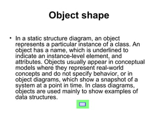


![Object In State shape In an activity diagram, an object in state is an object that is manipulated by a number of successive activities. Each appearance of the object indicates a different phase in its life. To distinguish an object in one phase from that same object in another phase, the state of the object in each phase can be appended in square brackets after the object name (for example, PurchaseOrder[approved]). Object flow arrows connect objects in state to action states, states, and control flow transitions.](https://image.slidesharecdn.com/uml2-2-090906214525-phpapp02/85/Intro-to-UML-2-38-320.jpg)