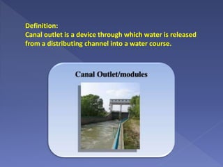
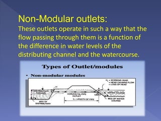
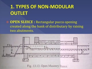
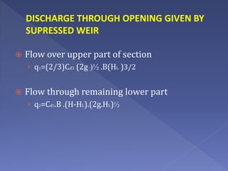
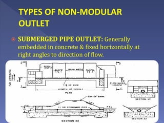
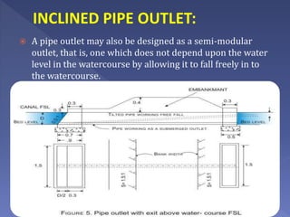
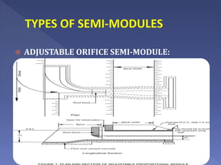
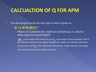
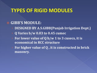
Canal outlets Or
Modules
Definition:
Canal outlet is a device through which water is released
from a distributing channel into a water course.
Requirement:
Structurally strong
With out any moving parts
Difficult for the cultivators to interfere and if so
easily detectable
Work efficiently for small working heads
Can draw fair share of silt and economical.
Classification of Outlets:
Non modular outlets
Semi modular outlets
Modular outlets
Non-Modular outlets:
These outlets operate in such a way that the
flow passing through them is a function of
the difference in water levels of the
distributing channel and the watercourse.
Semi-modular outlets :
The discharge through these outlets depend on
the water level of the distributing channel but is
independent of the water level in the watercourse
so long as the minimum working head required for
their working is available.
Module outlets:
The discharge through modular outlets is
independent of the water levels in the distributing
channel and the watercourse, within reasonable
working limits. This type of outlets may or may
not be equipped with moving parts.
SOME OTHER IMPORTANT
DEFINITIONS
 MINIMUM MODULAR HEAD
 EFFICIENCY OF AN OUTLET
 DROWNING RATIO
 MODULAR LIMIT
 MODULAR RANGE
 OPEN SLUICE : Rectangular pucca opening
created along the bank of distributary by raising
two abutments.
 Flow over upper part of section
› q1=(2/3)Cd1 (2g )½ .B(HL )3/2
 Flow through remaining lower part
› q2=Cd2.B .(H-HL).(2g.HL)½
DISCHARGE THROUGH OPENING GIVEN BY
SUPRESSED WEIR
TYPES OF NON-MODULAR
OUTLET
 SUBMERGED PIPE OUTLET: Generally
embedded in concrete & fixed horizontally at
right angles to direction of flow.
INCLINED PIPE OUTLET:
 A pipe outlet may also be designed as a semi-modular
outlet, that is, one which does not depend upon the water
level in the watercourse by allowing it to fall freely in to
the watercourse.
CALCULATION OF Q FOR PIPE
OUTLETS:
 Discharge through the pipe outlet is given by the formula:
Q = CA (2gH) ½
Q is the discharge; A is the cross sectional area; g is the acceleration due to
gravity; H is difference in water levels of supply channel and watercourse and C is
the coefficient of discharge which depends upon friction factor (f), length (L) and
diameter of the outlet pipe (d) related by the formula:
The coefficient f is the fluid friction factor and its value may be taken as 0.005
and 0.01 for clear and encrusted iron pipes respectively.
2. TYPES OF SEMI-MODULES
 PIPE OUTLET DISCHARGING FREELY
INTO AIR
 VENTURI FLUME OULET OR KENNEDY
GUAGE OUTLET
 OPEN FLUME OUTLET
 ADJUSTABLE ORIFICE SEMI-MODULE
TYPES OF SEMI-MODULES
 PIPE OUTLET DISCHARGING FREELY
INTO AIR: Oldest type of flexible outlet. The
discharge depends only on water level of
distributary.
 Silt Conduction Is quite Good.
 Efficiency is High.
TYPES OF SEMI-MODULES
 VENTURI FLUME OULET: Become obsolete
these days.
 It is an old one & designed by Kennedy in
1906{PUNJAB}
TYPES OF SEMI-MODULES
 OPEN FLUME OUTLET: This is a smooth weir with a
throat constricted sufficiently long to ensure that the controlling
section remains with in the parallel throat for all discharges up to the
maximum.
CALCULATION OF Q FOR OPEN
FLUME OUTLET
 Q = C Bt H3/2
› Where Q is related to the coefficient of discharge, C, as given in the table below;
› Bt is the width of the throat in cm; and H is the height of the full
supply level of the supply channel above the crest level of the outlet in
cm.
TYPES OF SEMI-MODULES
 ADJUSTABLE ORIFICE SEMI-MODULE:
CALCUALTION OF Q FOR APM
 The discharge formula for this type of weir is given as:
› Q = C Bt H1(H2)1/2
 Where Q is related to the coefficient of discharge, C, which is
taken equal to around 0.0403;
 Bt is the width of the throat in cm; H1 is the depth of head available, that is
the difference between the supply channel full supply level and the outlet bed
(crest) level; and H2 is the difference between the supply channel full supply
level and the bottom level of the roof block
3. TYPES OF RIGID MODULES
 GIBB’S MODULE
 KHANNA’S RIGID MODULE
 FOOTE MODULE
TYPES OF RIGID MODULES
 GIBB’S MODULE:
› DESIGNED BY A.S.GIBB{Punjab Irrigation Dept.}
› Q Varies b/w 0.03 to 0.45 cumec
› For lower value of Q b/w 1 to 3 cusecs, it is
economical in RCC structure
› For higher value of Q , it is constructed in brick
masonry.
Canal outlets and modules

Canal outlets and modules

  • 1.
  • 2.
    Definition: Canal outlet isa device through which water is released from a distributing channel into a water course.
  • 3.
    Requirement: Structurally strong With outany moving parts Difficult for the cultivators to interfere and if so easily detectable Work efficiently for small working heads Can draw fair share of silt and economical.
  • 4.
    Classification of Outlets: Nonmodular outlets Semi modular outlets Modular outlets
  • 5.
    Non-Modular outlets: These outletsoperate in such a way that the flow passing through them is a function of the difference in water levels of the distributing channel and the watercourse.
  • 6.
    Semi-modular outlets : Thedischarge through these outlets depend on the water level of the distributing channel but is independent of the water level in the watercourse so long as the minimum working head required for their working is available.
  • 7.
    Module outlets: The dischargethrough modular outlets is independent of the water levels in the distributing channel and the watercourse, within reasonable working limits. This type of outlets may or may not be equipped with moving parts.
  • 8.
    SOME OTHER IMPORTANT DEFINITIONS MINIMUM MODULAR HEAD  EFFICIENCY OF AN OUTLET  DROWNING RATIO  MODULAR LIMIT  MODULAR RANGE
  • 9.
     OPEN SLUICE: Rectangular pucca opening created along the bank of distributary by raising two abutments.
  • 10.
     Flow overupper part of section › q1=(2/3)Cd1 (2g )½ .B(HL )3/2  Flow through remaining lower part › q2=Cd2.B .(H-HL).(2g.HL)½ DISCHARGE THROUGH OPENING GIVEN BY SUPRESSED WEIR
  • 11.
    TYPES OF NON-MODULAR OUTLET SUBMERGED PIPE OUTLET: Generally embedded in concrete & fixed horizontally at right angles to direction of flow.
  • 12.
    INCLINED PIPE OUTLET: A pipe outlet may also be designed as a semi-modular outlet, that is, one which does not depend upon the water level in the watercourse by allowing it to fall freely in to the watercourse.
  • 13.
    CALCULATION OF QFOR PIPE OUTLETS:  Discharge through the pipe outlet is given by the formula: Q = CA (2gH) ½ Q is the discharge; A is the cross sectional area; g is the acceleration due to gravity; H is difference in water levels of supply channel and watercourse and C is the coefficient of discharge which depends upon friction factor (f), length (L) and diameter of the outlet pipe (d) related by the formula: The coefficient f is the fluid friction factor and its value may be taken as 0.005 and 0.01 for clear and encrusted iron pipes respectively.
  • 14.
    2. TYPES OFSEMI-MODULES  PIPE OUTLET DISCHARGING FREELY INTO AIR  VENTURI FLUME OULET OR KENNEDY GUAGE OUTLET  OPEN FLUME OUTLET  ADJUSTABLE ORIFICE SEMI-MODULE
  • 15.
    TYPES OF SEMI-MODULES PIPE OUTLET DISCHARGING FREELY INTO AIR: Oldest type of flexible outlet. The discharge depends only on water level of distributary.  Silt Conduction Is quite Good.  Efficiency is High.
  • 16.
    TYPES OF SEMI-MODULES VENTURI FLUME OULET: Become obsolete these days.  It is an old one & designed by Kennedy in 1906{PUNJAB}
  • 17.
    TYPES OF SEMI-MODULES OPEN FLUME OUTLET: This is a smooth weir with a throat constricted sufficiently long to ensure that the controlling section remains with in the parallel throat for all discharges up to the maximum.
  • 18.
    CALCULATION OF QFOR OPEN FLUME OUTLET  Q = C Bt H3/2 › Where Q is related to the coefficient of discharge, C, as given in the table below; › Bt is the width of the throat in cm; and H is the height of the full supply level of the supply channel above the crest level of the outlet in cm.
  • 19.
    TYPES OF SEMI-MODULES ADJUSTABLE ORIFICE SEMI-MODULE:
  • 20.
    CALCUALTION OF QFOR APM  The discharge formula for this type of weir is given as: › Q = C Bt H1(H2)1/2  Where Q is related to the coefficient of discharge, C, which is taken equal to around 0.0403;  Bt is the width of the throat in cm; H1 is the depth of head available, that is the difference between the supply channel full supply level and the outlet bed (crest) level; and H2 is the difference between the supply channel full supply level and the bottom level of the roof block
  • 21.
    3. TYPES OFRIGID MODULES  GIBB’S MODULE  KHANNA’S RIGID MODULE  FOOTE MODULE
  • 22.
    TYPES OF RIGIDMODULES  GIBB’S MODULE: › DESIGNED BY A.S.GIBB{Punjab Irrigation Dept.} › Q Varies b/w 0.03 to 0.45 cumec › For lower value of Q b/w 1 to 3 cusecs, it is economical in RCC structure › For higher value of Q , it is constructed in brick masonry.