This document provides solutions to problems involving belt drives. It first solves for the tensions and power transmission in a belt drive system connecting two pulleys of different diameters, one running at 200 rpm. Taking into account centrifugal tension, friction, and a maximum tension of 2 kN, it finds the transmitted power is 13.588 kW. It also calculates the efficiencies lost to friction in the system.
![Solution manual - chapter 11 Preapred by Darawan Abdulwahid
1
N1 = 120 r. p. m d1 = 2m t = 5mm = 0.005m d2 = 1m N2 =?
Solution:
1.With no slip
N2
N1
=
d1 + t
d2 + t
→
N2
120
=
2 + 0.005
1 + 0.005
→ N2 = (
2 + 0.005
1 + 0.005
) × 120 = 239.4 r. p. m
2.With a slip of 3%
N2
N1
=
d1 + t
d2 + t
× (1 −
s1 + s2
100
) →
N2
120
=
2 + 0.00
1 + 0.00
× (1 −
3 + 0
100
)
→ N2 = (
2 + 0.005
1 + 0.005
) × (1 −
3 + 0
100
) × 120 = 232.22 r. p. m
v = 600 (m/ min)× (
1min
60s
) = 10m/s μ = 0.3 θ = 160° ×
π
180
= 2.8rad
T = 700N = T1 P =?
Solution:
T1
T2
= eμθ
= e0.3×2.8
= 2.31 → T2 =
T1
2.31
When T1 = 700N → T2 =
700
2.31
= 303N
P = (T1 − T2) × v = (700 − 303) × 10 = 3983W = 3.983KW
1. An engine shaft running at 120 r.p.m. is required to drive a machine shaft by means of a belt. The
pulley on the engine shaft is of 2 m diameter and that of the machine shaft is 1 m diameter. If the
belt thickness is 5 mm ; determine the speed of the machine shaft, when 1. there is no slip ; and
2. there is a slip of 3%. [Ans. 239.4 r.p.m. ; 232.3 r.p.m.]
3. A pulley is driven by a flat belt running at a speed of 600 m/min. The coefficient of friction
between the pulley and the belt is 0.3 and the angle of lap is 160°. If the maximum tension in the
belt is 700 N ; find the power transmitted by a belt. [Ans. 3.983 kW]](https://image.slidesharecdn.com/theoryofmachinessolutionch11-180703103345/85/Theory-of-machines-solution-ch-11-2-320.jpg)
![Solution manual - chapter 11 Preapred by Darawan Abdulwahid
2
b =? P = 7.5kW = 7500W d = 300mm = 0.3m N = 1600r. p. m μ = 0.22
θ = 210° ×
π
180
= 3.665rad T′
= 8N/mm width
Solution:
v =
πdN
60
=
π × 0.3 × 1600
60
= 25.13m/s
T1
T2
= eμθ
= e0.22×3.665
= 2.2396 … … . a
P = (T1 − T2) × v → 7500 = (T1 − T2) × 25.13
→ T1 − T2 =
7500
25.13
= 298.44N → T1 = 298.44 + T2 … … . b
sub a in b ∶
298.44 + T2
T2
= 2.2396 → T2 = 240.761N
T1 = 298.44 + 240.761 = 539.2N
b =
T1
T′
=
539.2
8
= 67.4mm
4. Find the width of the belt, necessary to transmit 7.5 kW to a pulley 300 mm diameter, if the
pulley makes 1600 r.p.m and the coefficient of friction between the belt and the pulley is 0.22.
Assume the angle of contact as 210° and the maximum tension in the belt is not to exceed 8
N/mm width. [Ans. 67.4 mm]](https://image.slidesharecdn.com/theoryofmachinessolutionch11-180703103345/85/Theory-of-machines-solution-ch-11-3-320.jpg)
![Solution manual - chapter 11 Preapred by Darawan Abdulwahid
3
b = 100mm 𝑥 = 2.4m d1 = 450mm = 0.45m μ = 0.3
d2 = 300mm = 0.3m T′
= 14N/m N1 = 120 r. p. m P =?
Solution:
v =
πd1N1
60
=
π × 0.45 × 120
60
= 2.827m/s
α = sin−1
(
d1 − d2
2𝑥
) = sin−1
(
0.45 − 0.3
2 × 2.4
) = 1.79° → 2α = 2 × 1.79° = 3.58°
θ = (180 − 2α) ×
π
180
= (180 − 3.58) ×
π
180
= 3.079 rad
T1
T2
= eμθ
= e0.3×3.079
= 2.518 … … . a
b =
T1
T′
→ 100 =
T1
14
→ T1 = 100 × 14 = 1400N … … . b
sub a in b ∶
T1
T2
= 2.518 → T2 =
T1
2.518
=
1400
2.518
= 555.996N
P = (T1 − T2) × v = (1400 − 555.996) × 2.827
P = 2386W ≈ 2.39kW
5. An open belt 100 mm wide connects two pulleys mounted on parallel shafts with their centers
2.4 m apart. The diameter of the larger pulley is 450 mm and that of the smaller pulley 300 mm.
The coefficient of friction between the belt and the pulley is 0.3 and the maximum stress in the
belt is limited to 14 N/mm width. If the larger pulley rotates at 120 r.p.m., find the maximum
power that can be transmitted. [Ans. 2.39 kW]](https://image.slidesharecdn.com/theoryofmachinessolutionch11-180703103345/85/Theory-of-machines-solution-ch-11-4-320.jpg)
![Solution manual - chapter 11 Preapred by Darawan Abdulwahid
4
b = 125mm = 0.125m t = 6mm = 0.006m d = 750mm 0.75m μ = 0.3
N = 500 θ = 150° ×
π
180
= 2.617rad ρ = 1Mg/m3
= 1000kg/ m3
σ = 2.75Mpa = 2.75 × 10⁶
Pa P =?
Solution:
v =
πdN
60
=
π × 0.75 × 500
60
= 19.634m/s > 10m/s , so we take Tc in the acount
T1
T2
= eμθ
= e0.3×2.617
= 2.1926 … … . a
Tc = mv2
= 𝜌𝑏𝑡𝑙 × v2
= 1000 × 0.125 × 0.006 × 1 × (19.634)2
= 289.12N
T = σbt = 2.75 × 106
× 0.125 × 0.006 = 2062.5N/m2
T = Tc + T1 → T1 = T − Tc = 2062.5 − 289.12 = 1773.38 … … . b
sub a in b ∶
T1
T2
= 2.1926 → T2 =
T1
2.1926
=
1773.38
2.1926
= 808.8N
P = (T1 − T2) × v = (1773.38 − 808.8) × 19.634
P = 18931.1W ≈ 19kW
6. A leather belt 125 mm wide and 6 mm thick, transmits power from a pulley 750 mm diameter
which runs at 500 r.p.m. The angle of lap is 150° and μ = 0.3. If the mass of 1 m3 of leather is 1 Mg
and the stress in the belt is not to exceed 2.75 MPa, find the maximum power that can be
transmitted. [Ans. 19 kW]](https://image.slidesharecdn.com/theoryofmachinessolutionch11-180703103345/85/Theory-of-machines-solution-ch-11-5-320.jpg)
![Solution manual - chapter 11 Preapred by Darawan Abdulwahid
5
P = 35kW = 35000W d = 1.5m N = 300 r. p. m θ =
11
24
× 2π = 2.88 rad
μ = 0.3 t = 9.5mm = 0.095m ρ = 1.1Mg/m3
= 1100 kg/m3
σ = 2.5Mpa = 2.5 × 10⁶
Pa
Solution:
v =
πdN
60
=
π × 1.5 × 300
60
= 23.56m/s
T1
T2
= eμθ
= e0.3×2.88
= 2.37 … … . a
P = (T1 − T2) × v → 35000 = (T1 − T2) × 23.56
→ T1 − T2 =
35000
23.56
= 1485.568N → T1 = 1485.568 + T2 … … . b
sub a in b ∶
1485.568 + T2
T2
= 2.37 → T2 = 1081.39N
→ T1 = 1485.568 + 1081.39 = 2567.96N
Tc = mv2
= 𝜌𝑏𝑡𝑙 × v2
= 1100 × b × 0.095 × 1 × (23.56)2
= 5800.5b
Tc + T1 = σbt → 5800.5b + 2566.96 = 2.5 × 10⁶
× b × 0.095
2566.96 = 237500b − 5800.5b → 2566.96 = 17950b
b =
2566.96
17950
= 0.143 m = 143 mm
P = (T1 − T2) × v = (2566.96 − 17950) × 23.56
P = 35920W ≈ 35.9 kW
7. A flat belt is required to transmit 35 kW from a pulley of 1.5 m effective diameter running at
300 r.p.m. The angle of contact is spread over 11/24 of the circumference and the coefficient of
friction between belt and pulley surface is 0.3. Determine, taking centrifugal tension into
account, width of the belt required. It is given that the belt thickness is 9.5 mm, density of its
material is 1.1 Mg/m3 and the related permissible working stress is 2.5 MPa. [Ans. 143 mm]](https://image.slidesharecdn.com/theoryofmachinessolutionch11-180703103345/85/Theory-of-machines-solution-ch-11-6-320.jpg)
![Solution manual - chapter 11 Preapred by Darawan Abdulwahid
6
N1 = 750r. p. m t = 8mm = 0.008m b = 250mm = 0.25m μ = 0.35
d1 = 350mm = 0.35m d2 = 1350mm = 1.35m 𝑥 = 1350mm = 1.35m
σ = 2.5N/mm2
× 106
= 2.5 × 10⁶
Pa m = 2kg/m P = ?
Solution:
v =
πd1N1
60
=
π × 0.35 × 750
60
= 13.74m/s
Tc = mv2
= 2 × (13.74)2
= 377.82N
sinα = (
d1 − d2
2𝑥
) → α = sin−1
(
0.34 − 1.35
2 × 1.35
) = | − 21.73°| = 21.73° Must be + ive
θ = (180 − 2α) ×
π
180
= (180 − (2 × 21.73)) ×
π
180
= 2.38 rad
T1
T2
= eμθ
= e0.35×2.38
= 2.302 … … . a
T = σbt = Tc + T1 → 2.5 × 106
× 0.25 × 0.008 = 377.82 + T1
5000 − 377.82 = T1 → T1 = 4622.18N … … . b
sub a in b ∶
4622.18
T2
= 2.302 → T2 = 2007.89N
P = (T1 − T2) × v = (4622.18 − 2007.89) × 13.74
P = 35920.34W ≈ 35.9kW
8. A blower is driven by an electric motor though a belt drive. The motor runs at 750 r.p.m. For this
power transmission, a flat belt of 8 mm thickness and 250 mm width is used. The diameter of the
motor pulley is 350 mm and that of the blower pulley 1350 mm. The center distance between these
pulleys is 1350 mm and an open belt configuration is adopted. The pulleys are made out of cast
iron. The frictional coefficient between the belt and pulley is 0.35 and the permissible stress for the
belt material can be taken as 2.5 N/mm² with sufficient factor of safety. The mass of a belt is 2 kg
per meter length. Find the maximum power transmitted without belt slipping in any one of the
pulleys. [Ans. 35.9 kW]](https://image.slidesharecdn.com/theoryofmachinessolutionch11-180703103345/85/Theory-of-machines-solution-ch-11-7-320.jpg)
![Solution manual - chapter 11 Preapred by Darawan Abdulwahid
7
d1 = 1.2m d2 = 0.5m 𝑥 = 3.6m m = 1kg/m T = 2kN = 2000N
N1 = 200r. p. m N2 = 450r. p. m μ = 0.3 1. Tq1 & Tq2 =?
2. P =? 3. Power lost in friction =? Efficiency =?
Solution:
v =
πd1N1
60
=
π × 1.2 × 200
60
= 12.566m/s
α = sin−1
(
d1 − d2
2𝑥
) = sin−1
(
1.2 − 0.5
2 × 3.6
) = 5.579°
θ = (180 − 2α) ×
π
180
= (180 − (2 × 5.579)) ×
π
180
= 2.946 rad
T1
T2
= eμθ
= e0.3×2.946
= 2.42 … … . a
Tc = mv2
= 1 × (12.566)2
= 157.91N
T = Tc + T1 → 2000 = 157.91 + T1 → T1 = 2000 − 157.91 = 1842.09N … … . b
sub a in b ∶
1842.09
T2
= 2.42 → T2 =
1842.09
2.42
= 761.194N
2.
P = (T1 − T2) × v = (1842.09 − 761.194) × 12.556 = 13588W = 13.588kW
9. An open belt drive connects two pulleys 1.2 m and 0.5 m diameter on parallel shafts 3.6 m apart.
The belt has a mass of 1 kg/m length and the maximum tension in it is not to exceed 2 kN. The 1.2
m pulley, which is the driver, runs at 200 r.p.m. Due to the belt slip on one of the pulleys, the
velocity of the driven shaft is only 450 r.p.m. If the coefficient of friction between the belt and the
pulley is 0.3, find : 1. Torque on each of the two shafts, 2. Power transmitted, 3. Power lost in
friction, and 4. Efficiency of the drive.
[Ans. 648.6 N-m, 270.25 N-m ; 13.588 kW ; 0.849 kW ; 93.75%]](https://image.slidesharecdn.com/theoryofmachinessolutionch11-180703103345/85/Theory-of-machines-solution-ch-11-8-320.jpg)
![Solution manual - chapter 11 Preapred by Darawan Abdulwahid
9
𝑥 = 3.5m d1 = 600mm = 0.6m d2 = 300mm = 0.3m P = 6kW = 6000W
N1 = 220r. p. m T′
= 25N/m width t = 5mm = 0.005m μ = 0.35
1. L =? 2. b =? 3. Tₒ =?
Solution:
1. L =
π
2
(d1 + d2) + 2𝑥 +
(d1−d2)2
4𝑥
=
π
2
(0.6 + 0.3) + (2 × 3.5) +
(0.6+0.3)2
4×3.5
= 8.472m
2.
v =
πd1N1
60
=
π × 0.6 × 220
60
= 6.911m/s
α = sin−1
(
0.6 + 0.3
2 × 3.5
) = sin−1
(
0.6 + 0.3
2 × 3.5
) = 7.387°
θ = (180 + 2α) ×
π
180
= (180 + (2 × 7.387)) ×
π
180
= 3.399 rad
T1
T2
= eμθ
= e0.3×3.399
= 3.286 … … . a
P = (T1 − T2) × v → 6000 = (T1 − T2) × 6.911
→ T1 − T2 =
6000
6.911
= 868.181N → T1 = 868.181 + T2 … … . b
sub a in b ∶
868.181 + T2
T2
= 3.286 → T2 = 379.781N
T1 = 868.181 + 379.781 = 1247.926N
b =
T1
T′
=
1247.926
25
= 49.9mm
3.
Tₒ =
T1 + T2
2
=
1247.926 + 379.78
2
= 889.08
10. The power transmitted between two shafts 3.5 metres apart by a cross belt drive round the two
pulleys 600 mm and 300 mm in diameters, is 6 kW. The speed of the larger pulley (driver) is 220
r.p.m. The permissible load on the belt is 25 N/mm width of the belt which is 5 mm thick. The
coefficient of friction between the smaller pulley surface and the belt is 0.35. Determine :
1. necessary length of the belt ; 2. width of the belt, and 3. necessary initial tension in the belt.
[Ans. 8.472 m ; 53 mm ; 888 N]](https://image.slidesharecdn.com/theoryofmachinessolutionch11-180703103345/85/Theory-of-machines-solution-ch-11-10-320.jpg)
![Solution manual - chapter 11 Preapred by Darawan Abdulwahid
10
T = 8mm = 0.008m b = 100mm = 0.1m v = 1600m/min ×
1min
60sec
= 26.67m/s
m = 0.9kg/m θ = 165° ×
π
180
= 2.88rad μ = 0.3 σ = 2MN/m2
= 2 × 10⁶
pa
1. P =? 2. Tₒ =?
Solution:
1.
T1
T2
= eμθ
= e0.3×2.88
= 2.372 … … . a
Tc = mv2
= 0.9 × (26.67)2
= 640N
T = σ × b × t = Tc + T1 → 2 × 106
× 0.1 × 0.008 = 640 + T1
T1 = 1600 − 640 → T1 = 960N … … . b
sub a in b ∶
960
T2
= 2.372 → T2 = 404.72N
P = (T1 − T2) × v → P = (960 − 404.72) × 26.67 = 14809.3W = 14.8kW
2.
Tₒ =
T1 + T2 + 2Tc
2
=
960 + 404.72 + (2 × 640)
2
= 1322.36N
But when we use equation below , we get the same result which given for [Tₒ]∗
Tₒ =
T1 + T2 + Tc
2
=
960 + 404.72 + 640
2
= 1002.36N
-------------------------------------------------------------------------------------------------------------------------------
∗ see a textbook (theory of machines by r. k. bansal)
11. A flat belt, 8 mm thick and 100 mm wide transmits power between two pulleys, running at
1600 m/min. The mass of the belt is 0.9 kg/m length. The angle of lap in the smaller pulley is 165°
and the coefficient of friction between the belt and pulley is 0.3. If the maximum permissible stress
in the belt is 2 MN/m2, find : 1. maximum power transmitted ; and 2. initial tension in the belt
[Ans. 14.83 kW ; 1002 N]](https://image.slidesharecdn.com/theoryofmachinessolutionch11-180703103345/85/Theory-of-machines-solution-ch-11-11-320.jpg)
![Solution manual - chapter 11 Preapred by Darawan Abdulwahid
11
d = 400mm = 0.4m N = 200r. p. m θ = 160° ×
π
180
= 2.79rad μ = 0.25
P = 3kW = 3000W
Solution:
v =
πdN
60
=
π × 0.4 × 200
60
= 4.188m/s
T1
T2
= eμθ
= e0.25×2.79
= 2 … … . a
P = (T1 − T2) × v → 3000 = (T1 − T2) × 4.188
→ T1 − T2 =
3000
4.188
= 716.33N → T1 = 716.33 + T2 … … . b
sub a in b ∶
716.33 + T2
T2
= 2 → T2 = 716.33N
T1 = 716.33 + 716.33 = 1432.66N
Tₒ =
T1 + T2
2
=
1432.66 + 716.33
2
= 1079.495N … … . e
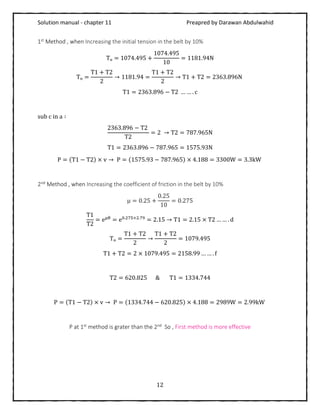
12. An open belt connects two flat pulleys. The smaller pulley is 400 mm diameter and runs at 200
r.p.m. The angle of lap on this pulley is 160° and the coefficient of friction between the belt and
pulley face is 0.25. The belt is on the point of slipping when 3 kW is being transmitted. Which of the
following two alternatives would be more effective in order to increase the power :
1. Increasing the initial tension in the belt by 10 per cent, and
2. Increasing the coefficient of friction by 10 per cent by the application of a suitable dressing to the
belt? [Ans. First method is more effective]](https://image.slidesharecdn.com/theoryofmachinessolutionch11-180703103345/85/Theory-of-machines-solution-ch-11-12-320.jpg)
![Solution manual - chapter 11 Preapred by Darawan Abdulwahid
13
m = 0.9kg/m T = 2.2kN = 2200N θ = 170° ×
π
180
= 2.967rad μ = 0.17
2β = 45° 1. v =? 2. P =?
Solution:
For maximum power we can write :
1.
v = √
T
3m
= √
2200
3 × 0.9
= 28.54m/s
T1
T2
= e
μθ×
1
sinβ = 𝑒0.17×2.967×
1
sin22.5 = 3.73 … … . a
Tc = mv2
= 0.9 × (28.54)2
= 733N
T1 = T − Tc = 2200 − 733 = 1466.67N … … . b
sub a in b ∶
1466.67
T2
= 3.73 → T2 =
1466.67
3.73
= 393.2N
2.
P = (T1 − T2) × v → P = (1466.67 − 393.2) × 28.54 = 30636.833W = 3.7kW
14. Power is transmitted between two shafts by a V-belt whose mass is 0.9 kg/m
length. The maximum permissible tension in the belt is limited to 2.2 kN. The angle of
lap is 170° and the groove angle 45°. If the coefficient of friction between the belt
and pulleys is 0.17, find : 1. velocity of the belt for maximum power ; and 2. power
transmitted at this velocity. [Ans. 28.54 m/s ; 30.7 kW]](https://image.slidesharecdn.com/theoryofmachinessolutionch11-180703103345/85/Theory-of-machines-solution-ch-11-14-320.jpg)
![Solution manual - chapter 11 Preapred by Darawan Abdulwahid
14
𝑥 = 1m P = 100kW d1 = 300mm = 0.3m N1 = 1000 r. p. m
N2 = 375 r. p. m 2β = 40° A = 400mm2
= 4 × 10⁻⁴
m2
σ = 2.1Mpa = 2.1 × 10⁶
Pa ρ = 1100kg/m3
μ = 0.28 n =?
Solution:
N2
N1
=
d1
d2
→ d2 =
N1 × d1
N2
=
1000 × 0.3
375
= 0.8m
α = sin−1
(
d1 − d2
2𝑥
) = sin−1
(
0.3 − 0.8
2 × 1
) = | − 14.477°| = 14.477°
θ = (180 − 2α) ×
π
180
= (180 − (2 × 14.477°)) ×
π
180
= 2.636 rad
T1
T2
= e
μθ×
1
sinβ = 𝑒0.28×2.636×
1
sin20 = 8.655 … … . a
T = σ × A = 2.1 × 106
× 4 × 10−4
= 840N
v =
πd1N1
60
=
π × 0.3 × 1000
60
= 15.7m/s
Tc = ρAv2
= 1100 × 4 × 10−4
× (15.7)2
= 108.565N
T1 = T − Tc = 840 − 108.565 = 731.43N … … . b
sub a in b ∶
T1
T2
= 8.655 → T2 =
731.43
8.655
= 85.393N
P = (T1 − T2) × v → P = (731.43 − 85.393) × 15.7 = 10142.7 = 10.14kW
n =
Total power
Power per belt
=
100
10.14
= 9.86 = 10 belts
15. Two shafts whose centers are 1 m apart are connected by a V-belt drive. The driving pulley is
supplied with 100 kW and has an effective diameter of 300 mm. It runs at 1000 r.p.m. while the
driven pulley runs at 375 r.p.m. The angle of groove on the pulleys is 40°. The permissible tension in
400 mm² cross-sectional area belt is 2.1 MPa. The density of the belt is 1100 kg/m³. The coefficient
of friction between the belt and pulley is 0.28. Estimate the number of belts required. [Ans. 10]](https://image.slidesharecdn.com/theoryofmachinessolutionch11-180703103345/85/Theory-of-machines-solution-ch-11-15-320.jpg)
![Solution manual - chapter 11 Preapred by Darawan Abdulwahid
15
P = 230kW = 230 × 103
W d = 1m N = 450 r. p. m T = 800N
m = 0.46
kg
meter
θ = 160° ×
π
180
= 2.79rad 2β = 45° μ = 0.3 n =?
Solution:
v =
πdN
60
=
π × 1 × 450
60
= 23.56m/s
T1
T2
= e
μθ×
1
sinβ = 𝑒0.3×2.79×
1
sin22.5 = 8.9 … … . a
Tc = mv2
= 0.46 × (23.56)2
= 255.33N
T1 = T − Tc = 800 − 255.33 = 544.67N … … . b
sub a in b ∶
T1
T2
= 8.9 → T2 =
544.67
8.9
= 61.2N
P = (T1 − T2) × v → P = (544.67 − 61.2) × 23.56 = 11390.5W = 11.39kW
n =
Total power
Power per belt
=
230
11.39
= 20.2 = 21 belts
16. A rope drive is required to transmit 230 kW from a pulley of 1 metre diameter running at 450
r.p.m. The safe pull in each rope is 800 N and the mass of the rope is 0.46 kg per metre length. The
angle of lap and the groove angle is 160° and 45° respectively. If the coefficient of friction between
the rope and the pulley is 0.3, find the number of ropes required. [Ans. 21]](https://image.slidesharecdn.com/theoryofmachinessolutionch11-180703103345/85/Theory-of-machines-solution-ch-11-16-320.jpg)
![Solution manual - chapter 11 Preapred by Darawan Abdulwahid
16
𝑥 = 3m d1 = 3m d2 = 2m 2β = 40° m = 3.7kg per meter μ = 0.15
T = 20kN = 20000N P =? N2 =?
Solution:
α = sin−1
(
d1 − d2
2𝑥
) = sin−1
(
3 − 2
2 × 3
) = 14.477°
θ = (180 − 2α) ×
π
180
= (180 − (2 × 14.477°)) ×
π
180
= 2.636 rad
T1
T2
= e
μθ×
1
sinβ = 𝑒0.15×2.636×
1
sin20 = 3.177 … … . a
For maximum power we can write :
Tc =
T
3
=
20000
3
= 6666.67N
v = √
T
3m
= √
20000
3 × 3.7
= 42.447m/s
T1 = T − Tc = 20000 − 6666.67 = 13333.33N … … . b
sub a in b ∶
T1
T2
= 3.177 → T2 =
13333.33
3.177
= 4196.8N
P = (T1 − T2) × v → P = (13333.33 − 4196.8) × 42.447 = 387818.28W = 387.822kW
v =
πd2N2
60
→ N2 =
v × 60
π × d2
=
42.447 × 60
π × 2
= 405.3 r. p. m
17. Power is transmitted between two shafts, 3 metres apart by an open wire rope passing round
two pulleys of 3 metres and 2 metres diameters respectively, the groove angle being 40°. If the
rope has a mass of 3.7 kg per metre length and the maximum working tension in rope is 20 kN,
determine the maximum power that the rope can transmit and the corresponding speed of the
smaller pulley. The coefficient of friction being 0.15. [Ans. 400 kW ; 403.5 r.p.m.]](https://image.slidesharecdn.com/theoryofmachinessolutionch11-180703103345/85/Theory-of-machines-solution-ch-11-17-320.jpg)
![Solution manual - chapter 11 Preapred by Darawan Abdulwahid
17
P = 75kW = 75000W d1 = 1.5m 2β = 45° N1 = 200 r. p. m μ = 0.3
θ = 160° ×
π
180
= 2.79rad m = 0.6kg per meter T = 800N n =? Tₒ =?
Solution:
v =
πd1N1
60
=
π × 1.5 × 200
60
= 15.7m/s
T1
T2
= e
μθ×
1
sinβ = 𝑒0.3×2.79×
1
sin22.5 = 8.91 … … . a
Tc = mv2
= 0.6 × (15.7)2
= 148.04N
T1 = T − Tc = 800 − 148.04 = 651.955N … … . b
sub a in b ∶
T1
T2
= 8.91 → T2 =
651.955
8.91
= 73.056N
P = (T1 − T2) × v → P = (651.955 − 73.056) × 15.7 = 9088.714W = 9.09kW
n =
Total power
Power per belt
=
75
9.09
= 8.25 = 9 belts
-------------------------------------------------------------------------------------------------------------------------------
Summer 2016 _Edited 2017
Contact me
Gmail : Darawan .me @gmail.com
18. A rope drive transmits 75 kW through a 1.5 m diameter, 45° grooved pulley rotating at 200
r.p.m. The coefficient of friction between the ropes and the pulley grooves is 0.3 and the angle of
lap is 160°. Each rope has a mass of 0.6 kg/m and can safely take a pull of 800 N. Taking centrifugal
tension into account determine : 1. the number of ropes required for the drive, and 2. initial rope
tension. [Ans. 9 ; 510.2 N]](https://image.slidesharecdn.com/theoryofmachinessolutionch11-180703103345/85/Theory-of-machines-solution-ch-11-18-320.jpg)