
Recommended
Recommended
More Related Content
What's hot
What's hot (20)
Similar to Solucionario faires
Similar to Solucionario faires (20)
Recently uploaded
Recently uploaded (20)
Solucionario faires
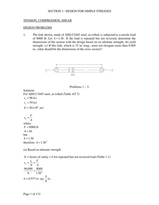
- 1. SECTION 1– DESIGN FOR SIMPLE STRESSES TENSION, COMPRESSION, SHEAR DESIGN PROBLEMS 1. The link shown, made of AISI C1045 steel, as rolled, is subjected to a tensile load of 8000 lb. Let h =1.5b . If the load is repeated but not reversed, determine the dimensions of the section with the design based on (a) ultimate strength, (b) yield strength. (c) If this link, which is 15 in. long., must not elongate more than 0.005 in., what should be the dimensions of the cross section? F sd = where F = 8000 lb A = bh but h =1.5b therefore 2 A =1.5b F s s u d = = 8000 96,000 Page 1 of 131 Problems 1 – 3. Solution: For AISI C1045 steel, as rolled (Table AT 7) s ksi u = 96 s ksi y = 59 E psi 6 = 30×10 A (a) Based on ultimate strength N = factor of safety = 6 for repeated but not reversed load (Table 1.1) A N 2 1.5 6 b = 5 b = 0.577 in say in 8 .
- 2. SECTION 1– DESIGN FOR SIMPLE STRESSES 15 =1.5 = h b in 16 (b) Based on yield strength N = factor of safety = 3 for repeated but not reversed load (Table 1.1) F A s s u d = = N 8000 2 1.5 59,000 3 b = 9 b = 0.521in say in 27 FL 1 Page 2 of 131 16 . h b in 32 =1.5 = (c) Elongation = FL AE d = where, d = 0.005 in F = 8000 lb E psi 6 = 30×10 L =15 in 2 A =1.5b then, AE d = ( 8000 )( 15 ) ( 1.5 2 )( 30 10 6 ) 0.005 × = b 3 b = 0.730 in say in 4 . h b in 8 =1.5 =1 2. The same as 1 except that the material is malleable iron, ASTM A47-52, grade 35 018. Solution: For malleable iron, ASTM A47-52, grade 35 018(Table AT 6) s ksi u = 55 s ksi y = 36.5 E psi 6 = 25×10
- 3. SECTION 1– DESIGN FOR SIMPLE STRESSES F s= d A where F = 8000 lb A = bh but h =1.5b therefore A =1.5b 2 (a) Based on ultimate strength N = factor of safety = 6 for repeated but not reversed load (Table 1.1) F A s s u d = = N 8000 2 1.5 55,000 6 b = 7 b = 0.763 in say in 5 F s s u d = = 8000 36,500 1 Page 3 of 131 8 . h b in 16 =1.5 =1 (b) Based on yield strength N = factor of safety = 3 for repeated but not reversed load (Table 1.1) A N 2 1.5 3 b = 11 b = 0.622 in say in 16 . h b in 32 =1.5 =1 (c) Elongation = FL AE d = where, d = 0.005 in F = 8000 lb E psi 6 = 25×10 L =15 in 2 A =1.5b then,
- 4. SECTION 1– DESIGN FOR SIMPLE STRESSES FL AE d = ( 8000 )( 15 ) ( 1.5 2 )( 25 10 6 ) 0.005 5 F sd = where F = 8000 lb A = bh but h =1.5b therefore 2 A =1.5b F s s u d = = 8000 30,000 25 Page 4 of 131 × = b 7 b = 0.8 in say in 8 . h b in 16 =1.5 =1 3. The same as 1 except that the material is gray iron, ASTM 30. Solution: For ASTM 30 (Table AT 6) s ksi u = 30 , no y s E psi 6 =14.5×10 Note: since there is no y s for brittle materials. Solve only for (a) and (c) A (a) Based on ultimate strength N = factor of safety = 7 ~ 8 say 7.5 (Table 1.1) A N 2 1.5 7.5 b = 3 1 . b =1.1547 in say in 16 h b in 32 =1.5 =1 (c) Elongation = FL AE d = where, d = 0.005 in F = 8000 lb E psi 6 =14.5×10
- 5. SECTION 1– DESIGN FOR SIMPLE STRESSES L =15 in 2 A =1.5b then, FL AE d = ( 8000 )( 15 ) ( 1.5 2 )( 14.5 10 6 ) 0.005 19 p 2 = = = = N F u s N F y s Page 5 of 131 × = b 1 1 . b =1.050 in say in 16 h b in 32 =1.5 =1 4. A piston rod, made of AISI 3140 steel, OQT 1000 F (Fig. AF 2), is subjected to a repeated, reversed load. The rod is for a 20-in. air compressor, where the maximum pressure is 125 psig. Compute the diameter of the rod using a design factor based on (a) ultimate strength, (b) yield strength. Solution: From Fig. AF 2 for AISI 3140, OQT 1000 F s ksi u =152.5 s ksi y =132.5 F force (20) (125) 39,270 lb 39.27 kips 4 From Table 1.1, page 20 = 8 u N = 4 y N (a) Based on ultimate strength u A = ( 8 )( 39.27 ) 152.5 4 2 d = p 5 1 d =1.62 in say in 8 (b) Based on yield strength y A = ( 4 )( 39.27 ) 132.5 4 2 d = p
- 6. SECTION 1– DESIGN FOR SIMPLE STRESSES 1 1 d =1.23 in say in p p p = − = − = 3 D 2 N F = i = u = 7 8 2 2 = p p p = − = − = 3 D 2 N F = i = y = Page 6 of 131 4 5. A hollow, short compression member, of normalized cast steel (ASTM A27-58, 65 ksi), is to support a load of 1500 kips with a factor of safety of 8 based on the ultimate strength. Determine the outside and inside diameters if o i D = 2D . Solution: s ksi u = 65 = 8 u N F =1500 kips ( ) ( ) D 4 3 4 4 4 2 2 2 2 2 i o i i i A D D D D ( 8 )( 1500 ) 65 4 s u A p 7 8 D in i = 8.85 say in 8 3 17 D D in o i 8 4 = = 6. A short compression member with o i D = 2D is to support a dead load of 25 tons. The material is to be 4130 steel, WQT 1100 F. Calculate the outside and inside diameters on the basis of (a) yield strength, (b) ultimate strength. Solution: From Table AT 7 for 4130, WQT 1100 F s ksi u =127 s ksi y =114 From Table 1.1 page 20, for dead load = 3 ~ 4 u N , say 4 =1.5 ~ 2 y N , say 2 Area, ( ) ( ) D 4 3 4 4 4 2 2 2 2 2 i o i i i A D D D D F = 25 tons = 50 kips (a) Based on yield strength ( 2 )( 50 ) 114 4 y s A p
- 7. SECTION 1– DESIGN FOR SIMPLE STRESSES 5 D in i = 0.61 say in 2 2 = 3 D 2 N F = i = u = 2 2 = FL d = or p 4 × N F 3 7000 s = y = = 47,534 y Page 7 of 131 8 1 1 5 D D in o i 8 4 = = (b) Based on ultimate strength ( 4 )( 50 ) 127 4 s u A p 7 D in i = 0.82 say in 8 3 1 7 D D in o i 8 4 = = 7. A round, steel tension member, 55 in. long, is subjected to a maximum load of 7000 lb. (a) What should be its diameter if the total elongation is not to exceed 0.030 in? (b) Choose a steel that would be suitable on the basis of yield strength if the load is gradually applied and repeated (not reversed). Solution: (a) AE FL E A d = where, F = 7000 lb L = 55 in d = 0.030 in E psi 6 = 25×10 ( )( ) ( )( 6 ) 2 7000 55 0.030 30 10 A = d = 3 d = 0.74 in say in 4 (b) For gradually applied and repeated (not reversed) load = 3 y N ( )( ) ( ) psi A 0.75 4 2 p s ksi y » 48 say C1015 normalized condition ( s ksi y = 48 ) 8. A centrifuge has a small bucket, weighing 0.332 lb. with contents, suspended on a manganese bronze pin (B138-A, ½ hard) at the end of a horizontal arm. If the pin is in double shear under the action of the centrifugal force, determine the diameter
- 8. SECTION 1– DESIGN FOR SIMPLE STRESSES needed for 10,000 rpm of the arm. The center of gravity of the bucket is 12 in. from the axis of rotation. Solution: From Table AT 3, for B138-A, ½ hard s ksi us = 48 r W F 2 = w g where W = 0.332 lb 2 g = 32.2 fps p p 2 10,000 2 W 0.332 = w 2 = 2 = = F 1047 1 11,300 11.3 N F u s 4 11.3 2 2 = 1 =1 . (a) What force will cause breakage? (b) For a design factor of 4 based Page 8 of 131 ( ) 1047 sec 60 60 rad n = = = w r =12 in r ( ) ( ) lb kips g 32.2 From Table 1.1, page 20 N = 3 ~ 4 , say 4 u A = ( )( ) 48 4 d p for double shear 25 d = 0.774 in say in 32 CHECK PROBLEMS 3 = and 9. The link shown is made of AISIC1020 annealed steel, with b in 4 h in 2 on the ultimate strength, what is the maximum allowable load? (c) If N = 2.5 based on the yield strength, what is the allowable load? Problem 9.
- 9. SECTION 1– DESIGN FOR SIMPLE STRESSES Solution: For AISI C1020 annealed steel, from Table AT 7 s ksi u = 57 s ksi y = 42 (a) F s A u = 3 in bh A = s A 3 in bh A = 57 1.125 = = s A 3 in bh A = 42 1.125 = = sL sL 57.6 5 d = = = Page 9 of 131 2 1.125 1 1 2 4 = = F = (57)(1.125) = 64 kips (b) u u N F = = 4 u N 2 1.125 1 1 2 4 = = ( )( ) F 16 kips 4 (c) y y N F = = 2.5 y N 2 1.125 1 1 2 4 = = ( )( ) F 18.9 kips 2 10. A ¾-in.bolt, made of cold-finished B1113, has an effective stress area of 0.334 sq. in. and an effective grip length of 5 in. The bolt is to be loaded by tightening until the tensile stress is 80 % of the yield strength, as determined by measuring the total elongation. What should be the total elongation? Solution: E d = from Table AT 7 for cold-finished B1113 s ksi y = 72 then, s s ( ) ksi y = 0.80 = 0.8 72 = 57.6 E 30 10 psi 30,000 ksi 6 = × = ( )( ) in E 0.0096 30,000
- 10. SECTION 1– DESIGN FOR SIMPLE STRESSES 11. A 4-lb. weight is attached by a 3/8-in. bolt to a rotating arm 14-in. from the center of rotation. The axis of the bolts is normal to the plane in which the centrifugal force acts and the bolt is in double shear. At what speed will the bolt shear in two if it is made of AISI B1113, cold finish? Solution: From Table AT 7, s ksi psi us = 62 = 62,000 3 ( ) 2 1 2 in A = W F us = = 2 w 4 2 w = p n 2 = = F = = = n holes Page 10 of 131 2 0.2209 8 4 = p r s A g (14) (62,000)(0.2209) 32.2 w = 88.74 rad sec 88.74 60 w n = 847 rpm 12. How many ¾-in. holes could be punched in one stroke in annealed steel plate of AISI C1040, 3/16-in. thick, by a force of 60 tons? Solution: For AISI C1040, from Figure AF 1 s ksi u = 80 s s ( ) ksi ksi us u = 0.75 = 0.75 80 = 60 A =p dt F = 60 tons =120 kips n = number of holes 120 ( )( ) 9 0.2209 60 us As 13. What is the length of a bearing for a 4-in. shaft if the load on the bearing is 6400 lb. and the allowable bearing pressure is 200 psi of the projected area? Solution: pDL =W where p = 200 psi D = 4 in W = 6400 lb
- 11. SECTION 1– DESIGN FOR SIMPLE STRESSES (200)(4)L = 6400 L = 8 in BENDING STRESSES DESIGN PROBLEMS 14. A lever keyed to a shaft is L =15 in long and has a rectangular cross section of h = 3t . A 2000-lb load is gradually applied and reversed at the end as shown; the material is AISI C1020, as rolled. Design for both ultimate and yield strengths. (a) What should be the dimensions of a section at a =13 in ? (b) at b = 4 in ? (c) What should be the size where the load is applied? 3 th I = , moment of inertial 4 h Page 11 of 131 Problem 14. Solution: For AISI C1020, as rolled, Table AT 7 s ksi u = 65 s ksi y = 49 Design factors for gradually applied and reversed load = 8 u N = 4 y N 12 but h = 3t 36 I = Moment Diagram (Load Upward)
- 12. SECTION 1– DESIGN FOR SIMPLE STRESSES Based on ultimate strength s u N u s = (a) Fac Mc s = = h 65 3.86 = = = 1 1 Fbc Mc s = = h 65 2.61 = = = Page 12 of 131 I I 2 c = F = 2000 lbs = 2 kips ( )( ) = = 36 2 2 13 8 4 h h s h = 3.86 in in h t 1.29 3 3 say h in in 2 = 4.5 = 4 t in in 2 =1.5 =1 (b) I I 2 c = F = 2000 lbs = 2 kips ( )( ) = = 36 2 2 4 8 4 h h s h = 2.61in in h t 0.87 3 3 say h = 3 in t =1in (c)
- 13. SECTION 1– DESIGN FOR SIMPLE STRESSES − 4.5 3 − 13 4 − h 4 3 = h = 2.33 in − 1.5 1 − 13 4 − t 4 1 = t = 0.78 in say 5 h = 2.625 in or h in Page 13 of 131 8 = 2 15. A simple beam 54 in. long with a load of 4 kips at the center is made of cast steel, SAE 080. The cross section is rectangular (let h » 3b ). (a) Determine the dimensions for N = 3 based on the yield strength. (b) Compute the maximum deflection for these dimensions. (c) What size may be used if the maximum deflection is not to exceed 0.03 in.? Solution: For cast steel, SAE 080 (Table AT 6) s ksi y = 40 E psi 6 = 30×10
- 14. SECTION 1– DESIGN FOR SIMPLE STRESSES From Table AT 2 Max. 3 bh 4 h Mc s y = = h 40 4.18 = = = 1 1 4.5 = 4 , in in 3 3 FL
- 15. 48 3 FL 4000 54 36 4.79 = = = 3 5.25 = 5.25 = 5 , in in Page 14 of 131 ( )( ) kips in FL 4 54 M = = = 54 − 4 4 12 I = but h = 3b 36 I = (a) I N s y 2 c = ( ) = 36 2 54 3 4 h h h = 4.18 in in h b 1.39 3 3 say h in 2 h b 2 = = = = 1.5 1 3 3 (b) ( )( ) ( ) ( )( ) in EI 0.0384 4000 54 1.5 4.5 12 48 30 10 6 = × d = = (c) = 36 48 4 3 h E d ( )( ) 3 ( ) 48 ( 30 10 6 )( 4 ) 0.03 × h = h = 4.79 in in h b 1.60 3 3 1 say h in in 4 h b 4 = = = = 1.75 1 3 3
- 16. SECTION 1– DESIGN FOR SIMPLE STRESSES 16. The same as 15, except that the beam is to have a circular cross section. Solution: (a) Mc I s = y = N s y 4 d p = 64 I d 2 c = 32 d 2 M = 4 3 64 32 54 40 1 3 FL 48 4 d FL 64 3 64 E d 64 4000 54 1 Page 15 of 131 d d M s p p = ( ) 3 3 p d = d = 3.46 in say d in 2 = 3 (b) EI d = 64 I p = ( ) ( )( ) ( )( )( ) in E d 0.0594 64 4000 54 3 48 30 10 3.5 48 6 4 4 3 = × = = p p d (c) 48 ( 4 ) FL p d = ( )( ) 3 ( 6 )( ) 4 48 30 10 0.03 × p d = d = 4.15 in say d in 4 = 4 17. A simple beam, 48 in. long, with a static load of 6000 lb. at the center, is made of C1020 structural steel. (a) Basing your calculations on the ultimate strength, determine the dimensions of the rectangular cross section for h = 2b . (b) Determine the dimensions based on yield strength. (c) Determine the dimensions using the principle of “limit design.”
- 17. SECTION 1– DESIGN FOR SIMPLE STRESSES Solution: From Table AT 7 and Table 1.1 s ksi u = 65 s ksi y = 48 = 3 ~ 4 u N , say 4 =1.5 ~ 2 y N , say 2 ( 6 )( 48 ) Mc h 3 bh h 4 h 12 2 s = u = 65 Page 16 of 131 in kips FL M = = = 72 − 4 4 I s = 2 c = 12 I = but 2 b = 24 I = M 4 3 24 h h h M s = = (a) Based on ultimate strength 3 12 h M N s u ( ) 3 12 72 4 h = h = 3.76 in
- 18. SECTION 1– DESIGN FOR SIMPLE STRESSES 3.76 = = = 7 3.75 = 3.75 = 3 , in in s y = = 48 3.30 = = = 3 3.5 = 3.5 = 3 , in in 2 bh 2 2.29 = = = 1 2.5 = 2.5 = 2 , in in Page 17 of 131 in h b 1.88 2 2 3 say h in in 4 h b 8 = = = = 1.875 1 2 2 (b) Based on yield strength 3 12 h M N s y ( ) 3 12 72 2 h = h = 3.30 in in h b 1.65 2 2 1 say h in in 2 h b 4 = = = = 1.75 1 2 2 (c) Limit design (Eq. 1.6) 4 M sy = ( ) 4 72 48 2 h h = h = 2.29 in in h b 1.145 2 2 1 say h in in 2 h b 4 = = = = 1.25 1 2 2 18. The bar shown is subjected to two vertical loads, 1 F and 2 F , of 3000 lb. each, that are L =10 in apart and 3 in. ( a , d ) from the ends of the bar. The design factor is 4 based on the ultimate strength; h = 3b . Determine the dimensions h and b if the bar is made of (a) gray cast iron, SAE 111; (b) malleable cast iron, ASTM A47- 52, grade 35 018; (c) AISI C1040, as rolled (Fig. AF 1). Sketch the shear and moment diagrams approximately to scale.
- 19. SECTION 1– DESIGN FOR SIMPLE STRESSES 3 bh h 3 h h 3 h 4 I = Mc s s u = 30 2.78 = = = Page 18 of 131 Problems18, 19. Solution: F F R R 3000 lb 1 2 1 2 = = = = Moment Diagram M = R a = (3000)(3) = 9000 lbs − in = 9 kips − in 1 N = factor of safety = 4 based on u s 12 I = 2 c = 12 36 = (a) For gray cast iron, SAE 111 s ksi u = 30 , Table AT 6 18 2 M 4 3 36 h h h M I N = = = ( ) 3 18 9 4 h s = = h = 2.78 in in h b 0.93 3 3 say h = 3.5 in , b =1in (b) For malleable cast iron, ASTM A47-52, grade 35 018
- 20. SECTION 1– DESIGN FOR SIMPLE STRESSES s ksi u = 55 , Table AT 6 Mc s s u = 55 2.28 = = = 1 3 = = 2 , b in Mc s s u = 90 1.93 = = = 7 5 = =1 , b in Page 19 of 131 18 2 M 4 3 36 h h h M I N = = = ( ) 3 18 9 4 h s = = h = 2.28 in in h b 0.76 3 3 say h in 4 4 (c) For AISI C1040, as rolled s ksi u = 90 , Fig. AF 1 18 2 M 4 3 36 h h h M I N = = = ( ) 3 18 9 4 h s = = h =1.93 in in h b 0.64 3 3 say h in 8 8 19. The same as 18, except that 1 F acts up ( 2 F acts down). Solution: [ = 0] A M R R 1875 lb 1 2 = =
- 21. SECTION 1– DESIGN FOR SIMPLE STRESSES Shear Diagram Moment Diagram M =maximum moment = 5625 lb-in = 5.625 kips-in (a) For gray cast iron M 3 18 h s s = u = N ( ) 18 5.625 3 30 4 h = h = 2.38 in 2.38 = = = 1 3 = = 2 , b in s s = u = 18 5.625 55 1.95 = = = 7 5 = =1 , b in Page 20 of 131 in h b 0.79 3 3 say h in 4 4 (b) For malleable cast iron 3 18 h M N ( ) 3 4 h = h =1.95 in in h b 0.65 3 3 say h in 8 8
- 22. SECTION 1– DESIGN FOR SIMPLE STRESSES (c) For AISI C1040, as rolled M 3 18 h s s = u = N ( ) 18 5.625 3 90 4 h = h =1.65 in 1.65 = = = 1 1 = =1 , b in Page 21 of 131 in h b 0.55 3 3 say h in 2 2 20. The bar shown, supported at A and B , is subjected to a static load F of 2500 lb. at q = 0 . Let d = 3 in , L =10 in and h = 3b . Determine the dimensions of the section if the bar is made of (a) gray iron, SAE 110; (b) malleable cast iron, ASTM A47-52, grade 32 510; (c) AISI C1035 steel, as rolled. (d) For economic reasons, the pins at A, B, and C are to be the same size. What should be their diameter if the material is AISI C1035, as rolled, and the mounting is such that each is in double shear? Use the basic dimensions from (c) as needed. (e) What sectional dimensions would be used for the C1035 steel if the principle of “limit design” governs in (c)? Problems 20, 21. Solution:
- 23. SECTION 1– DESIGN FOR SIMPLE STRESSES [ = 0] A M 3 =13(2500) B R 3 bh 4 h h 2 Mc s = s s = u = 20 Page 22 of 131 R lb B =10,833 [ = 0] B M 3 =10(2500) A R R lb A = 8333 Shear Diagram Moment Diagram M = (2500)(10) = 25,000 lb − in = 25 kips − in h = 3b 12 I = 36 I = 2 c = 18 M 4 3 36 h h h M I = = (a) For gray cast iron, SAE 110 s ksi u = 20 , Table AT 6 N = 5 ~ 6 , say 6 for cast iron, dead load 3 18 h M N ( ) 3 18 25 6 h =
- 24. SECTION 1– DESIGN FOR SIMPLE STRESSES h = 5.13 in in h = = b 1.71 3 1 3 = 5 , b in say h in 4 s s = u = 52 = = 3 1 = 3 , b in s s = u = 85 = = R s s su B s = = p p = A 2 D D 10.833 64 = = Page 23 of 131 4 =1 (b) For malleable cast iron, ASTM A47-32 grade 32510 s ksi u = 52 , s ksi y = 34 N = 3 ~ 4 , say 4 for ductile, dead load 3 18 h M N ( ) 3 18 25 4 h = h = 3.26 in in h b 1.09 3 say h in 4 4 =1 (c) For AISI C1035, as rolled s ksi u = 85 , s ksi y = 55 N = 4 , based on ultimate strength 3 18 h M N ( ) 3 18 25 4 h = h = 2.77 in in h b 0.92 3 say h = 3 in , b =1in (d) For AISI C1035, as rolled s ksi su = 64 N = 4 , R kips B =10.833 A N 2 2 4 2 = 2 2 4 D ss p D = 0.657 in
- 25. SECTION 1– DESIGN FOR SIMPLE STRESSES 11 = say D in 16 (e) Limit Design 2 bh 4 M sy = For AISI C1035 steel, s ksi y = 55 h 3 b = ( ) = = 5 = =1.875 =1 , b in Page 24 of 131 3 4 25 55 2 h h M = = h =1.76 in in h b 0.59 3 7 say h in in 8 8 21. The same as 20, except that o q = 30 . Pin B takes all the horizontal thrust. Solution: F F cosq V = [ = 0] A M B V 3R =13F 3 =13(2500)cos30 B R R lb B = 9382 [ = 0] B M A V 3R =10F 3 =10(2500)cos30 A R R lb A = 7217 Shear Diagram
- 26. SECTION 1– DESIGN FOR SIMPLE STRESSES Moment Diagram M = (2165)(10) = 21,650 lb − in = 21.65 kips − in M 3 18 h s = (a) For gray cast iron, SAE 110 s ksi u = 20 , Table AT 6 N = 5 ~ 6 , say 6 for cast iron, dead load M 3 18 h s s = u = N ( ) 18 21.65 3 20 6 h = h = 4.89 in in h = = b 1.63 3 1 3 = 5 , b in say h in 4 s s = u = 18 21.65 52 = = Page 25 of 131 4 =1 (b) For malleable cast iron, ASTM A47-32 grade 32510 s ksi u = 52 , s ksi y = 34 N = 3 ~ 4 , say 4 for ductile, dead load 3 18 h M N ( ) 3 4 h = h = 3.11in in h b 1.04 3 say h = 3 in , b =1in (c) For AISI C1035, as rolled s ksi u = 85 , s ksi y = 55 N = 4 , based on ultimate strength
- 27. SECTION 1– DESIGN FOR SIMPLE STRESSES M 3 18 h s s = u = N ( ) 18 21.65 3 85 4 h = h = 2.64 in in h = = b 0.88 3 5 7 = = 2 , b in say h in 8 R s s su B s = = p p = A 2 D D 9.465 64 = = 5 = 2 bh h = = 5 = =1.875 =1 , b in Page 26 of 131 8 (d) For AISI C1035, as rolled s ksi su = 64 N = 4 , R lb BV = 9382 R F F lb BH H = = sinq = 2500sin 30 =1250 ( ) ( )2 2 2 2 2 = + = 9382 + 1250 B BV BH R R R R lb B = 9465 A N 2 2 4 2 = 2 2 4 D ss p D = 0.614 in say D in 8 (e) Limit Design 4 M sy = For AISI C1035 steel, s ksi y = 55 3 b = ( ) 3 4 21.65 55 2 h h M = = h =1.68 in in h b 0.56 3 7 say h in in 8 8
- 28. SECTION 1– DESIGN FOR SIMPLE STRESSES 22. A cast-iron beam, ASTM 50, as shown, is 30 in. long and supports two gradually applied, repeated loads (in phase), one of 2000 lb. at e =10 in from the free end, and one of 1000 lb at the free end. (a) Determine the dimensions of the cross section if b = c » 3a . (b) The same as (a) except that the top of the tee is below. Mc 3 + = 3a Page 27 of 131 Problem 22. Solution: For cast iron, ASTM 50 s ksi u = 50 , s ksi uc =164 For gradually applied, repeated load N = 7 ~ 8 , say 8 M = F d + F (d + e) 1 2 where: F 2000 lb 1 = F 1000 lb 2 = d = 30 −10 = 20 in d + e = 30 in M = (2000)(20)+ (1000)(30) = 70,000 lb − in = 70 kips −in I s = Solving for I , moment of inertia a 5 ( )( ) ( a )( a ) [( a)(a) ( a)(a)]y a a a 3 3 2 3 2 + 2 y =
- 29. SECTION 1– DESIGN FOR SIMPLE STRESSES ( )( ) ( )( )( ) ( )( ) ( )( )( ) 3 a 3 4 3a 5a cc = Based on tension Mc s s u t t = = a 17 3 50 Mc s s uc c c = = a 17 5 164 1 Page 28 of 131 17 2 3 3 12 3 12 2 3 2 a a a a a a a a a a I = + + + = (a) 2 ct = 2 I N ( ) = 2 2 70 8 4 a a =1.255 in Based on compression I N ( ) = 2 2 70 8 4 a a =1.001in Therefore a =1.255 in Or say a in 4 =1 And b = c = 3a = 3(1.25) = 3.75 in
- 30. SECTION 1– DESIGN FOR SIMPLE STRESSES 3 = = 3 Or b c in 4 (b) If the top of the tee is below 5a 2 ct = 3a 2 cc = 17 4 a 2 I = M = 70 kips − in Based on tension Mc s u t t = = I s N ( ) a 70 = 17 4 a 2 5 2 50 8 a =1.488 in Based on compression Mc s uc c c = = I s N ( ) a 17 3 164 1 Page 29 of 131 = 2 2 70 8 4 a a = 0.845 in Therefore a =1.488 in Or say a in 2 =1 1 And b c a in 2 = = 3 = 4 CHECK PROBLEMS
- 31. SECTION 1– DESIGN FOR SIMPLE STRESSES 23. An I-beam is made of structural steel, AISI C1020, as rolled. It has a depth of 3 in. and is subjected to two loads; F1 and 2 1 F = 2F ; 1 F is 5 in. from one end and 2 F is 5 in. from the other ends. The beam is 25 in. long; flange width is b = 2.509 in ; 4 I 2.9 in x = . Determine (a) the approximate values of the load to cause elastic failure, (b) the safe loads for a factor of safety of 3 based on the yield strength, (c) the safe load allowing for flange buckling (i1.24), (f) the maximum deflection caused by the safe loads. Page 30 of 131 Problems 23 – 25. Solution: [ = 0] A M ( ) B 5F 20 2F 25R 1 1 + = 1 R 1.8F B = [ = 0] V F A B F + F = R + R 1 1 2 1 1 1 R 3F 1.8F 1.2F A = − = Shear Diagram Moment Diagram
- 32. SECTION 1– DESIGN FOR SIMPLE STRESSES M = 9F1 = maximum moment For AISI C1020, as rolled s ksi y = 48 (a) Mc I sy = d 3 = = = ( )( ) where c 1.5 in 9 1.5 48 1 F Mc s s y = = 48 1 F 9 1.5 s = = 25 = = b Mc 9 1.5 20 1 F ¢
- 33. + ¢ Fb y , a b¢
- 34. ¢ + Fa y , b¢ a Page 31 of 131 2 2 2.9 sy = = F 10.31 kips 1 = F 2F 20.62 kips 2 1 = = (b) I N ( )( ) 2.9 3 F 3.44 kips 1 = F 2F 6.88 kips 2 1 = = (c) 9.96 15 2.509 L (page 34) s ksi c = 20 ( page 34, i1.24) I sc = ( )( ) 2.9 = F 4.30 kips 1 = F 2F 8.60 kips 2 1 = = (d) For maximum deflection, by method of superposition, Table AT 2 3 ( ) 2 max 3 3 = a L b EIL or 3 ( ) 2 max 3 3 = b L a EIL
- 35. SECTION 1– DESIGN FOR SIMPLE STRESSES max y caused by 1 F
- 36. ¢ + F a y , 1 1 b¢ a ¢
- 37. + ¢ F b y , 2 2 a b¢ 2 5 d = y + y = F + F = F Mc Page 32 of 131 3 ( ) 2 1 1 1 1 max 3 3 1 = b L a EIL where E = 30,000 ksi a 5 in 1 = b 20 in 1 ¢ = L = 25 in 4 I = 2.9 in ( 5 ) ( )( )( ) ( ) 1 3 2 1
- 38. + 20 25 5 max 0.0022 3 3 30,000 2.9 25 1 F F y = = max y caused by 2 F 3 ( ) 2 2 2 2 2 max 3 3 2 = a L b EIL where b 5 in 2 ¢ = a 20 in 2 = ( ) ( )( )( ) ( ) 1 3 2 1
- 39. + 20 25 5 max 0.0043 3 3 30,000 2.9 25 2 F F y = = Total deflection = d max max 1 1 1 0.022 0.0043 0.0065 1 2 Deflection caused by the safe loads in (a) ( ) in a d = 0.0065 10.31 = 0.067 Deflection caused by the safe loads in (b) ( ) in b d = 0.0065 3.44 = 0.022 Deflection caused by the safe loads in (c) ( ) in c d = 0.0065 4.30 = 0.028 24. The same as 23, except that the material is aluminum alloy, 2024-T4, heat treated. Solution: For aluminum alloy, 2024-T4, heat treated s ksi y = 47 (a) I sy =
- 40. SECTION 1– DESIGN FOR SIMPLE STRESSES ( 9 )( 1.5 ) 47 1 F 2.9 sy = = F 10.10 kips 1 = F 2F 20.20 kips 2 1 = = (b) Mc I s s y = = N ( )( ) 47 1 F 9 1.5 2.9 s = = 3 F 3.36 kips 1 = F 2F 6.72 kips 2 1 = = 25 L = = b (c) 9.96 15 2.509 Mc 9 1.5 20 1 F d = y + y = F + F = F Page 33 of 131 (page 34) s ksi c = 20 ( page 34, i1.24) I sc = ( )( ) 2.9 = F 4.30 kips 1 = F 2F 8.60 kips 2 1 = = (d) Total deflection = d max max 1 1 1 0.022 0.0043 0.0065 1 2 Deflection caused by the safe loads in (a) ( ) in a d = 0.0065 10.10 = 0.066 Deflection caused by the safe loads in (b) ( ) in b d = 0.0065 3.36 = 0.022 Deflection caused by the safe loads in (c) ( ) in c d = 0.0065 4.30 = 0.028 25. A light I-beam is 80 in. long, simply supported, and carries a static load at the midpoint. The cross section has a depth of d = 4 in , a flange width of b = 2.66 in , and 4 I 6.0 in x = (see figure). (a) What load will the beam support if it is made of C1020, as-rolled steel, and flange buckling (i1.24) is considered? (b) Consider the stress owing to the weight of the beam, which is 7.7 lb/ft, and decide whether or not the safe load should be less.
- 41. SECTION 1– DESIGN FOR SIMPLE STRESSES Solution: (a) For C1020, as rolled, s ksi u = 65 Consider flange buckling 30 80 L = = b 2.66 L since 15 40 b 22.5 2 2 = sc 15 L + Mc 4 = = = 80 = = = Mc 20 2 2 wL M = (Table AT 2) Page 34 of 131 ( ) ksi b 30 1800 1 22.5 1 1800 + = = I s = in d c 2 2 2 From Table AT 2 ( ) F FL F M 20 4 4 I s sc = = ( )( ) 6 15 F = F = 2.25 kips , safe load (b) Considering stress owing to the weight of the beam add’l 8 where w = 7.7 lb ft
- 42. SECTION 1– DESIGN FOR SIMPLE STRESSES add’l Mc 20 0.513 2 = = = Ec 30 10 0.01325 6 Page 35 of 131 ( ) lb in kips in wL 80 7.7 M = = = 513 − = 0.513 − 8 12 8 2 2 M = 20F + 0.513 = total moment I s sc = = ( )( ) 6 15 + = F F = 2.224 kips Therefore, the safe load should be less. 26. What is the stress in a band-saw blade due to being bent around a 13 ¾-in. pulley? The blade thickness is 0.0265 in. (Additional stresses arise from the initial tension and forces of sawing.) Solution: in t c 0.0265 0.01325 2 r =13.75 + 0.01325 =13.76325 in Using Eq. (1.4) page 11 (Text) r s = where E psi 6 = 30×10 ( )( ) s 28,881 psi 13.76325 = × = 27. A cantilever beam of rectangular cross section is tapered so that the depth varies uniformly from 4 in. at the fixed end to 1 in. at the free end. The width is 2 in. and the length 30 in. What safe load, acting repeated with minor shock, may be applied to the free end? The material is AISI C1020, as rolled. Solution: For AISI C1020, as rolled s ksi u = 65 (Table AT 7) Designing based on ultimate strength, N = 6, for repeated, minor shock load
- 43. SECTION 1– DESIGN FOR SIMPLE STRESSES s 65 s u 10.8 = = = 4 1 − h 1 3 wh h Mc + − + 0.10 1 1 2 0.10 1 0.10
- 44. x x x 3 4 ds s s = u = Page 36 of 131 ksi N 6 Loading Diagram x 30 = − h = 0.10x +1 12 I = 2 c = M = Fx ( ) 3 3 6 Fx Fx Fx 3 2 2 2 ( 0.10 1 )2 12 2 + = = = = = x h h wh h Fx I s Differentiating with respect to x then equate to zero to solve for x giving maximum stress. ( ) ( ) ( )( )( ) ( ) 0 0.10 1 2 = + = x F dx 0.10x +1− 2(0.10x) = 0 x =10 in h = 0.10(10)+1 = 2 in 2 3 h Fx N ( ) ( )2 2 3 10 10.8 F = F =1.44 kips TORSIONAL STRESSES DESIGN PROBLEMS
- 45. SECTION 1– DESIGN FOR SIMPLE STRESSES 28. A centrifugal pump is to be driven by a 15-hp electric motor at 1750 rpm. What should be the diameter of the pump shaft if it is made of AISI C1045 as rolled? Consider the load as gradually repeated. Solution: For C1045 as rolled, s ksi y = 59 s ksi us = 72 Designing based on ultimate strength s s = us , N = 6 (Table 1.1) N 72 = = s 12 ksi 6 Torque, 33,000 16 0.540 5 = 33,000 p p Page 37 of 131 ( ) ( ) ft lb in lb in kips p n p hp 33,000 15 T = = = 45 − = 540 − = 0.540 − 2 1750 2 For diameter, 3 16 d T s p = ( ) 3 12 p d = d = 0.612 in say d in 8 29. A shaft in torsion only is to transmit 2500 hp at 570 rpm with medium shocks. Its material is AISI 1137 steel, annealed. (a) What should be the diameter of a solid shaft? (b) If the shaft is hollow, o i D = 2D , what size is required? (c) What is the weight per foot of length of each of these shafts? Which is the lighter? By what percentage? (d) Which shaft is the more rigid? Compute the torsional deflection of each for a length of 10 ft. Solution: ( ) ( ) ft lb in kips n hp 33,000 2500 T = = = 23,036 − = 276 − 2 570 2 For AISI 1137, annealed s ksi y = 50 (Table AT 8) s s ksi ys y = 0.6 = 30 Designing based on yield strength N = 3 for medium shock, one direction
- 46. SECTION 1– DESIGN FOR SIMPLE STRESSES Design stress s 30 s ys 10 = = = Tc 4 D D 16 276 1 4 4 4 4 4 o i i i i D D D D D o i D TD i T = 15 i i 32 276 5 = 2 1 = 5 Page 38 of 131 ksi N 3 (a) Let D = shaft diameter J s = 32 J p = 2 c = 3 16 D T s p = ( ) 3 10 p D = D = 5.20 in say D in 4 = 5 (b) ( ) [( ) ] 15 32 32 2 32 J p p p = − = − = i D D c = = = 2 2 2 32 4 3 15 32 D D s p p = ( ) 3 15 10 i p D = D in i = 2.66 D D in o i = 2 = 5.32 say D in i 8 D in o 4 (c) Density, 3 r = 0.284 lb in (Table AT 7)
- 47. SECTION 1– DESIGN FOR SIMPLE STRESSES For solid shaft w = weight per foot of length p w D 3 D 3 (0.284)(5.25) 73.8 lb ft 12 2 = 2 = 2 = 4 p 12 2 2 2 2 2 2 = − = − = − TL q rad q rad 33,000 p p Page 39 of 131 = r pr p For hollow shaft w (D D ) (D D ) ( )[( ) ( ) ] lb ft o i o i 3 3 0.284 5.25 2.625 55.3 4 = r pr p Therefore hollow shaft is lighter 73.8 55.3 Percentage lightness = (100%) 33.5% 55.3 = − (d) Torsional Deflection JG q = where L =10 ft =120 in G ksi 3 =11.5×10 For solid shaft, 4 D 32 J p = ( )( ) ( ) ( ) 180 ( ) o 2.2 0.039 0.039 5.25 11.5 10 32 276 120 4 3 = = = × = p p For hollow shaft, ( ) 4 4 o i D D 32 J − = p ( )( ) [( ) ( ) ]( ) 180 ( ) o 2.4 0.041 0.041 5.25 2.625 11.5 10 32 276 120 4 4 3 = = = × − = p p Therefore, solid shaft is more rigid, o o 2.2 2.4 30. The same as 29, except that the material is AISI 4340, OQT 1200 F. Solution: ( ) ( ) ft lb in kips n hp 33,000 2500 T = = = 23,036 − = 276 − 2 570 2 For AISI 4340, OQT 1200 F s ksi y =130 s s ( ) ksi ys y = 0.6 = 0.6 130 = 78 Designing based on yield strength
- 48. SECTION 1– DESIGN FOR SIMPLE STRESSES N = 3 for mild shock Design stress s 78 s ys 26 = = = Tc 4 D D 16 276 3 4 4 4 4 4 o i i i i D D D D D o i D TD i T = 15 i i 32 276 Page 40 of 131 ksi N 3 (a) Let D = shaft diameter J s = 32 J p = 2 c = 3 16 D T s p = ( ) 3 26 p D = D = 3.78 in say D in 4 = 3 (b) ( ) [( ) ] 15 32 32 2 32 J p p p = − = − = i D D c = = = 2 2 2 32 4 3 15 32 D D s p p = ( ) 3 15 26 i p D = D in i =1.93 D D in o i = 2 = 3.86 say D in i = 2 D in o = 4 (c) Density, 3 r = 0.284 lb in (Table AT 7)
- 49. SECTION 1– DESIGN FOR SIMPLE STRESSES For solid shaft w = weight per foot of length p w D 3 D 3 (0.284)(3.75) 37.6 lb ft 12 2 = 2 = 2 = 4 p 12 2 2 2 2 2 2 = − = − = − TL q rad q rad 33,000 p p Page 41 of 131 = r pr p For hollow shaft w (D D ) (D D ) ( )[( ) ( ) ] lb ft o i o i 3 3 0.284 4 2 32.1 4 = r pr p Therefore hollow shaft is lighter 37.6 32.1 Percentage lightness = (100%) 17.1% 32.1 = − (d) Torsional Deflection JG q = where L =10 ft =120 in G ksi 3 =11.5×10 For solid shaft, 4 D 32 J p = ( )( ) ( ) ( ) 180 ( ) o 8.48 0.148 0.148 3.75 11.5 10 32 276 120 4 3 = = = × = p p For hollow shaft, ( ) 4 4 o i D D 32 J − = p ( )( ) [( ) ( ) ]( ) 180 ( ) o 6.99 0.122 0.122 4 2 11.5 10 32 276 120 4 4 3 = = = × − = p p Therefore, hollow shaft is more rigid, o o 6.99 8.48 . 31. A steel shaft is transmitting 40 hp at 500 rpm with minor shock. (a) What should be its diameter if the deflection is not to exceed 1o in 20D? (b) If deflection is primary what kind of steel would be satisfactory? Solution: (a) ( ) ( ) ft lb in kips n hp 33,000 40 T = = = 420 − = 5.04 − 2 500 2 G ksi 3 =11.5×10 L = 20D
- 50. SECTION 1– DESIGN FOR SIMPLE STRESSES rad p 180 q = 1 o = TL JG q = ( 5.04 )( 20 ) ( 3 ) 4 × 11.5 10 D 32 180 = 3 16 T 16 5.04 3 3 = = = p p s 4.8 14.4 = = = T s s ys 2 b 2 h 2 b 3 Z¢ = = (Table AT 1) 45 3 Page 42 of 131 D p p D =1.72 in say D in 4 =1 (b) ( ) ( ) ksi D 1.75 Based on yield strength N = 3 s Ns ( )( ) ksi ys = = 3 4.8 =14.4 ksi s s ys y 24 0.6 0.6 Use C1117 normalized steel s ksi y = 35 32. A square shaft of cold-finish AISI 1118 transmits a torsional moment of 1200 in-lb. For medium shock, what should be its size? Solution: For AISI 1118 cold-finish s ksi y = 75 s s ksi ys y = 0.6 = 45 N = 3 for medium shock Z N ¢ = = where, h = b 9 9 T =1200 in −lb =1.2 in − kips ( ) 3 2 1.2 9 3 b s = = b = h = 0.71in say b h in 4 = =
- 51. SECTION 1– DESIGN FOR SIMPLE STRESSES CHECK PROBLEMS 33. A punch press is designed to exert a force sufficient to shear a 15/16-in. hole in a ½-in. steel plate, AISI C1020, as rolled. This force is exerted on the shaft at a radius of ¾-in. (a) Compute the torsional stress in the 3.5-in. shaft (bending neglected). (b) What will be the corresponding design factor if the shaft is made of cold-rolled AISI 1035 steel (Table AT 10)? Considering the shock loading that is characteristics of this machine, do you thick the design is safe enough? Solution: For AISI C1020, as rolled s ksi us = 49 F s ( Dt ) us = p 15 = where D in 16 1 = t in 2 1 15 F ( ) 72.2 kips 49 = 3 = 3 16 d T 16 54.2 3 = = p Page 43 of 131 2 16 = p T = Fr where r in 4 ( ) kips in T − = = 54.2 4 72.2 (a) s 3 p = where d = 3.5 in ( ) ( ) s 6.44 ksi 3.5 (b) For AISI 1035 steel, s ksi us = 64 for shock loading, traditional factor of safety, N =10 ~ 15 64 s N = us = = , the design is safe ( N »10 ) Design factor , 9.94 6.44 s 34. The same as 33, except that the shaft diameter is 2 ¾ in. Solution:
- 52. SECTION 1– DESIGN FOR SIMPLE STRESSES d = 2.75 in 16 d T = ( ) ( ) (a) s 3 p 16 54.2 3 = = p s 13.3 ksi 2.75 (b) For AISI 1035 steel, s ksi us = 64 for shock loading, traditional factor of safety, N =10 ~ 15 64 s N = us = = , the design is not safe ( N 10 ) Design factor , 4.8 Tc s = ( ) [( ) ( ) ] 4 13.5 = = = 33,000 p p 3152 6.75 = = 98 s N us , not risky = = = Page 44 of 131 13.3 s 35. A hollow annealed Monel propeller shaft has an external diameter of 13 ½ in. and an internal diameter of 6 ½ in.; it transmits 10,000 hp at 200 rpm. (a) Compute the torsional stress in the shaft (stress from bending and propeller thrust are not considered). (b) Compute the factor of safety. Does it look risky? Solution: For Monel shaft, s ksi us = 98 (Table AT 3) N = 3 ~ 4 , for dead load, based on ultimate strength (a) J 4 4 4 4 3086 − 13.5 6.5 32 32 in D D J o i = = − = p p in D c o 6.75 2 2 ( ) ( ) ft lb in kips n hp 33,000 10,000 T = = = 262,606 − = 3152 − 2 200 2 ( )( ) s 6.9 ksi 3086 (b) Factor of safety, 14.2 6.9 s
- 53. SECTION 1– DESIGN FOR SIMPLE STRESSES STRESS ANALYSIS DESIGN PROBLEMS 36. A hook is attached to a plate as shown and supports a static load of 12,000 lb. The material is to be AISI C1020, as rolled. (a) Set up strength equations for dimensions d , D, h , and t . Assume that the bending in the plate is negligible. (b) Determine the minimum permissible value of these dimensions. In estimating the strength of the nut, let D 1.2d 1 = . (c) Choose standard fractional dimensions which you think would be satisfactory. F = = 1 d Page 45 of 131 Problems 36 – 38. Solution: s = axial stress s s = shear stress (a) 2 2 4 4 F d s p p Equation (1) F s d 4 p =
- 54. SECTION 1– DESIGN FOR SIMPLE STRESSES F F F ( ) ( 2 ) [ 2 ( )2 ] ( 2 2 ) 1 D d 2 1.44 D = + F = = ss p 1.2p 1 F ss p s 65 s u 16 = = = s 49 s = us = = 12 s 4 F 4 12 = = = d 0.98 4 F 4 12 = + 2 = + 2 = D 1.44 0.98 1.53 = = = p p F = = = p p Page 46 of 131 1 2 2 1 4 1.2 4 4 4 F D d D D D D s − = − = − = − = p p p p 4 F Equation (2) 1.44 d 2 p s dh F D h Equation (3) s ds F h 1.2p = Dt = Equation (4) F s Ds t p = (b) Designing based on ultimate strength, Table AT 7, AISI C1020, as rolled s ksi u = 65 s ksi us = 49 N = 3 ~ 4 say 4, design factor for static load ksi N 4 ksi N 4 F =12,000 lb =12 kips From Equation (1) ( ) ( ) in s 16 p p From Equation (2) ( ) ( ) d ( ) in s 16 1.44 p p From Equation (3) 12 ( )( ) in ds F h s 0.27 1.2 0.98 12 1.2 From Equation (4) 12 ( )( ) in Ds t s 0.21 1.53 12
- 55. SECTION 1– DESIGN FOR SIMPLE STRESSES (c) Standard fractional dimensions d =1in 1 =1 D in 2 1 = h in 4 1 = t in 4 37. The same as 36, except that a shock load of 4000 lb. is repeatedly applied. Solution: (a) Same as 36. (b) N =10 ~ 15 for shock load, based on ultimate strength say N =15 , others the same. s 65 s u 4 = = = s 49 s = us = = 3 s 4 F 4 4 = = = d 1.13 4 F 4 4 = + 2 = + 2 = D 1.44 1.13 1.76 F = = = p p F = = = p p Page 47 of 131 ksi N 15 ksi N 15 F = 4000 lb = 4 kips From Equation (1) ( ) ( ) in s 4 p p From Equation (2) ( ) ( ) d ( ) in s 4 1.44 p p From Equation (3) 4 ( )( ) in ds h s 0.31 1.2 1.13 3 1.2 From Equation (4) 4 ( )( ) in Ds t s 0.24 1.76 3
- 56. SECTION 1– DESIGN FOR SIMPLE STRESSES (c) Standard fractional dimensions 1 =1 d in 8 3 =1 D in 4 3 = h in 8 1 = t in 4 38. The connection between the plate and hook, as shown, is to support a load F . Determine the value of dimensions D, h , and t in terms of d if the connection is to be as strong as the rod of diameter d . Assume that D 1.2d 1 = , us u s = 0.75s , and that bending in the plate is negligible. Solution: 2 1 4 F p d s = 1 = p F d s 2 4 s 1 p F d 2 u (1) Page 48 of 131 = N 4
- 57. SECTION 1– DESIGN FOR SIMPLE STRESSES 1 F F ( 2 2 ) ( 2 1.44 2 ) 1 1 = p − 1 p F D d 2 2 u 1.44 F = = ss p 1.2p 1 s 0.75 F dh us u 1.2p 1.2p F dh u 5 F ss p s 0.75 F Dt us u p p F Dt u 0.75p 1 1 p p F D d 2 2 u 2 u s 1 F dh u 2 u 0.9p p = = s 1 F Dt u 2 u 0.75p p 1 F d t u 2 u 0.75p 1.562 p = = Page 49 of 131 1 4 4 D d D D s − = − = p p F (D d )s 2 2 1.44 4 s (2) ( ) = − N 4 dh F D h s F =1.2p dhs = = N s dh N s (3) = N 0.9p Dt = s F =p Dts = = N s Dt N s (4) = N Equate (2) and (1) s s ( ) = = − N d N 4 1.44 4 2 2 D = 2.44d D =1.562d Equate (3) and (1) = = s N d N 4 ( ) d d h 0.278 4 0.9 Equate (4) and (1) = = s N d N 4 s s ( )( ) = = N d N 4 ( )( ) d d t 0.214 4 0.75 1.562
- 58. SECTION 1– DESIGN FOR SIMPLE STRESSES 39. (a) For the connection shown, set up strength equations representing the various methods by which it might fail. Neglect bending effects. (b) Design this connection for a load of 2500 lb. Both plates and rivets are of AISI C1020, as rolled. The load is repeated and reversed with mild shock. Make the connection equally strong on the basis of yield strengths in tension, shear, and compression. 1 5 D F b = + 2 F 48 = = 28 = = Page 50 of 131 Problems 39, 40 Solution: (a) = 2 4 F ss p Equation (1) F s s D 4 5p = t(b D) s − 2 = F Equation (2) D ts Dt s 5 = Equation (3) F Ds t 5 = (b) For AISI C1020, as rolled s ksi y = 48 (Table AT 7) s s ksi ys y = 0.6 = 28 N = 4 for repeated and reversed load (mild shock) based on yield strength s 12 ksi 4 s ksi s 7 4 From Equation (1)
- 59. SECTION 1– DESIGN FOR SIMPLE STRESSES F 4 5p s s D = where F = 2500 lb = 2.5 kips F 4 = = = p p F 5 = = say in t 0.13 5 5 2.5 2 = = + = say 2 in b 1.96 D in F 47 = = 25 = = F 4 F 4 = = = p p Page 51 of 131 ( ) ( ) in s D s 0.30 4 2.5 5 7 5 5 say in 16 From Equation (3) ( ) in Ds 12 16 5 2.5 5 = 32 From Equation (2) ( ) ts 16 2 12 5 32 + 40. The same as 39, except that the material is 2024-T4, aluminum alloy. Solution: (a) Same as 39. (b) ) For 2024-T4, aluminum alloy s ksi y = 47 (Table AT 3) s s ksi ys y = 0.55 = 25 N = 4 for repeated and reversed load (mild shock) based on yield strength s 12 ksi 4 s ksi s 6 4 From Equation (1) s s D 5p = where F = 2500 lb = 2.5 kips ( ) ( ) in s D s 0.33 4 2.5 5 6 5 3 say in 8 From Equation (3)
- 60. SECTION 1– DESIGN FOR SIMPLE STRESSES F 1 = = say in t 0.11 3 3 2.5 2 = 1 2 = + = say in b 2.42 D in F F = or sP − Page 52 of 131 ( ) in Ds 12 8 5 2.5 5 = 8 From Equation (2) ( ) ts 8 2 12 1 8 + 2 41. (a) For the connection shown, set up strength equations representing the various methods by which it might fail. (b) Design this connection for a load of 8000 lb. Use AISI C1015, as rolled, for the rivets, and AISI C1020, as rolled, for the plates. Let the load be repeatedly applied with minor shock in one direction and make the connection equally strong on the basis of ultimate strengths in tension, shear, and compression. Problem 41. Solution: (a) t(b D) F 3 4 = Equation (1) sP 2 t(b − D) (2) 1 F 4 2 4 = D ssR p Equation (2)
- 61. SECTION 1– DESIGN FOR SIMPLE STRESSES s 65 s = uP = = 10.8 P s 61 s = uR = = 10.1 R s 45 s = usR = = 7.5 sR F ssR p F = = = p p F = F 1 = = say in F sP − 7 = + D = in say 2 in F 3 4 sP 2 Page 53 of 131 F = Equation (3) Dt sR 4 (b) For AISI C1015, as rolled s ksi uR = 61 , s s ksi usR uR = 0.75 = 45 For AISI C1020, as rolled s ksi uP = 65 N = 6, based on ultimate strength ksi N 6 ksi N 6 ksi N 6 F = 8000 lb = 8 kips Solving for D 2 2 D = 8 ( ) in s D sR 0.412 2 7.5 2 7 say in 16 Solving for t Dt sR 4 ( ) in Ds t R 0.453 10.1 7 16 4 8 4 = 2 Solving for b Using t(b D) = ( ) ts b P 1.92 16 10.8 1 2 8 + = Using F t(b − D) =
- 62. SECTION 1– DESIGN FOR SIMPLE STRESSES F 3 = + = say 2 in 7 1 = Page 54 of 131 ( ) ( ) 7 D in ts b P 1.99 16 2 10.8 1 2 4 3 8 2 4 = + Therefore b = 2 in D in 16 = t in 2 42. Give the strength equations for the connection shown, including that for the shear of the plate by the cotter. Problems 42 – 44. Solution: Axial Stresses = = Equation (1) 2 4 F 1 D 2 1 1 4 F D s p p F = Equation (2) (L D )e s 2 −
- 63. SECTION 1– DESIGN FOR SIMPLE STRESSES Page 55 of 131 F = Equation (3) D e s 2 F ( ) ( 2 ) 1 a D 2 2 2 2 2 4 4 F a D s − = − = p p Equation (4) F 1 − D D e F D D e s 2 2 2 2 2 2 4 4 4 = − = p p Equation (5) Shear Stresses F = Equation (6) eb ss 2 F ss − + (L D e)t = 2 2 Equation (7)
- 64. SECTION 1– DESIGN FOR SIMPLE STRESSES 7 = = , sy y s = 0.6s For steel rod, AISI C1035, as rolled s ksi y 55 F s s y 4 10 55 1 1 1 = Page 56 of 131 F = Equation (8) ss p at F = Equation (9) D m ss 1 p F = Equation (10) D h ss 2 2 43. A steel rod, as-rolled AISI C1035, is fastened to a 7/8-in., as-rolled C1020 plate by means of a cotter that is made of as-rolled C1020, in the manner shown. (a) Determine all dimensions of this joint if it is to withstand a reversed shock load F =10 kips , basing the design on yield strengths. (b) If all fits are free-running fits, decide upon tolerances and allowances. Solution: (See figure of Prob. 42) t in 0.875 in 8 1 = s ksi sy 33 1 = For plate and cotter, AISI C1020, as rolled s ksi y 48 2 = s ksi sy 28 2 = N = 5 ~ 7 based on yield strength say N = 7 From Equation (1) (Prob. 42) 2 1 4 1 D N p = = ( ) 2 1 7 p D = D 1.27 in 1 = say D in 4
- 65. SECTION 1– DESIGN FOR SIMPLE STRESSES From Equation (9) F p D m s s sy s = 1 = N 1 m = 10 1 1 4 33 7 p m = 0.54 in 9 = say m in 16 From Equation (3) F D e s s y 1 = = N 2 10 D e s 2 55 = = 7 1.273 2 D e = From Equation (5) 4 1 D D e s s y 4 10 55 = p D 3 1 2 = 3 1 = 3 = F s s = sy 2 = s p 10 28 Page 57 of 131 F N 2 2 − 4 2 = = p ( ) 4(1.273) 7 2 2 − D 1.80 in 2 = say D in 4 and 1.273 2 D e = 1.273 4 e e = 0.73 in say e in 4 By further adjustment 5 = Say D 2 in 2 = , e in 8 From Equation (8) at N (0.875) 7 p a = a = 0.91in say a =1in
- 66. SECTION 1– DESIGN FOR SIMPLE STRESSES From Equation (4) 4 2 F ( 2 ) s s y 48 1 1 s s = sy = s − + 28 F s s = sy 2 = s 2 5 28 F s s sy s 10 28 5 5 = 7 = Page 58 of 131 2 2 a D N − = = p 4 ( 10 ) ( 2 2 2 ) 7 − = p a a = 2.42 in say a in 2 = 2 use a in 2 = 2 From Equation (7) F (L D e)t N 2 2 2 (0.875) 5 8 2 2 10 7 − + = L L = 2.80 in say L = 3 in From Equation (6) eb N b = 8 2 10 7 b = 2 in From Equation (10) D h N 2 2 2 = = 2(2)h 7 = h in in 8 = 0.625 = Summary of Dimensions L = 3 in h in 8 b = 2 in t in 8
- 67. SECTION 1– DESIGN FOR SIMPLE STRESSES 9 = m in 16 1 = 2 a in 2 1 1 1 = D in 4 D 2 in 2 = 5 = e in 8 (b) Tolerances and allowances, No fit, tolerance = ± 0.010 in L = 3± 0.010 in h = 0.625 ± 0.010 in t = 0.875 ± 0.010 in m = 0.5625 ± 0.010 in a = 2.500 ± 0.010 in D 1.25 0.010 in 1 = ± For Free Running Fits (RC 7) Table 3.1 Female Male 0.0030 0.0040 − = 2.0 b in + b in 0.0000 − 0.0030 + 0.0040 − = D in 0.0016 + 0.0020 − = e in Page 59 of 131 0.0058 2.0 − = allowance = 0.0040 in D in 0.0000 2.0 2 − 0.0058 = 2.0 2 − allowance = 0.0040 in e in 0.0000 0.625 − 0.0030 0.625 − = allowance = 0.0020 in 44. A 1-in. ( 1 D ) steel rod (as-rolled AISI C1035) is to be anchored to a 1-in. steel plate (as-rolled C1020) by means of a cotter (as rolled C1035) as shown. (a) Determine all the dimensions for this connection so that all parts have the same ultimate strength as the rod. The load F reverses direction. (b) Decide upon tolerances and allowances for loose-running fits. Solution: (Refer to Prob. 42) (a) For AISI C1035, as rolled s ksi u 85 1 = s ksi us 64 1 = For AISI C1020, as rolled
- 68. SECTION 1– DESIGN FOR SIMPLE STRESSES = s ksi u 65 2 = s ksi us 48 2 Ultimate strength Use Equation (1) 1 1 2 2 F s D ( ) ( ) kips u u 1 66.8 1 1 3 = 1 2 2 4 1 66.8 85 2 3 1 2 = 3 1 2 = 9
- 69. 1 = − 2 F s a D u u p 1 66.8 65 p a 3 Page 60 of 131 4 85 4 = = = p p Equation (9) F = s p D m u us1 1 66.8 = (64)(p )(1)m m = 0.33 in say m in 8 From Equation (3) F = s D e u u1 2 ( )D e 2 66.8 = 85 0.7859 2 D e = From Equation (5) F = s D − D e u u 2 1 p ( ) = − 0.7859 4 2 p D D 1.42 in 2 = say D in 8 0.7859 8 D e = e e = 0.57 in say e in 16 = From Equation (4) ( ) 2 2 4 2 ( )
- 70. − = 2 2 3 1 8 4 a =1.79 in say a in 4 =1 From Equation (8)
- 71. SECTION 1– DESIGN FOR SIMPLE STRESSES = F s at u us p 2 66.8 = (48)(p )(a)(1) a = 0.44 in 1 = say a in 2 3 =1 use a in 4 From Equation (2) F = s (L − D )e u u2 2 9 3 ( ) 1 3 1 48 2 8 . 66 1 1 9 3 3 = 1 Page 61 of 131 = − 16 8 66.8 65 L 1 L = 3.20 in say L in 4 = 3 From Equation (7) F s (L D e)t u us = − − 2 2 2 ( ) 9 (1) 16 8 = L − − L =1.51in say L in 2 =1 use L in 4 = 3 From Equation (6) F = 2 s eb u us1 ( ) b = 16 66.8 2 64 b = 0.93 in say b =1in From Equation (10) F = 2 s D h u us1 2 ( ) h = 8 66.8 2 64 1 h = 0.38 in say h in 8 Dimensions L in 4 = 3
- 72. SECTION 1– DESIGN FOR SIMPLE STRESSES 3 = h in 8 b =1in t =1in 3 = m in 8 3 =1 a in 4 D 1in 1 = 3 1 2 = D in 8 9 = e in 16 (b) Tolerances and allowances, No fit, tolerance = ± 0.010 in L = 3.25 ± 0.010 in h = 0.375 ± 0.010 in t =1.000 ± 0.010 in m = 0.375 ± 0.010 in a =1.75 ± 0.010 in D 1.000 0.010 in 1 = ± For Loose Running Fits (RC 8) Table 3.1 Female Male 0.0035 0.0045 − = 1.0 b in + b in 0.0000 − 0.0040 + 0.0050 − = D in 0.0028 + 0.0035 − = e in Page 62 of 131 0.0065 1.0 − = allowance = 0.0045 in D in 0.0000 1.375 2 − 0.0075 = 1.375 2 − allowance = 0.0050 in e in 0.0000 0.5625 − 0.0051 0.5625 − = allowance = 0.0035 in 45. Give all the simple strength equations for the connection shown. (b) Determine the ratio of the dimensions a , b , c , d , m , and n to the dimension D so that the connection will be equally strong in tension, shear, and compression. Base the calculations on ultimate strengths and assume us u s = 0.75s .
- 73. SECTION 1– DESIGN FOR SIMPLE STRESSES F s p D F s 2 c s p s s = u and
- 74. 1 1 = 2 2 F s 2 c s D s p p 1 2 2 0.75s c s D F s 2bc s p D 2b 0.8165D = p D Page 63 of 131 Problems 45 – 47. Solution: (a) Neglecting bending 1 = 2 Equation (1): 4
- 75. 1 = 2 Equation (2): 4 Equation (3): F = s(2bc) Equation (4): F = s(ac) Equation (5): F = s[2(d − c)b] Equation (6): F s ( mb) s = 4 Equation (7): F s ( nb) s = 2 Equation (8): F = s(d − c)a (b) N s s us s = N Therefore s s s = 0.75 Equate (2) and (1) = 4 4 = 1 4 2 c = 0.8165D Equate (3) and (1) 1 ( ) = = 2 4 1 ( ) 2 4 b = 0.4810D
- 76. SECTION 1– DESIGN FOR SIMPLE STRESSES Equate (4) and (1) 1 = = 2 F sac s p D 1 a 0.8165D = p D 1 = − = 2 F s 2 d c b s p D 2 d − 0.8165D 0.4810 = p D 1 = = 2 F s 4mb s D s p 0.75 4m 0.4810D = p D 1 = = 2 F s 2nb s D s p 0.75 2n 0.4810D = p D 1 = − = 2 F s d c a s p D 1.6329 − D − 0.8165D a = p D Page 64 of 131 4 ( ) 2 4 a = 0.9619D Equate (5) and (1) ( ) [ ] 4 1 ( )( ) 2 4 d =1.6329D Equate (6) and (1) ( ) 4 1 ( )( ) 2 4 m = 0.5443D Equate (7) and (1) ( ) 4 1 ( )( ) 2 4 n =1.0886D Equate (8) and (1) ( ) 4 1 ( ) 2 4 a = 0.9620D Summary a = 0.9620D b = 0.4810D c = 0.8165D d =1.6329D m = 0.5443D n =1.0886D 46. The same as 45, except that the calculations are to be based on yield strengths. Let sy y s = 0.6s .
- 77. SECTION 1– DESIGN FOR SIMPLE STRESSES Solution: (Refer to Prob. 45) (a) Neglecting bending 1 = 2 Equation (1): F s p D F s 2 c s p s s y = and
- 78. 1 1 = 2 2 F s 2 c s D s p p 1 2 2 0.6s c s D 1 = = 2 F s 2bc s p D 2b 0.9129D = p D 1 = = 2 F sac s p D 1 a 0.9129D = p D 1 = − = 2 F s 2 d c b s p D Page 65 of 131 4
- 79. 1 = 2 Equation (2): 4 Equation (3): F = s(2bc) Equation (4): F = s(ac) Equation (5): F = s[2(d − c)b] Equation (6): F s ( mb) s = 4 Equation (7): F s ( nb) s = 2 Equation (8): F = s(d − c)a (b) N s s sy s = N Therefore s s s = 0.6 Equate (2) and (1) = 4 4 = 1 4 2 c = 0.9129D Equate (3) and (1) ( ) 4 1 ( ) 2 4 b = 0.4302D Equate (4) and (1) 4 ( ) 2 4 a = 0.8603D Equate (5) and (1) ( ) [ ] 4
- 80. SECTION 2 – VARYING LOADS AND STRESS CONCENTRATIONS VARYING STRESSES – NO CONCENTRATION DESIGN PROBLEMS 141. The maximum pressure of air in a 20-in. cylinder (double-acting air compressor) is 125 psig. What should be the diameter of the piston rod if it is made of AISI 3140, OQT at 1000 F, and if there are no stress raisers and no column action? Let N = 1.75 ; indefinite life desired. How does your answer compare with that obtained for 4? Solution: For AISI 3140, OQT 1000 F s ksi u =153 s ksi y =134 s s ( ) ksi n u = 0.5 = 0.5 153 = 76.5 For axial loading, with size factor s s ( )( )( ) ksi n u = 0.5 = 0.8 0.85 76.5 = 52 Soderberg line a n s m = + y s s s 1 N For double-acting F F pA ( ) (20) 39,270 lb 39.27 kips max = = 4 F 4 39.27 50 d d d sa = = = 1 1 2 5 Page 1 of 62 125 2 4 = = = p F F 39.27 kips min = − = − = 0 m s ( ) 2 2 2 p p 50 52 0 1.75 = = + d N d =1.2972 in say d in 16 =1 comparative to Problem 4. 142. A link as shown is to be made of AISI 2330, WQT 1000 F. The load F = 5 kips is repeated and reversed. For the time being, ignore stress concentrations. (a) If its surface is machined, what should be its diameter for N =1.40 . (b) The same as (a), except that the surface is mirror polished. What would be the percentage saving in weight? (c) The same as (a), except that the surface is as forged.
- 81. SECTION 2 – VARYING LOADS AND STRESS CONCENTRATIONS 4 F 4 5 20 d d d = = = sa p p p a s m s a s s s n a = Size factor = 0.85 Factor for axial loading = 0.80 20 30.345 sa p D = 0.542 in 9 20 35.7 sa p Page 2 of 62 Prob. 142 – 144 Solution: For AISI 2330, WQT 1000 F s ksi u =105 s ksi y = 85 s s ( ) ksi n u = 0.5 = 0.5 105 = 52.5 = 0 m s ( ) 2 2 2 Soderberg line n y s s N = + 1 n s N = 0 + 1 N (a) Machined surface Surface factor = 0.85 (Fig. AF 5) s s ( )( )( )( ) ksi ksi n u = 0.5 = 0.80 0.85 0.85 52.5 = 30.345 1.4 2 = = D say D in 16 = (b) Mirror polished surface Surface factor = 1.00 (Fig. AF 5) s s ( )( )( )( ) ksi ksi n u = 0.5 = 0.80 0.85 1.00 52.5 = 35.7 1.4 2 = = D
- 82. SECTION 2 – VARYING LOADS AND STRESS CONCENTRATIONS D = 0.5 in 2 2 1 9 − Savings in weight = (100%) 21% 20 14.28 sa p D = 0.79 in 3 = 20 24.82 sa p D = 0.60 in 5 = Page 3 of 62 9 16 2 16 2 = (c) As forged surface Surface factor = 0.40 (Fig. AF 5) s s ( )( )( )( ) ksi ksi n u = 0.5 = 0.80 0.85 0.40 52.5 =14.28 1.4 2 = = D say D in 4 143. The same as 142, except that, because of a corrosive environment, the link is made from cold-drawn silicon bronze B and the number of reversals of the load is expected to be less than 3 x 10⁷. Solution: For cold-drawn silicon bronze, Type B. s ksi n = 30 at 3 x 10⁸ s ksi y = 69 s ksi u = 93.75 × 3 10 8 n s at 3 x 10⁷ ( ) 36.5 ksi 3 10 30 0.085 7 = × = s ( )( )( ) ksi n = 0.80 0.85 36.5 = 24.82 1.4 2 = = D say D in 8 144. The same as 142, except that the link is made of aluminum alloy 2024-T4 with a minimum life of 107 cycles. Solution: For AA 2024-T4 s ksi y = 47 s ksi u = 68 s ksi n = 20 at 5 x10⁸
- 83. SECTION 2 – VARYING LOADS AND STRESS CONCENTRATIONS × 5 10 sn at 107 ( ) 27.9 ksi 20 19 sa p D = 0.685 in 11 = = 2000 18 a s m s Page 4 of 62 10 20 0.085 7 8 = s ( )( )( ) ksi n = 0.80 0.85 27.9 =19 1.4 2 = = D say D in 16 145. A shaft supported as a simple beam, 18 in. long, is made of carburized AISI 3120 steel (Table AT 10). With the shaft rotating, a steady load of 2000 lb. is appliled midway between the bearings. The surfaces are ground. Indefinite life is desired with N =1.6 based on endurance strength. What should be its diameter if there are no surface discontinuities? Solution: For AISI 3120 steel, carburized s ksi n = 90 s ksi y =100 s ksi u =141 Size Factor = 0.85 Surface factor (ground) = 0.88 s ( )( )( ) ksi n = 0.85 0.88 90 = 67.32 = 0 m s 3 32 D M sa p ( )( ) in lb in kips FL M = = = 9000 − = 9.0 − 4 4 Soderberg line n y s s N = + 1
- 84. SECTION 2 – VARYING LOADS AND STRESS CONCENTRATIONS s a s n 1 N = 0 + s s n a = ( ) N 32 9 67.32 1.6 3 = pD D =1.2964 in 1 =1 say D in 4 146. (a) A lever as shown with a rectangular section is to be designed for indefinite life and a reversed load of F = 900 lb . Find the dimensions of a section without discontinuity where b = 2.8t and L =14 in . for a design factor of N = 2 . The material is AISI C1020, as rolled, with an as-forged surface. (b) compute the dimensions at a section where e = 4 in . Mc 2.8 2.8 = = = 12.6 1.4 sa = = Page 5 of 62 Problems 146, 147 Solution: For AISI C1020, as rolled s ksi u = 65 s ksi y = 48 s s ksi n u = 0.5 = 32.5 Surface factor (as forged) = 0.55 (a) = 0 m s I sa = ( ) 4 3 3 1.8293 12 12 t tb t t I = = = t b t c 1.4 2 2 M = FL = (900)(14) =12,600 in − lb =12.6 in − kips ( )( ) 9.643 t 4 3 1.8293 t t s ( )( )( ) ksi n = 0.85 0.55 32.5 =15.20
- 85. SECTION 2 – VARYING LOADS AND STRESS CONCENTRATIONS Soderberg line a n s m = + y s s s 1 N s a s n 1 N = 0 + s s n a = N 9.643 15.20 2 3 = t t =1.08 in b = 2.8t = 2.8(1.08) = 3.0 in 1 =1 , b = 3.0 in say t in 16 (b) M = Fe = (900)(4) = 3,600 in −lb = 3.6 in − kips ( 3.6 )( 1.4 ) sa = = 2.755 15.20 23 = , b = 2 in s s n a = 9.643 18.5 Page 6 of 62 2.755 t 4 3 18293 t t 2 3 = t t = 0.713 in b = 2.8t = 2.8(0.713) =1.996 in say t in 32 147. The same as 146, except that the reversal of the load are not expected to exceed 105 (Table AT 10). Solution: s ksi n = 32.5 10 6 n s at 105 ( ) 39.5 ksi 10 32.5 0.085 5 = = s ( )( )( ) ksi n = 0.85 0.55 39.5 =18.5 (a) N 2 3 = t
- 86. SECTION 2 – VARYING LOADS AND STRESS CONCENTRATIONS t =1.014 in b = 2.8t = 2.8(1.014) = 2.839 in 13 say t =1in , b in s s n a = 2.755 18.5 11 = , b in as s ms s = 16 15 240 = = sas p p as s s s ns as = Page 7 of 62 16 = 2 (b) N 2 3 = t t = 0.6678 in b = 2.8t = 2.8(0.6678) =1.870 in say t in 16 7 8 =1 148. A shaft is to be subjected to a maximum reversed torque of 15,000 in-lb. It is machined from AISI 3140 steel, OQT 1000 F (Fig. AF 2). What should be its diameter for N =1.75 ? Solution: For AISI 3140 steel, OQT 1000 F s ksi u =152 s ksi y =134 s s ksi n u = 0.5 = 76 For machined surface, Surface factor = 0.78 Size factor = 0.85 s ( )( )( )( ) ksi ns = 0.6 0.85 0.78 134 = 53.3 s s ( ) ksi ys y = 0.6 = 0.6 134 = 80.4 ns ys s s N = + 1 = 0 ms s 3 16 D T sas p T =15 in − kips ( ) 3 3 D D ns s N = 0 + 1 N
- 87. SECTION 2 – VARYING LOADS AND STRESS CONCENTRATIONS 240 53.3 1.75 3 = pD D =1.3587 in 3 =1 say D in 8 149. The same as 148, except that the shaft is hollow with the outside diameter twice the inside diameter. Solution: o i D = 2D 16 TD 16 15 2 o ( ) = as D D D s s ns as = 32 53.3 11 = , D in o 8 Page 8 of 62 ( )( ) 32 i 4 4 [( 2 )4 4 ] 3 i i i o i D D D s p p p − = − = N 1.75 3 = i pD D in i = 0.694 say D in i 16 3 =1 150. The link shown is machined from AISI 1035 steel, as rolled, and subjected to a repeated tensile load that varies from zero to 10 kips; h = 2b . (a) Determine these dimensions for N =1.40 (Soderberg) at a section without stress concentration. (b) How much would these dimensions be decreased if the surfaces of the link were mirror polished? Problems 150, 151, 158. Solution: For AISI 1035, steel as rolled s ksi u = 85 s ksi y = 55 s s ksi n u = 0.5 = 42.5
- 88. SECTION 2 – VARYING LOADS AND STRESS CONCENTRATIONS 1 = + = F ( ) kips m 10 0 5 2 1 = − = F ( ) kips a 10 0 5 2 F s m m = = = 5 F s a a = = = (a) Soderberg line a s m s 10 1 = + 9 27 10 1 = + 1 = 3 Page 9 of 62 10 2 2 3 5 1.5 bh b b 10 2 2 3 1.5 bh b b n y s s N = + 1 For machined surface, Factor = 0.88 Size factor = 0.85 s ( )( )( )( ) ksi n = 0.80 0.85 0.88 42.5 = 25.4 10 ( ) 3 (25.4) 3 55 1.40 2 2 b b b = 0.5182 in sayb in 16 = h b in 32 =1.5 = (b) Mirror polished, Factor = 1.00 Size factor = 0.85 s ( )( )( )( ) ksi n = 0.80 0.85 1.00 42.5 = 28.9 10 ( ) 3 (28.9) 3 55 1.40 2 2 b b b = 0.4963 in sayb in 2 h b in 4 =1.5 = 151. The same as 150, except that the link operates in brine solution. (Note: The corroding effect of the solution takes precedence over surface finish.)
- 89. SECTION 2 – VARYING LOADS AND STRESS CONCENTRATIONS Solution: Table AT 10, in brine, AISI 1035, s ksi n = 24.6 s ksi y = 58 s ( )( )( ) ksi n = 0.80 0.85 24.6 =16.73 10 = + ( ) 3 (16.73) 1 5 = 15 Page 10 of 62 10 3 55 1.40 2 2 b b b = 0.60 in sayb in 8 h b in 16 =1.5 = 152. The simple beam shown, 30-in. long ( = a + L + d ), is made of AISI C1022 steel, as rolled, left a forged. At a =10 in , 3000 . 1 F = lb is a dead load. At d =10 in , 2400 . 2 F = lb is repeated, reversed load. For N =1.5 , indefinite life, and h = 3b , determine b and h . (Ignore stress concentration). Problem 152, 153 Solution: For AISI C1022, as rolled s ksi u = 72 s ksi y = 52 s s ksi n u = 0.5 = 36 For as forged surface Figure AF 5, factor = 0.52 Size factor = 0.85 s ( )( )( ) ksi n = 0.85 0.52 36 =16 Loading:
- 90. SECTION 2 – VARYING LOADS AND STRESS CONCENTRATIONS = 0 A M 10(3000)+ 20(2400) = 30R2 R 2600 lb 2 = = 0 V F 1 2 1 2 R + R = F + F 2600 3000 2400 1 R + = + R 2800 lb 1 = Shear Diagram M ( )( ) in lb in kips C = 2800 10 = 28,000 − = 28 − 1 M ( )( ) in lb in kips D = 2600 10 = 26,000 − = 26 − 1 Then Loading = 0 A M 10(3000) 30 20(2400) 2 + R = R 600 lb 2 = = 0 V F 1 2 1 2 R + F = F + R 2400 3000 600 1 R + = + R 1200 lb 1 = Page 11 of 62
- 91. SECTION 2 – VARYING LOADS AND STRESS CONCENTRATIONS Shear Diagram M ( )( ) in lb in kips C = 1200 10 =12,000 − =12 − 2 M ( )( ) in lb in kips D = 600 10 = 6,000 − = 6 − 2 Then using M M in kips C = = 28 − max 1 M M in kips C = =12 − min 2 1 1 M (M M ) ( ) in kips m = + = 28 +12 = 20 − 1 M c s m m = , s = a a ( 3 ) 4 = = M s m m = , 3 1.5b a s m s 20 1 3 3 1.5 Page 12 of 62 2 2 max min 1 M (M M ) ( ) in kips a = − = 28 −12 = 8 − 2 2 max min I M c I 3 3 2.25 12 12 b bh b b I = = = b h c 1.5 2 3 1.5b M s a a = n y s s N = + 1 8 1.5 16 52 1.5 + = b b b = 0.96 in sayb =1in h = 3b = 3 in 153. The same as 152, except that the cycles of 2 F will not exceed 100,000 and all surfaces are machined. Solution:
- 92. SECTION 2 – VARYING LOADS AND STRESS CONCENTRATIONS 10 6 n s at 105 cycles ( ) 43.8 ksi 20 1 3 3 1.5 7 = 5 as s ms s = 16 6283 32,000 32 = = = sas 3 3 3 p as s Page 13 of 62 10 36 0.085 5 = = s ksi u = 72 Machined surface, factor = 0.90 s ( )( )( ) ksi n = 0.85 0.90 43.8 = 33.5 8 1.5 33.5 52 1.5 + = b b b = 0.8543 in sayb in 8 h b in 8 = 3 = 2 154. A round shaft, made of cold-finished AISI 1020 steel, is subjected to a variable torque whose maximum value is 6283 in-lb. For N =1.5 on the Soderberg criterion, determine the diameter if (a) the torque is reversed, (b) the torque varies from zero to a maximum, (c) the torque varies from 3141 in-lb to maximum. Solution: For AISI 1020, cold-finished s ksi u = 78 s ksi y = 66 s s ksi n u = 0.5 = 39 size factor = 0.85 s ( )( )( ) ksi ns = 0.6 0.85 39 = 20 s s ( ) ksi ys y = 0.6 = 0.6 66 = 40 ns ys s s N = + 1 (a) Reversed torque = 0 ms s 3 16 D T sas p T = 6283 in − lb ( ) ksi D psi D D ns s N = 0 + 1
- 93. SECTION 2 – VARYING LOADS AND STRESS CONCENTRATIONS 32 1 3 20 0 1.5 3 1 1 16 3141 16,000 16 = = = sms 3 3 3 p ( ) 16 3141 16,000 16 = = = sas 3 3 3 p 16 1 3 3 1 1 1 16 4712 24,000 24 = = = sms 3 3 3 p ( ) 16 1571 8,000 8 = = = sas 3 3 3 p 24 1 3 3 5 Page 14 of 62 = + D D =1.34 in say D in 8 =1 (b) 0 min T = , T = 6283 in − lb max T ( ) in lb m = 6283 = 3141 − 2 T ( ) in lb a = 6283 = 3141 − 2 ( ) ksi D psi D D ksi D psi D D 16 20 40 1.5 + = D D D =1.22 in say D in 4 =1 (c) T = 3141in −lb min , T = 6283 in − lb max T ( ) in lb m = 6283+ 3141 = 4712 − 2 T ( ) in lb a = 6283−3141 =1571 − 2 ( ) ksi D psi D D ksi D psi D D 8 20 40 1.5 + = D D D =1.145 in say D in 32 =1
- 94. SECTION 2 – VARYING LOADS AND STRESS CONCENTRATIONS CHECK PROBLEMS 155. A simple beam 2 ft. long is made of AISI C1045 steel, as rolled. The dimensions of the beam, which is set on edge, are 1 in. x 3 in. At the midpoint is a repeated, reversed load of 4000 lb. What is the factor of safety? Solution: For AISI C1045, as rolled s ksi u = 96 s ksi y = 59 s s ( ) ksi n u = 0.5 = 0.5 96 = 48 size factor = 0.85 s ( )( ) ksi n = 0.85 48 = 40.8 a n s m = + y s s s 1 N = 0 m s M 2 6 bh sa = h = 3 in b =1in ( 4000 )( 24 ) 6 24 2 = = 16 16 Page 15 of 62 in lb in kips FL M = = = 24,000 − = 24 − 4 4 ( ) ( )( ) s ksi a 16 1 3 40.8 0 1 = + N N = 2.55 156. The same as 155, except that the material is normalized and tempered cast steel, SAE 080. Solution: Table AT 6 s ksi n = 35 ¢ s ksi y = 40 s ( )( ) ksi n = 0.85 35 = 29.75 29.75 0 1 = + N N =1.86 157. A 1 ½-in. shaft is made of AISI 1045 steel, as rolled. For N = 2 , what repeated and reversed torque can the shaft sustain indefinitely?
- 95. SECTION 2 – VARYING LOADS AND STRESS CONCENTRATIONS Solution: For AISI 1045, as rolled s ksi u = 96 s ksi y = 59 s s ( ) ksi n u = 0.5 = 0.5 96 = 48 ¢ s ( )( )( ) ksi ns = 0.6 0.85 48 = 24.48 s s ( )( ) ksi ys y = 0.6 = 0.6 59 = 35.4 as ns s ms = + ys s s s 1 N = 0 ms s 1 as s = + 24.48 0 2 s ksi as =12.24 12.24 16 T 3 = = sas p D T = 8 in − kips VARIABLE STRESSES WITH STRESS CONCENTRATIONS DESIGN PROBLEMS 158. The load on the link shown (150) is a maximum of 10 kips, repeated and reversed. The link is forged from AISI C020, as rolled, and it has a ¼ in-hole drilled on the center line of the wide side. Let h = 2b and N =1.5 . Determine b and h at the hole (no column action) (a) for indefinite life, (b) for 50,000 repetitions (no reversal) of the maximum load, (c) for indefinite life but with a ground and polished surface. In this case, compute the maximum stress. Solution: For AISI C1020, as rolled s ksi u = 65 s ksi y = 48 s s ( ) ksi n u = 0.5 = 0.5 65 = 32.5 For as forged surface Surface factor = 0.55 Size factor = 0.85 s ( )( )( )( ) ksi n = 0.80 0.85 0.55 32.5 =12.2 K s f a n s m = + y s s 1 N Page 16 of 62
- 96. SECTION 2 – VARYING LOADS AND STRESS CONCENTRATIONS Fig. AF 8, b h 1 Assume = 3.5 t K 1 = = = Figure AF 7, in in a F = = b h d b b K s 1 1 =1 , h = 2b = 3 in 10 4 log3.3 3 log 3 10 log3.3 K s fl a s 2.0 10 1 1 1 =1 , h b in Page 17 of 62 d r 0.125 8 2 a = 0.01in 0.926 0.01 0.125 1 1 1 1 = + = + = r q = ( −1)+1 = 0.926(3.5 −1)+1 = 3.3 f t K q K = 0 m s 10 − ( − ) (2 0.25) sa (a) f a s n N = 0 + 1 ( 3.3 )( 10 ) (2 0.25)(12.2) 0 1.5 − = + b b 2 0.25 4.06 2 b − b = 0.125 2.03 0 2 b − b − = b =1.489 in say b in 2 (b) For 50,000 repetitions or 50,000 cycles s ( ) ksi n 15.74 5 10 12.2 0.085 4 6 = × = ( ) ( )( ) 2.0 5 10 10 log = × = = f f K K fl n K n N = 1 ( )( ) (2 0.25)(15.74) 1.5 − = b b 2 0.25 1.906 2 b − b = 0.125 0.953 0 2 b − b − = b =1.04 in say b in 16 8 = 2 = 2 (c) For indefinite life, ground and polished surface Surface factor = 0.90
- 97. SECTION 2 – VARYING LOADS AND STRESS CONCENTRATIONS s ( )( )( )( ) ksi n = 0.80 0.85 0.90 32.5 = 20 K s f a s n 1 N = ( 3.3 )( 10 ) (2 0.25)(20) 1 = 1.5 b b − b 2 − 0.125 b − 1.2375 = 0 b =1.18 in 3 3 =1 , h b in say b in 16 3.315 10 max = Page 18 of 62 8 = 2 = 2 Maximum stress = K F f − b(h d ) b h 1, d h = 0.25 2.375 = 0.105 Figure AF 8 = 3.5 t K = ( −1)+1 = 0.926(3.5 −1)+1 = 3.315 f t K q K ( )( ) ( ) s 13.14 ksi − 1.1875 2.375 0.25 = 159. A connecting link as shown, except that there is a 1/8-in. radial hole drilled through it at the center section. It is machined from AISI 2330, WQT 1000 F, and it is subjected to a repeated, reversed axial load whose maximum value is 5 kips. For N =1.5 , determine the diameter of the link at the hole (a) for indefinite life; (b) for a life of 105 repetitions (no column action). (c) In the link found in (a) what is the maximum tensile stress? Problem 159 Solution: For AISI 2330, WQT 1000 F s ksi u =135 s ksi y =126 s s ( ) ksi n u = 0.5 = 0.5 135 = 67.5 For machined surface, Fig. AF 7, surface factor = 0.80 Size factor = 0.85 s ( )( )( )( ) ksi n = 0.80 0.85 0.80 67.5 = 36.72
- 98. SECTION 2 – VARYING LOADS AND STRESS CONCENTRATIONS K s f a n s m = + y s s 1 N Fig. AF 8, b h 1 Assume = 2.5 t K 1 = = = Figure AF 7, in in a 2 2 − K s f a s 2.44 20 1 7 = 10 5 log 2.4 3 log 3 = = = 10 log 2.44 K s fl a s 1.81 20 1 Page 19 of 62 d r 0.0625 16 2 a = 0.0025 in 0.96 0.0025 0.0625 1 1 1 1 = + = + = r q = ( −1)+1 = 0.96(2.5 −1)+1 = 2.44 f t K q K (a) Indefinite life, = 2.44 f K s ksi n = 36.72 = 0 m s ( ) 20 D D 4 5 D D F D Dd Dd D F sa 1 0.5 8 4 4 4 4 2 2 = − = − = − = p p p p n N = 0 + 1 ( )( ) 36.72( D 0.5D) 1.5 2 − = p 0.5 2.00 2 pD − D = D = 0.88 in say D in 8 (b) For a life of 105 repetitions or cycles 6 s ( ) ksi n 44.66 10 36.72 0.085 5 = = ( ) ( )( ) 1.81 10 10 log f f K K fl n K n N = 1 ( )( ) 44.66( D 0.5D) 1.5 2 − = p 0.5 1.216 2 pD − D = D = 0.71in
- 99. SECTION 2 – VARYING LOADS AND STRESS CONCENTRATIONS 3 = say D in 4 (c) = p D D 7 d = , 0.14 4 2.54 5 max 2 = 7 = p K s f a s m b d r = = Page 20 of 62 K F s f 0.5 4 max 2 − D in 8 0.125 = = 0.875 D Figure AF 8 = 2.6 t K = ( −1)+1 = 0.96(2.6 −1)+1 = 2.54 f t K q K ( )( ) s 25.82 ksi 7 8 0.5 8 − 160. A machine part of uniform thickness t = b 2.5 is shaped as shown and machined all over from AISI C1020, as rolled. The design is for indefinite life for a load repeated from 1750 lb to 3500 lb. Let d = b . (a) For a design factor of 1.8 (Soderberg), what should be the dimensions of the part? (b) What is the maximum tensile stress in the part designed? Problems 160, 161 Solution: For AISI C1020, as rolled s ksi u = 65 s ksi y = 48 s s ( ) ksi n u = 0.5 = 0.5 65 = 32.5 ¢ For machined surface Surface factor = 0.90 Size factor = 0.85 s ( )( )( )( ) ksi n = 0.80 0.85 0.90 32.5 = 20 n y s s N = + 1 (a) For flat plate with fillets Figure AF 9 3 3
- 100. SECTION 2 – VARYING LOADS AND STRESS CONCENTRATIONS 0.333 1 = = 3 r d 2 2 b = = b h d =1.65 t K a = 0.01in 1.0 1 1 » + = a r q » =1.65 f t K K F s m m = bt F s a a = bt b 2.5 t = 1 = + = F ( ) lb m 3500 1750 2625 2 1 = − = F ( ) lb a 3500 1750 875 2 2625 sm = b b 875 b b b sa = 6562.5 1 = + 0.75 = = = F s m m m m = F s a a a a = Page 21 of 62 6562.5 2 2.5 b = 2187.5 2 2.5 = ( 1.65 )( 2187.5 ) 2 2 20,000 48,000 1.8 b b b = 0.7556 in or b = 0.75 in in b t 0.3 2.5 2.5 For flat plate with central hole Fig. AF 8, b h 1, d h = b 2b =1 2 Assume » = 2.9 f t K K F F ( h d ) t ( b − b ) t bt = − = 2 F F ( h d ) t ( b − b ) t bt = − = 2
- 101. SECTION 2 – VARYING LOADS AND STRESS CONCENTRATIONS 2625 sm = b b 875 b b b sa = 6562.5 1 = + 3 = = 15 15 = , t in 15 = = 0.01 15 F 6562.5 6562.5 s m m 7467 F 2187.5 2187.5 s a a 2489 Page 22 of 62 6562.5 2 2.5 b = 2187.5 2 2.5 = ( 2.9 )( 2187.5 ) 2 2 20,000 48,000 1.8 b b b = 0.904 in 15 or b in in 16 = 0.9375 = in b t 8 2.5 d b in 16 = = use b in 16 3 = , d in 8 15 = 16 (b) m f a s = s + K s max in d r 32 2 0.98 32 1 1 = + q = = 2.9 t K = ( −1)+1 = 0.98(2.9 −1)+1 = 2.86 f t K q K psi bt b 2 2 = 15 16 = = = psi bt b 2 2 = 15 16 = = = s s K s ( )( ) psi m f a 7467 2.86 2489 14,586 max = + = + = 162. The beam shown has a circular cross section and supports a load F that varies from 1000 lb to 3000 lb; it is machined from AISI C1020 steel, as rolled. Determine the diameter D if r = 0.2D and N = 2 ; indefinite life.
- 102. SECTION 2 – VARYING LOADS AND STRESS CONCENTRATIONS F F 6 = = 1 1 Page 23 of 62 Problems 162 – 164. Solution: For AISI C1020, as rolled s ksi u = 65 s ksi y = 48 s s ( ) ksi n u = 0.5 = 0.5 65 = 32.5 ¢ For machined surface Surface factor = 0.90 Size factor = 0.85 s ( )( )( ) ksi n = 0.85 0.90 32.5 = 24.86 = 0 A M 12F = 24B F = 2B 2 B = 2 A = B = At discontinuity F F M 3 2 M = 3(3000) in − lb = 9000 in − lb = 9 in − kips max M = 3(1000) in − lb = 3000 in −lb = 3 in − kips min M ( ) in kips m = 9 + 3 = 6 − 2 M ( ) in kips a = 9 −3 = 3 − 2 3 32 D M s p = Figure AF 12 D d =1.5d d =1.5 r d =0.2d d =0.2 =1.42 t K assume » =1.42 f t K K
- 103. SECTION 2 – VARYING LOADS AND STRESS CONCENTRATIONS K s f a n s m = + y s s 1 N ( 32 )( 6 ) ( )( )( ) = + 3 3 24.86 1 13 12 = = 1 1 K s f a s m 32 12 1 = + Page 24 of 62 1.42 32 3 48 2 pD pD D =1.821in say D in 16 =1 At maximum moment F F M 6 2 M = 6(3000) in − lb =18000 in − lb =18 in − kips max M = 6(1000) in − lb = 6000 in −lb = 6 in − kips min M ( ) in kips m = 18 + 6 =12 − 2 M ( ) in kips a = 18 − 6 = 6 − 2 3 32 D M s p = =1.00 f K n y s s N = + 1 ( )( ) ( 1.0 )( 32 )( 6 ) 3 3 24.86 48 2 pD pD D =1.4368 in 13 Therefore use D in 16 =1 164. The shaft shown is machined from C1040, OQT 1000 F (Fig. AF 1). It is subjected to a torque that varies from zero to 10,000 in-lb. ( F = 0 ). Let r = 0.2D and N = 2 . Compute D . What is the maximum torsional stress in the shaft? Solution: For C1040, OQT 1000 F s ksi u =104 s ksi y = 72
- 104. SECTION 2 – VARYING LOADS AND STRESS CONCENTRATIONS s s ( ) ksi n u = 0.5 = 0.5 104 = 52 ¢ For machined surface Surface factor = 0.85 Size factor = 0.85 s ( )( )( )( ) ksi ns = 0.60 0.85 0.85 52 = 22.5 1 T T ( ) in lb in kips a m = = 10,000 = 5000 − = 5 − 2 s s ( ) ksi ys y = 0.6 = 0.6 72 = 43.2 = = K s fs as s ms 16 5 1 = + 9 16 5 = p p max 3 3 = 9 1 Page 25 of 62 3 16 D T s sms as p ns ys s s N = + 1 Figure AF 12 D d =1.5d d =1.5 r d =0.2d d =0.2 =1.2 ts K assume » =1.2 fs ts K K ( )( ) ( 1.2 )( 16 )( 5 ) 3 3 22.5 43.2 2 pD pD D =1.5734 in say D in 16 =1 m f a s = s + K s max ( )( ) ( 1.2 )( 16 )( 5 ) s 14.686 ksi 9 1 16 16 + 165. An axle (nonrotating) is to be machined from AISI 1144, OQT 1000 F, to the proportions shown, with a fillet radius r » 0.25D; F varies from 400 lb to 1200 lb.; the supports are to the left of BB not shown. Let N = 2 (Soderberg line). (a) At the fillet, compute D and the maximum tensile stress. (b) Compute D at section BB. (c) Specify suitable dimensions keeping the given proportions, would a smaller diameter be permissible if the fillet were shot-peened? Problems 165 – 167
- 105. SECTION 2 – VARYING LOADS AND STRESS CONCENTRATIONS Solution: For AISI 1144, OQT 1000 F s ksi u =118 s ksi y = 83 s s ksi n u = 0.5 = 59 ¢ For machined surface Surface factor = 0.83 Size factor = 0.85 s ( )( )( ) ksi n = 0.85 0.83 59 = 41.62 (a) At the fillet D d =1.5d d =1.5 r d =0.25d d =0.25 =1.35 t K assume » =1.35 f t K K M = 6F M = 6(1200) in − lb = 7200 in −lb = 7.2 in − kips max M = 6(400) in − lb = 2400 in − lb = 2.4 in − kips min 1 M ( ) in kips m = 7.2 + 2.4 = 4.8 − 2 1 M ( ) in kips a = 7.2 − 2.4 = 2.4 − 2 M 3 32 D s p = K s f a n s m = + y s s 1 N ( 32 )( 4.8 ) ( )( )( ) = + 3 3 41.62 1 7 1 1 Page 26 of 62 1.35 32 2.4 83 2 pD pD D =1.4034 in say D in 16 =1 (b) At section BB, M = 30F M = 30(1200) in − lb = 36000 in −lb = 36 in − kips max M = 30(400) in − lb =12000 in − lb =12 in − kips min M ( ) in kips m = 7.2 + 2.4 = 4.8 − 2 M ( ) in kips a = 7.2 − 2.4 = 2.4 − 2
- 106. SECTION 2 – VARYING LOADS AND STRESS CONCENTRATIONS M 3 32 D s p = =1.0 f K K s f a n s m = + y s s 1 N ( 32 )( 36 ) ( ) 1 = + 11 1 1 Page 27 of 62 ( 1.0 )( 32 )( 12 ) ( )3 3 41.62 1.5 83 1.5 2 p D p D D =1.6335 in say D in 16 =1 (c) Specified dimension: D = 2 in , 1.5D = 3 in A smaller diameter is permissible if the fillet were shot-peened because of increased fatigue strength. 166. A pure torque varying from 5 in-kips to 15 in-kips is applied at section C. ( F = 0 ) of the machined shaft shown. The fillet radius r = D 8 and the torque passes through the profile keyway at C. The material is AISI 1050, OQT 1100 F, and N =1.6 . (a) What should be the diameter? (b) If the fillet radius were increased to D 4 would it be reasonable to use a smaller D ? Solution: T =15 in − kips max T = 5 in − kips min T ( ) in kips m = 15 + 5 =10 − 2 T ( ) in kips a = 15 − 5 = 5 − 2 For AISI 1050, OQT 1100 F s ksi u =101 s ksi y = 58.5 s s ( ) ksi n u = 0.5 = 0.5 101 = 50.5
- 107. SECTION 2 – VARYING LOADS AND STRESS CONCENTRATIONS For machined surface Surface factor = 0.85 Size factor = 0.85 s ( )( )( )( ) ksi ns = 0.60 0.85 0.85 50.5 = 21.9 (a) At the fillet r d =r D = =1 8 D d =1.5 =1.3 ts K assume » =1.3 fs ts K K At the key profile =1.6 fs K use =1.6 fs K s s ( ) ksi ys y = 0.6 = 0.6 58.5 = 35.1 K s fs as ns s ms = + ys s s 1 N ( )( ) ( )( )( ) = + 3 3 21.9 16 10 1 3 Page 28 of 62 1.6 16 5 35.1 1.6 pD pD D =1.7433 in say D in 4 =1 (b) r = D 4 r D =0.25 D d =1.5 Figure AF 12 =1.18 ts K » =1.18 1.6 fs ts K K Therefore, smaller D is not reasonable. 170. The beam shown is made of AISI C1020 steel, as rolled; e = 8 in . The load F is repeated from zero to a maximum of 1400 lb. Assume that the stress concentration at the point of application of F is not decisive. Determine the depth h and width t if h » 4t ; N =1.5 ± 0.1 for Soderberg line. Iteration is necessary because f K depends on the dimensions. Start by assuming a logical f K for a logical h (Fig. AF 11), with a final check of f K . Considerable estimation inevitable.
- 108. SECTION 2 – VARYING LOADS AND STRESS CONCENTRATIONS 1 8 = 1 1 Mc 2 3h d t 1 = = 1 1 1 1 = Page 29 of 62 Problem 170 Solution: A B F 2 = = At the hole F ( ) F M eB 4 2 = = M 4F max = 0 min M = M ( F) F ( ) in kips m = 4 = 2 = 2 1.4 = 2.8 − 2 M ( F) F ( ) in kips a = 4 = 2 = 2 1.4 = 2.8 − 2 I s = ( ) 12 I − = d in 0.5 in 2 c 1.75 in 2 2 2 = + For AISI C1020, as rolled s ksi u = 65 s ksi y = 48 s s ( ) ksi n u = 0.5 = 0.5 65 = 32.5 Size factor = 0.85 s ( )( ) ksi n = 0.85 32.5 = 27.62 Fig. AF 7, c d =1.75 0.5 = 3.5 0.5
- 109. SECTION 2 – VARYING LOADS AND STRESS CONCENTRATIONS Assume = 3.5 t K 1 1 = = r 0.25 in 2 2 a = 0.010 in a K s f a s m 12 2.8 1.75 1 7 = 1 1 1 1 + + 1 1 1 5 d Page 30 of 62 0.962 0.010 0.25 1 1 1 1 = + = + = r q = ( −1)+1 = 0.962(3.5 −1)+1 = 3.4 f t K q K n y s s N = + 1 ( )( ) ( ) ( 3.4 )( 12 )( 2.8 )( 1.75 ) h d t (h d ) t 3 3 27.62 2 48 2 1.5 − + − = ( 2 ) 12.70 3 h − d t = [ 2(0.50)] 12.70 3 h − t = (4 1) 12.70 3 t − t = t = 0.8627 in say t in 8 h = 4t = 3.5 in 1 h in 2 2 2 h 3.5 in Figure AF 11, h d 10 h =10d =10(0.50) = 5 in 0.5 2 2 2 = − = b Therefore = 3.5 t K , = 3.4 f K 1 Use h = 5 in , t in 4 =1 171. Design a crank similar to that shown with a design factor of 1.6 ± 0.16 based on the modified Goodman line. The crank is to be forged with certain surfaces milled as shown and two ¼-in. holes. It is estimated that the material must be of the order of AISI 8630, WQT 1100 F. The length L =17 in. , a = 5 in. , and the load varies form + 15 kips to –9 kips. (a) Compute the dimensions at section AB with h = 3b . Check the safety of the edges (forged surfaces). (Iteration involves; one could first make calculations for forged surfaces and then check safety at holes.) (b) Without redesigning but otherwise considering relevant factors ,
- 110. SECTION 2 – VARYING LOADS AND STRESS CONCENTRATIONS quantitatively discuss actions that might be taken to reduce the size; holes must remain as located. K s f a s m 1 = = 1 = = 0.25 = in = b Mc 2 3h d b Page 31 of 62 Problems 171-174. Solution: (a) AISI 8630, WQT 1100 F s ksi u = 96 s s ( ) ksi n u = 0.5 = 0.5 96 = 48 Size factor = 0.85 As-forged surface (Fig. AF I) Surface factor = 0.4 s ( )( )( ) ksi n = 0.85 0.42 48 =17 Milled surface (Machined) Surface factor = 0.85 s ( )( )( ) ksi n = 0.85 0.85 48 = 34.68 At AB, machined n u s s N = + 1 Figure AF 11 b in 0.5 in 2 d in 0.25 in 4 0.5 0.5 d Assume = 3.50 f K q = 0.998 = ( −1)+1 = 0.998(3.5 −1)+1 = 3.495 f t K q K I s = ( ) 12 I − =
- 111. SECTION 2 – VARYING LOADS AND STRESS CONCENTRATIONS 1 1 h 4 3 M h 1 4 1 2 12 3 M b 3 2 s 3 3 0.5 4.5 M 4 b 1 s 3 3 0.5 1 = 180 108 36 1 = 180 108 144 K s f a s m 4.5 36 4 1 1 4 b 1 3 0.5 3 5 7 1 = 255 153 51 Page 32 of 62 1 ( ) (4 3) 8 4 4 1 1 8 1 4 = − 1 + 1 2 1 4 2 2 2 − = + − = = − + h h h c h = 3b ( ) 12 8 3 h b s
- 112. − − = ( ) ( b − ) b − = ( ) ( b − ) b − = M = F(L − a) M = (15)(17 − 5) =180 in − kips max M = (− 9)(17 −5) =108 in − kips min M ( ) in kips m − = − 2 M ( ) in kips a − = + 2 n u s s N = + 1 ( )( ) ( ) ( )( )( )( b ) ( b ) b b 3 3 34.68 3 0.5 b b 3.495 4.5 144 4 1 96 3 0.5 1.6 − − + − − = ( − ) 1 = ( 3 b − 0.5 ) 3 b 107.2 ( ) ( ) 107.2 4 1 = − − b b b b = 2.6 in say b in 8 = 2 h b in 8 = 3 = 7 Checking at the edges (as forged) M = (15)(17) = 255 in − kips max M = (− 9)(17) = −153 in − kips min M ( ) in kips m − = − 2
- 113. SECTION 2 – VARYING LOADS AND STRESS CONCENTRATIONS 1 = 255 153 204 M ( ) in kips a − = + 2 6 6 M M M s = = = 2 3 3 3 K s f a s m 2 51 1 = + 3 5 = 2 , safe. Page 33 of 62 2 9 b b bh »1.0 f K n u s s N = + 1 ( ) ( ) ( 1.0 )( 2 )( 204 ) 3 (17) 3 96 1.6 3 3 b b b = 2.373 in say b in 8 = 2 3 2 since b in in 8 8 (c) Action: reduce number of repetitions of load. CHECK PROBLEMS 173. For the crank shown, L =15 in , a = 3 in , d = 4.5 in , b =1.5 in . It is as forged from AISI 8630, WQT 1100 F, except for machined areas indicated. The load F varies from +5 kips to –3 kips. The crank has been designed without detailed attention to factors that affect its endurance strength. In section AB only, compute the factor of safety by the Soderberg criterion. Suppose it were desired to improve the margin of safety, with significant changes of dimensions prohibited, what various steps could be taken? What are your particular recommendations? Solution: For as forged surface s ksi n =17 For machined surface s ksi n = 34.68 s ksi n = 72 In section AB, machined
- 114. SECTION 2 – VARYING LOADS AND STRESS CONCENTRATIONS M = F(L − a) M = (+ 5)(15 − 3) = 60 in − kips max M = (− 3)(15 − 3) = −36 in − kips min 1 = 60 36 12 M ( ) in kips m − = − 2 1 = 60 36 48 M ( ) in kips a − = + 2 d = h = 4.5 in , b =1.5 in h = 3 b ( − ) 4.5 M 4 b 1 = s 3 3 0.5 ( b − ) b ( )[ ( ) ] 4.5 12 4 1.5 1 s ksi m 2.8125 [ 3 ( 1.5 ) 0.5 ] ( 1.5 ) − 4.5 48 4 1.5 1 3 = s ksi a 11.25 − K s f a s m 1 2.8125 = + 1 =1 . Considering sections at A, B, and C, determine the maximum safe Page 34 of 62 3 = − − = ( )[ ( ) ] [ 3 ( 1.5 ) 0.5 ] ( 1.5 ) = n y s s N = + 1 = 3.495 f K from Problem 171. ( 3.495 )( 11.25 ) 34.68 72 N N = 0.85 1, unsafe To increase the margin of safety 1. reduce the number of repetitions of loads 2. shot-peening 3. good surface roughness Recommendation: No. 1, reducing the number of repetitions of loads. 175. The link shown is made of AISI C1020, as rolled, machined all over. It is loaded 3 = holes in the ends; a in in tension by pins in the D in 8 9 5 = , t in 16 = , 16 h in 8 axial load for N = 2 and indefinite life (a) if it is repeated and reversed; (b) if it is repeated varying from zero to maximum; (c) if it is repeatedly varies or F = −W to F = 3W . (d) Using the results from (a) and (b), determine the ratio of the endurance strength for a repeated load to that for a reversed load (Soderberg line).
- 115. SECTION 2 – VARYING LOADS AND STRESS CONCENTRATIONS K s f a s m 9 1 3 5 3 8 = = h 1 1 9 16 = = h 1 1 3 = = Page 35 of 62 Problems 175 - 178 Solution: For AISI C1020, as rolled s ksi u = 65 s ksi y = 48 s s ( ) ksi n u = 0.5 = 0.5 65 = 32.5 Size factor = 0.85 For machined all over Surface factor = 0.90 s ( )( )( )( ) ksi n = 0.85 0.90 0.80 32.5 = 20 n y s s N = + 1 at A, Figure AF 8 b in 16 = h in 8 =1 d D in 8 = = t in 16 = 0.33 8 d 0.5 8 b = 3.6 tA K in d r 16 2 a = 0.01in
- 116. SECTION 2 – VARYING LOADS AND STRESS CONCENTRATIONS a F s = 1 64 F F = m + a 8 1 = + at A 9 1 3 5 3 16 = = 9 r 1 1 = 8 = 9 h a s = 9 F Page 36 of 62 0.95 0.01 3 16 1 1 1 1 = + = + = r q = ( −1)+1 = 0.95(3.6 −1)+1 = 3.47 fA tA k q k 64 ( ) 5 15 16 3 8 1 1 8 F F h d t − = − = ( ) ( ) 15(20) 3.47 64 15 48 2 m a F 1.48F 45 At B Figure AF 9 d a in 16 = = h in 8 =1 r in 16 = t in 16 = 0.33 16 d 2 16 d =1.63 tB K a = 0.01in 0.95 0.01 3 16 1 1 1 1 = + = + = r q = ( −1)+1 = 0.95(1.63−1)+1 =1.6 fB tB k q k 256 45 5 16 16 F F dt = =
- 117. SECTION 2 – VARYING LOADS AND STRESS CONCENTRATIONS 1 256 F F = m + a ( ) 32 1 = + at B 1 = 9 1 8 = = h 9 1 = = a F s = 1 256 F F = m + a 32 1 = + at C 8 1 = + 32 1 = + 32 1 = + Page 37 of 62 ( ) 45(20) 1.6 256 45 48 2 m a F 0.455F 135 b at C, Figure AF 8, 1 h D in 8 h a in 16 = = 0.22 16 d = 3.5 tC K in d r 16 2 a = 0.01in 0.862 0.01 1 16 1 1 1 1 = + = + = r q = ( −1)+1 = 0.862(3.5 −1)+1 = 3.2 fC tC k q k 256 ( ) 5 35 16 1 8 9 16 F F h d t − = − = ( ) ( ) 35(20) 3.2 256 35 48 2 m a F 1.17F 105 Equations At A, m a F 1.48F 45 At B, m a F 0.455F 135 At C, m a F 1.17F 105
- 118. SECTION 2 – VARYING LOADS AND STRESS CONCENTRATIONS (a) Repeated and reversed load = 0 m F F F a = use at A 1 = + m a F 1.48F 8 45 ( ) a 0 1.48F 8 1 = + 45 F = 0.676 kip (b) F F F m a = = 8 1 = + at A, F 1.48F 45 F = 0.603 kip 32 1 = + at B, F 0.455F 135 F =1.480 kips 32 1 = + at C, F 1.17F 105 F = 0.678 kip use F = 0.603 kip (c) F = −W min , F 3W max = 1 F ( W W) W m = 3 − = 2 1 = + = F ( W W) W a 3 2 2 8 at A, 1 = W + 1.48(2W) 45 W = 0.319 kip 32 at B, 1 = W + 0.455(2W) 135 W = 0.884 kip 32 at C, 1 = W + 1.17(2W) 105 W = 0.378 kip use W = 0.319 kip F 0.957 kip max = Page 38 of 62
- 119. SECTION 2 – VARYING LOADS AND STRESS CONCENTRATIONS (d) = = = F a K s f a s m K s f a s s s = 1 Page 39 of 62 ( ) ( ) 0.892 0.603 0.676 F b Ratio 179. A steel rod shown, AISI 2320, hot rolled, has been machined to the following 3 dimensions: D =1in. , . 1 c = in , . 4 e = in A semicircular groove at the 8 1 1 r = in ; for radial hole, . midsection has . 8 a = in An axial load of 5 kips is 4 repeated and reversed (M = 0 ). Compute the factor of safety (Soderberg) and make a judgement on its suitability (consider statistical variations of endurance strength – i4.4). What steps may be taken to improve the design factor? Problems 179-183 Solution: AISI 2320 hot-rolled (Table AT 10) s ksi u = 96 s ksi y = 51 s ksi n = 48 Size factor = 0.85 Surface factor = 0.85 (machined) s ( )( )( )( ) ksi n = 0.80 0.85 0.85 48 = 27.74 n y s s N = + 1 = 0 m s , reversed s s a = n N = 1 f n a NK at the fillet, Figure AF 12 r e in 8 = =
- 120. SECTION 2 – VARYING LOADS AND STRESS CONCENTRATIONS 3 = = d c in 4 D =1in 0.17 1 = 8 = 3 4 r d 1.3 1 = = 3 4 D d =1.55 t K a = 0.010 in a 4 5 3 n s = = = s K 2 1 2 = 1 = 1 = 8 = 3 r 1 = = 3 D Page 40 of 62 0.926 0.010 1 8 1 1 1 1 = + = + = r q = ( −1)+1 = 0.926(1.55 −1)+1 =1.51 f t K q K ( ) s s ksi a 11.32 4 2 = = = p 27.74 ( )( ) 1.62 11.32 1.51 a f N At the groove, Figure AF 14 3 1 d b D r in in in 4 8 = = − = − D =1in r in 8 0.17 4 d 1.3 4 d =1.75 t K a = 0.010 in
- 121. SECTION 2 – VARYING LOADS AND STRESS CONCENTRATIONS a 4 F 4 5 2 2 = s s a 11.32 s n = = = s K 1 1 = 4 = D a n s = = = s K = = Page 41 of 62 0.926 0.010 1 8 1 1 1 1 = + = + = r q = ( −1)+1 = 0.926(1.75 −1)+1 =1.7 f t K q K ( ) ksi d 3 4 = = = p p 27.74 ( )( ) 1.44 11.32 1.7 a f N At the hole, Figure AF8 D = h =1in d a in 4 = = 0.25 1 h = 2.44 t K a = 0.010 in 0.926 0.010 1 8 1 1 1 1 = + = + = r q = ( −1)+1 = 0.926(2.44 −1)+1 = 2.33 f t K q K ( ) ( ) ksi Dd D F s s a 9.34 1 4 1 1 4 5 4 2 2 = − = − = = p p 27.74 ( )( ) 1.27 9.34 2.33 a f N Factor of safety is 1.27 From i4.4 n s = 0.76s 1.32 min 1.27 0.76 n n s s N Therefore, dimensions are not suitable. Steps to be taken: 1. Reduce number of cycle to failure
- 122. SECTION 2 – VARYING LOADS AND STRESS CONCENTRATIONS 2. Good surface condition 3. Presetting 186. A stock stud that supports a roller follower on a needle bearing for a cam is 5 = , b in made as shown, where a in 5 3 3 = 4 = 5 D M Page 42 of 62 8 7 3 = . The nature of the junction = , c in 16 4 of the diameters at B is not defined. Assume that the inside corner is sharp. The material of the stud is AISI 2317, OQT 1000 F. Estimate the safe, repeated load F for N = 2 . The radial capacity of the needle bearing is given as 1170 lb. at 2000 rpm for a 2500-hr life. See Fig. 20.9, p. 532, Text. Problem 186 Solution: AISI 2317, OQT 1000 F s ksi u =106 s ksi y = 71 s s ksi n u = 0.5 = 53 Size factor = 0.85 s ( )( ) ksi n = 0.85 53 = 45 Figure AF 12 d a in 8 = = D c in 4 = = r d » 0 , sharp corner 1.2 8 d Assume = 2.7 t K » = 2.7 f t K K 3 32 a s p = 7 M Fb F 0.4375F 16 = = =
- 123. SECTION 2 – VARYING LOADS AND STRESS CONCENTRATIONS 5 = = a in 0.625 in 8 ( ) ( ) 32 0.4375 3 = = K s f a s m 1 18.25 F F = + K s f a s m 1 = + = 1 = − = Page 43 of 62 F F s 18.25 0.625 p s s s F m a = = =18.25 n y s s N = + 1 ( 2.7 )( 18.25 ) 45 71 2 F = 0.370 kip = 370 lb less than radial capacity of the needle bearing. Ok. 187. The link shown is made of AISI C1035 steel, as rolled, with the following 3 7 a = in , . dimensions . 8 1 b = in , c =1in. , . 8 1 d = in , L =12 in. , . 2 r = in The 16 axial load F varies from 3000 lb to 5000 lb and is applied by pins in the holes. (a) What are the factors of safety at points A, B, and C if the link is machined all over? What are the maximum stresses at these points? Problems 187, 188 Solution: AISI C1035, as rolled s ksi u = 85 s ksi y = 55 s s ksi n u = 0.5 = 42.5 size factor = 0.85 s ( )( )( ) ksi n = 0.6 0.85 42.5 = 21.68 n y s s N = + 1 F ( ) kips m 5 3 4 2 F ( ) kip a 5 3 1 2
- 124. SECTION 2 – VARYING LOADS AND STRESS CONCENTRATIONS (a) at A, Figure AF 9 1 = r in 16 3 = = d a in 8 7 = = h b in 8 0.17 1 16 = = 3 8 r d 2.33 7 = 8 = 3 8 h d =1.9 t K a = 0.010 in a F 4 s ksi m 10.67 3 1 s ksi a 2.67 3 1 10.67 = + F s ksi m 8 3 7 Page 44 of 62 0.862 0.010 1 16 1 1 1 1 = + = + = r q = ( −1)+1 = 0.862(1.9 −1)+1 =1.78 f t K q K ac s = ( 1 ) 8 = = ( 1 ) 8 = = ( 1.78 )( 2.67 ) 21.68 55 N N = 2.42 At B, same as A, =1.78 f K (b a)c s − = ( 1 ) 8 8 4 = − =
- 125. SECTION 2 – VARYING LOADS AND STRESS CONCENTRATIONS 1 s ksi a 2 ( 1 ) 3 8 7 8 1 8 = + 1 = 1 = 2 = h 1 = = = a F 3 7 − 3 7 − 1 16 = + Page 45 of 62 = − = ( 1.78 )( 2 ) 21.68 55 N N = 3.23 At C, Figure AF 8 d in 2 h = c =1in b h 1 0.5 1 d = 2.2 t K a = 0.010 in in in d r 0.25 4 2 0.962 0.010 0.25 1 1 1 1 = + = + = r q = ( −1)+1 = 0.962(2.2 −1)+1 = 2.15 f t K q K (b a)(c d ) s − − = s ksi m 16 1 2 1 8 8 4 = − = s ksi m 4 1 2 1 8 8 1 = − = ( 2.15 )( 4 ) 21.68 55 N N =1.45 (b) Maximum stresses at A s s K s ( ) ksi A m f a = + =10.67 +1.78 2.67 =15.42 at B s s K s ( ) ksi B m f a = + = 8 +1.78 2 =11.56
- 126. SECTION 2 – VARYING LOADS AND STRESS CONCENTRATIONS at C s s K s ( ) ksi C m f a = + =16 + 2.15 4 = 24.6 IMPACT PROBLEMS 189. A wrought-iron bar is 1in. in diameter and 5 ft. long. (a) What will be the stress and elongation if the bar supports a static load of 5000 lb? Compute the stress and elongation if a 5000 lb. weight falls freely 0.05 in. and strikes a stop at the end of the bar. (b) The same as (a), except that the bar is aluminum alloy 3003- H14. Solution: D =1in. , L = 5 ft For wrought iron, E psi 6 = 28×10 (a) elongation F = 5000 lb ( )( )( ) ( ) ( ) FL 5000 5 12 W W 5000 5000 1 s 24,741 psi sL 24,741 60 FL 5000 5 12 Page 46 of 62 in AE 0.01364 1 28 10 4 2 6 = × = = p d Stress and elongation h = 0.05 in W = 5000 lb L = 5 ft = 60 in 1 2 2 hEA 1 = + + LW A A s ( ) ( ) ( )( ) ( ) ( 60 )( 5000 ) 1 4 2 0.05 28 10 1 1 4 1 4 2 6 2 2 2 =
- 127. × = + + p p p ( )( ) in E 0.053 28 10 6 = × d = = (b) Aluminum alloy 3003-H14 E psi 6 =10×10 F = 5000 lb ( )( )( ) ( ) ( ) in AE 0.038 1 10 10 4 2 6 = × = = p d Stress and elongation h = 0.05 in
- 128. SECTION 2 – VARYING LOADS AND STRESS CONCENTRATIONS W = 5000 lb L = 5 ft = 60 in W W 5000 5000 1 s 18,475 psi sL 18,475 60 W W 20 , 000 = + + D Page 47 of 62 1 2 2 hEA 1 = + + LW A A s ( ) ( ) ( )( ) ( ) ( 60 )( 5000 ) 1 4 2 0.05 10 10 1 1 4 1 4 2 6 2 2 2 =