The document provides calculations and analysis of stresses on various shafts and gears used in the system. It calculates maximum stresses and factors of safety for 3 shafts of different diameters made of 1045 steel subjected to bending and torsional loads. It also analyzes a steering shaft made of 303 stainless steel. For the spur and ring gears made of carbon steel and aluminum respectively, it calculates maximum bending stresses and endurance stresses to determine factors of safety above yield strengths for a 5-year operating life.
Để xem full tài liệu Xin vui long liên hệ page để được hỗ trợ
: https://www.facebook.com/thuvienluanvan01
HOẶC
https://www.facebook.com/garmentspace/
https://www.facebook.com/thuvienluanvan01
https://www.facebook.com/thuvienluanvan01
tai lieu tong hop, thu vien luan van, luan van tong hop, do an chuyen nganh
Design of a Multispeed Multistage GearboxIJERA Editor
Whenever a frequent change in speed/torque at the output is required, we use multispeed multistage gearbox.
Aim of the paper is to design a 4 speed 2 stage gearbox using spur gears so as to make the transmission highly
efficient as well as to keep the gearbox economically feasible. Cad plot for the same was plotted and stressstrain
analysis for each was done. The paper includes all the calculations and verification of those at places to
justify the success of design.
Platoon Control of Nonholonomic Robots using Quintic Bezier SplinesKaustav Mondal
In this project, quintic polynomials were used to perform platooning in nonholonomic robots. Both hardware and simulations results have been presented.
Dynamics of structures 5th edition chopra solutions manualSchneiderxds
Download at: https://goo.gl/bVUnH2
People also search:
dynamics of structures (5th edition) pdf
dynamics of structures chopra 5th edition pdf
dynamics of structures chopra 4th edition pdf
chopra dynamics of structures pdf
dynamics of structures theory and applications to earthquake engineering pdf
dynamics of structures anil k chopra
dynamics of structures chopra 3rd edition pdf
dynamics of structures: theory and applications to earthquake engineering 5th edition
Vibration attenuation control of ocean marine risers with axial-transverse co...TELKOMNIKA JOURNAL
The target of this paper is designing a boundary controller for vibration suppression of marine risers with coupling mechanisms under environmental loads. Based on energy approach and the equations of axial and transverse motions of the risers are derived. The Lyapunov direct method is employed to formulated the control placed at the riser top-end. Proof of existence and uniqueness of the solutions of the closed-loop system is provided. Stability analysis of the closed-loop system is also included.
Stiffened Panels structures are widely used because they make the structure more cost-effective by offering a desirable strength/weight ratio, and is in so far that even small weight reduction of each of them can significantly affect the total empty weight of the structure. The reduction in the structural weight of ships gives valuable advantages such as; increasing their cargo-carrying efficiency, decrease in material cost supersedes the higher production costs, also lighter vessels requires engines with lower power, which means less emission of hazardous gases produced by marine diesel engines.
In this research a barge’s deck is evaluated by means of finite element analysis and optimized by parametric sensitivity analysis and numerical optimization methods, and the results would show that the deck structure could be developed further by utilizing the optimization techniques to reduce their weight by up to 9%.
International Journal of Engineering Research and Applications (IJERA) is an open access online peer reviewed international journal that publishes research and review articles in the fields of Computer Science, Neural Networks, Electrical Engineering, Software Engineering, Information Technology, Mechanical Engineering, Chemical Engineering, Plastic Engineering, Food Technology, Textile Engineering, Nano Technology & science, Power Electronics, Electronics & Communication Engineering, Computational mathematics, Image processing, Civil Engineering, Structural Engineering, Environmental Engineering, VLSI Testing & Low Power VLSI Design etc.
Torque - Slip Characteristic of a three phase induction motorAli Altahir
Thevenin’s theorem and its applications.
2- Derivation of the expression for gross torque developed as a
function of slip ( or speed) of a three-phase induction motor.
3-Sketch the torque-slip (speed), explaining the various features.
4- Derive the expression of maximum torque and the slip (speed)
at which it occurs.
5- Draw the above characteristics with the variation in rotor
resistance.
Torque - Slip Characteristic of a three phase induction motorAli Altahir
Lecture Objectives:
1-Sketch the torque-slip, with various features.
2- Derive the expression of maximum torque and the corresponding slip which it occurs.
3- Draw the above characteristics with variation in rotor resistance.
Third lecture of a three phase induction machineAli Altahir
1-Sketch the torque-slip, with various features.
2- Derive the expression of maximum torque and the corresponding slip which it occurs.
3- Draw the above characteristics with variation in rotor resistance.
DevOps and Testing slides at DASA ConnectKari Kakkonen
My and Rik Marselis slides at 30.5.2024 DASA Connect conference. We discuss about what is testing, then what is agile testing and finally what is Testing in DevOps. Finally we had lovely workshop with the participants trying to find out different ways to think about quality and testing in different parts of the DevOps infinity loop.
Essentials of Automations: Optimizing FME Workflows with ParametersSafe Software
Are you looking to streamline your workflows and boost your projects’ efficiency? Do you find yourself searching for ways to add flexibility and control over your FME workflows? If so, you’re in the right place.
Join us for an insightful dive into the world of FME parameters, a critical element in optimizing workflow efficiency. This webinar marks the beginning of our three-part “Essentials of Automation” series. This first webinar is designed to equip you with the knowledge and skills to utilize parameters effectively: enhancing the flexibility, maintainability, and user control of your FME projects.
Here’s what you’ll gain:
- Essentials of FME Parameters: Understand the pivotal role of parameters, including Reader/Writer, Transformer, User, and FME Flow categories. Discover how they are the key to unlocking automation and optimization within your workflows.
- Practical Applications in FME Form: Delve into key user parameter types including choice, connections, and file URLs. Allow users to control how a workflow runs, making your workflows more reusable. Learn to import values and deliver the best user experience for your workflows while enhancing accuracy.
- Optimization Strategies in FME Flow: Explore the creation and strategic deployment of parameters in FME Flow, including the use of deployment and geometry parameters, to maximize workflow efficiency.
- Pro Tips for Success: Gain insights on parameterizing connections and leveraging new features like Conditional Visibility for clarity and simplicity.
We’ll wrap up with a glimpse into future webinars, followed by a Q&A session to address your specific questions surrounding this topic.
Don’t miss this opportunity to elevate your FME expertise and drive your projects to new heights of efficiency.
Neuro-symbolic is not enough, we need neuro-*semantic*Frank van Harmelen
Neuro-symbolic (NeSy) AI is on the rise. However, simply machine learning on just any symbolic structure is not sufficient to really harvest the gains of NeSy. These will only be gained when the symbolic structures have an actual semantics. I give an operational definition of semantics as “predictable inference”.
All of this illustrated with link prediction over knowledge graphs, but the argument is general.
Slack (or Teams) Automation for Bonterra Impact Management (fka Social Soluti...Jeffrey Haguewood
Sidekick Solutions uses Bonterra Impact Management (fka Social Solutions Apricot) and automation solutions to integrate data for business workflows.
We believe integration and automation are essential to user experience and the promise of efficient work through technology. Automation is the critical ingredient to realizing that full vision. We develop integration products and services for Bonterra Case Management software to support the deployment of automations for a variety of use cases.
This video focuses on the notifications, alerts, and approval requests using Slack for Bonterra Impact Management. The solutions covered in this webinar can also be deployed for Microsoft Teams.
Interested in deploying notification automations for Bonterra Impact Management? Contact us at sales@sidekicksolutionsllc.com to discuss next steps.
UiPath Test Automation using UiPath Test Suite series, part 3DianaGray10
Welcome to UiPath Test Automation using UiPath Test Suite series part 3. In this session, we will cover desktop automation along with UI automation.
Topics covered:
UI automation Introduction,
UI automation Sample
Desktop automation flow
Pradeep Chinnala, Senior Consultant Automation Developer @WonderBotz and UiPath MVP
Deepak Rai, Automation Practice Lead, Boundaryless Group and UiPath MVP
Kubernetes & AI - Beauty and the Beast !?! @KCD Istanbul 2024Tobias Schneck
As AI technology is pushing into IT I was wondering myself, as an “infrastructure container kubernetes guy”, how get this fancy AI technology get managed from an infrastructure operational view? Is it possible to apply our lovely cloud native principals as well? What benefit’s both technologies could bring to each other?
Let me take this questions and provide you a short journey through existing deployment models and use cases for AI software. On practical examples, we discuss what cloud/on-premise strategy we may need for applying it to our own infrastructure to get it to work from an enterprise perspective. I want to give an overview about infrastructure requirements and technologies, what could be beneficial or limiting your AI use cases in an enterprise environment. An interactive Demo will give you some insides, what approaches I got already working for real.
Dev Dives: Train smarter, not harder – active learning and UiPath LLMs for do...UiPathCommunity
💥 Speed, accuracy, and scaling – discover the superpowers of GenAI in action with UiPath Document Understanding and Communications Mining™:
See how to accelerate model training and optimize model performance with active learning
Learn about the latest enhancements to out-of-the-box document processing – with little to no training required
Get an exclusive demo of the new family of UiPath LLMs – GenAI models specialized for processing different types of documents and messages
This is a hands-on session specifically designed for automation developers and AI enthusiasts seeking to enhance their knowledge in leveraging the latest intelligent document processing capabilities offered by UiPath.
Speakers:
👨🏫 Andras Palfi, Senior Product Manager, UiPath
👩🏫 Lenka Dulovicova, Product Program Manager, UiPath
Smart TV Buyer Insights Survey 2024 by 91mobiles.pdf91mobiles
91mobiles recently conducted a Smart TV Buyer Insights Survey in which we asked over 3,000 respondents about the TV they own, aspects they look at on a new TV, and their TV buying preferences.
LF Energy Webinar: Electrical Grid Modelling and Simulation Through PowSyBl -...DanBrown980551
Do you want to learn how to model and simulate an electrical network from scratch in under an hour?
Then welcome to this PowSyBl workshop, hosted by Rte, the French Transmission System Operator (TSO)!
During the webinar, you will discover the PowSyBl ecosystem as well as handle and study an electrical network through an interactive Python notebook.
PowSyBl is an open source project hosted by LF Energy, which offers a comprehensive set of features for electrical grid modelling and simulation. Among other advanced features, PowSyBl provides:
- A fully editable and extendable library for grid component modelling;
- Visualization tools to display your network;
- Grid simulation tools, such as power flows, security analyses (with or without remedial actions) and sensitivity analyses;
The framework is mostly written in Java, with a Python binding so that Python developers can access PowSyBl functionalities as well.
What you will learn during the webinar:
- For beginners: discover PowSyBl's functionalities through a quick general presentation and the notebook, without needing any expert coding skills;
- For advanced developers: master the skills to efficiently apply PowSyBl functionalities to your real-world scenarios.
LF Energy Webinar: Electrical Grid Modelling and Simulation Through PowSyBl -...
Stress analysis
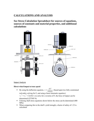
1. CALCULATIONS AND ANALYSIS
See Stress Calculation Spreadsheet for sources of equations,
sources of constants and material properties, and additional
calculations
Impact Analysis
Direct wheel impact at max speed
By using the deflection equation,
EI
Fl
s
192
3
= (based upon two fully constrained
rod ends), solving for F, and using a basic kinematic equation (
)(2
22
savv of ∆== ) to solve for s in terms of F, the force of impact can be
determined (227505 N)
Utilizing shaft stress equations shown below the stress can be determined (400
MPa)
When comparing this to the shaft’s yield strength, a factor of safety of 1.33 is
calculated
2. Direct pulley impact at max speed
Utilizing this same force and finding the stress on the shaft due to bending.
I
Mc
=σ =8510 MPa
This means the shaft will permanently bend due to the moment applied on it
The way to avoid this catastrophic failure is to ensure the chassis protects these
open gears by extending past its edges or enclosing it completely. While this may
not completely ensure the module’s safety, it will fix nearly every probable
scenario.
Shaft Stress Calculations
Shaft 1 (Diameter=3/8”)
• Material: 1045 Steel, Yield Strength (Sy)= 530 MPa, Ultimate Strength= 625MPa
• Max Stress
o The shaft is keyed for a 3/32” key, thus a close approximation for the actual
yield strength is ¾ the materials yield strength (Keyed Yield Strength=398
MPa)
o Loading is comprised of three components
Moment-Based on cantilevered distance from bearing and radial load
exerted on shaft from the miter gear (2.1 N-m)
Force- Based on axial load exerted on shaft from miter gear (156.12
N)
Torque- Exerted by the stall torque of the motor, through a gear ratio
of 2:1 (9.64 N-m)
o Stress Calculation-
2/122
max ]48)8[(
4
TFdM
d
++
Π
=σ =102 MPa
2/122
3max ]64)8[(
2
TFdM
d
++
Π
=τ = 58.4 MPa
o Factors of Safety-
maxσ
yS
n = = 3.9
max2τ
yS
n = = 3.4
• Fatigue Life
o Infinite Life- 2000RPM (Average operating speed)=33.3 cycles/second
5 year life @ 1 hour operating time (2 hr per week)-approximately
1,908,000 seconds of use
33.3*1,908,000=6.4E7 cycles to failure for infinite life
o The endurance strength can be calculated using the stress concentration
factors from the keyway (197 MPa)
o σ’F=Sut+345MPa= 970 MPa
3. o
)2log(
)/'log(
e
eF
N
S
b
σ
−= =-0.109915548
o
b
ut
F
S
f )102(
' 3
⋅=
σ
=.673
o
e
ut
S
Sf
a
2
)( ⋅
= =900 MPa
o Loads are based on typical operating conditions, not max conditions
Moment-Based on cantilevered distance from bearing and radial load
exerted on shaft from the miter gear (2.1 N-m)
Force- Based on axial load exerted on shaft from miter gear (156.12
N)
Torque- Exerted by the operating torque of the motor, through a gear
ratio of 2:1 (2.82 N-m)
o 2/122
3
]48)8[(
4
TFdM
d
a ++
Π
=σ = 39.4 MPa
o b
a
a
N
1
=
σ = 2.25E12 cycles to failure
Shaft 2 (Diameter=1/2”)
• Material: 1045 Steel, Yield Strength= 530 MPa, Ultimate Strength= 625MPa
• Max Stress
o The shaft is keyed for a 1/8” key, thus the actual yield strength can be equated
to ¾ the materials yield strength (Keyed Yield Strength=398 MPa)
o Loading is comprised of three components
Moment-Based on the axle length between bearings and radial load
exerted on shaft from the miter gear (4.28 N-m)
Force- Based on axial load exerted on shaft from miter gear (156.12
N)
Torque- Exerted by the stall torque of the motor, through a gear ratio
of 2:1 (9.64 N-m)
o Stress Calculation-
2/122
max ]48)8[(
4
TFdM
d
++
Π
=σ = 47.2 MPa
2/122
3max ]64)8[(
2
TFdM
d
++
Π
=τ = 26.5 MPa
o Factors of Safety-
maxσ
yS
n = = 8.4
max2τ
yS
n = = 7.5
• Fatigue Life
o Infinite Life- 1000RPM=16.67 cycles/second
4. 5 year life @ 1 hour operating time (2 hr per week)-approximately
1,908,000 seconds of use
16.67*1,908,000=3.2E7 cycles to failure for infinite life
o The endurance strength can be calculated using the stress concentration
factors from the keyway (197 MPa)
o σ’F=Sut+345MPa= 970 MPa
o
)2log(
)/'log(
e
eF
N
S
b
σ
−= =-0.109915548
o
b
ut
F
S
f )102(
' 3
⋅=
σ
=.673
o
e
ut
S
Sf
a
2
)( ⋅
= =900 MPa
o Loads are based on typical operating conditions, not max conditions
Moment-Based on the axle length between bearings and radial load
exerted on shaft from the miter gear (4.28 N-m)
Force- Based on axial load exerted on shaft from miter gear (156.12
N)
Torque- Exerted by the operating torque of the motor, through a gear
ratio of 2:1 (2.82 N-m)
o 2/122
3
]48)8[(
4
TFdM
d
a ++
Π
=σ = 25.6 MPa
o b
a
a
N
1
=
σ = 1.15E14 cycles to failure
Shaft 3 (Diameter=3/4”)
• Material: 1045 Steel, Yield Strength= 530 MPa, Ultimate Strength= 625MPa
• Max Stress
o The shaft is keyed for a 3/16” key, thus the actual yield strength can be
equated to ¾ the materials yield strength (Keyed Yield Strength=398 MPa)
o Loading is comprised of three components
Moment-Based on the axle length between bearings and the force
exerted by the weight of the system (21.53 N-m)
Force- Based on axial load exerted on the shaft from turning forces
(235.44 N)
Torque- Exerted by the stall torque of the motor, through a gear ratio
of 8:1 (38.56 N-m)
o Stress Calculation-
2/122
max ]48)8[(
4
TFdM
d
++
Π
=σ = 59.0 MPa
2/122
3max ]64)8[(
2
TFdM
d
++
Π
=τ = 32.7 MPa
o Factors of Safety-
5.
maxσ
yS
n = = 6.7
max2τ
yS
n = = 6.1
• Fatigue Life
o Infinite Life- 500RPM=8.34 cycles/second
5 year life @ 1 hour operating time (2 hr per week)-apprx 1,908,000
seconds of use
8.34*1,908,000=1.6E7 cycles to failure for infinite life
o The endurance strength can be calculated using the stress concentration
factors from the keyway (197 MPa)
o σ’F=Sut+345MPa= 970 MPa
o
)2log(
)/'log(
e
eF
N
S
b
σ
−= =-0.109915548
o
b
ut
F
S
f )102(
' 3
⋅=
σ
=.673
o
e
ut
S
Sf
a
2
)( ⋅
= =900 MPa
o Loads are based on typical operating conditions, not max conditions
Moment-Based on the axle length between bearings and the force
exerted by the weight of the system (21.53 N-m)
Force- Based on axial load exerted on the shaft from turning forces
(235.4 N)
Torque- Exerted by the operating torque of the motor, through a gear
ratio of 8:1 (11.28 N-m)
o 2/122
3
]48)8[(
4
TFdM
d
a ++
Π
=σ = 35.6 MPa
o b
a
a
N
1
=
σ = 5.7E12 cycles to failure
Steering Shaft (Diameter=1/4”)
• Material: 303 Stainless Steel, Yield Strength= 240 MPa, Ultimate Strength= 620 MPa
• Max Stress
o Loading is based on torque alone (0.745 N-m)
o Stress Calculation-
2/122
max ]48)8[(
4
TFdM
d
++
Π
=σ = 25.7 MPa
2/122
3max ]64)8[(
2
TFdM
d
++
Π
=τ = 14.8 MPa
o Factors of Safety-
maxσ
yS
n = = 9.4
6.
max2τ
yS
n = = 8.1
• Fatigue Life
o σ’F=Sut+345MPa=965E6 MPa
o
)2log(
)/'log(
e
eF
N
S
b
σ
−= =-0.07772
o
b
ut
F
S
f )102(
' 3
⋅=
σ
=.862
o
e
ut
S
Sf
a
2
)( ⋅
= =914 MPa
o Load is comprised of torque alone (.745 N-m)
o 2/122
3
]48)8[(
4
TFdM
d
a ++
Π
=σ = 25.7 MPa
o b
a
a
N
1
=
σ = 9.3E19 cycles to failure
Spur Gears (Calculated using ANSI standards)
Driving Spur
Material- Carbon Steel, Yield Strength=76900 psi, Modulus of Elasticity=30E6
psi, Poisson’s Ratio=.29, Brunell Hardness 179
Max Bending Stress
o
V
H
W t ⋅
=
33000
= 306.8 lbf
o Ko= 1.25 - Overload Factor, based on light shocks encountered
o Kv= 1.15 - Dynamic Factor, based on quality and velocity of gears
o Ks= 1 - Size Factor
o Pd= .833” – Pitch diameter
o F= .25” – face width
o Km= 1.20 – Load-Distribution factor, based on geometry
o KB= 1 – Rim Thickness factor, based on geometry
o J= .325- Geometry factor, based on number of teeth of gears
o
J
KK
F
P
KKKW Bmd
svo
t
=σ =5357.1 psi
o
maxσ
yS
n = = 9.0
Endurance Stress
o
2/1
22
)
11
(
1
−
+
−
=
G
G
p
p
p
E
v
E
v
C
π
=2284.7 lbf/in2
o Cf=1
o I=0.08- Geometry Factor
7. o 2/1
)(
I
C
FP
K
KKWC
f
d
m
so
t
p=σ =56972.4 psi
o Sc= 180000 psi- Repeatedly applied contact strength @ 107
cycles,
material property
o Zn=.59 - Stress cycle life factor, based on hardness and number of cycles
o CH=1 -Hardness ratio factor
o KT= 1- Temperature factor
o KR= 1 – Reliability factor
o
σ
)/( RTHNc
H
KKCZS
S = =1.9
o Comparable factor of safety= SH
2
=3.5
Driven Spur
Material- Carbon Steel, Yield Strength=76900 psi, Modulus of Elasticity=30E6
psi, Poisson’s Ratio=.29, Brunell Hardness 179
Max Bending Stress
o
V
H
W t ⋅
=
33000
= 306.7 lbf
o Ko= 1.25 - Overload Factor, based on light shocks encountered
o Kv= 1.15 - Dynamic Factor, based on quality and velocity of gears
o Ks= 1 - Size Factor
o Pd= 1.667” – Pitch diameter
o F= .25” – face width
o Km= 1.19 – Load-Distribution factor, based on geometry
o KB= 1 – Rim Thickness factor, based on geometry
o J= .389- Geometry factor, based on number of teeth of gears
o
J
KK
F
P
KKKW Bmd
svo
t
=σ =9011.0 psi
o
maxσ
yS
n = = 5.4
Endurance Stress
o
2/1
22
)
11
(
1
−
+
−
=
G
G
p
p
p
E
v
E
v
C
π
=2284.7 lbf/in2
o Cf=1
o I=0.08- Geometry Factor
o 2/1
)(
I
C
FP
K
KKWC
f
d
m
so
t
p=σ = 40010.7 psi
o Sc= 180000 psi- Repeatedly applied contact strength @ 107
cycles,
material property
o Zn=.60 - Stress cycle life factor, based on hardness and number of cycles
o CH=1 -Hardness ratio factor
8. o KT= 1- Temperature factor
o KR= 1 – Reliability factor
o
σ
)/( RTHNc
H
KKCZS
S = = 2.70
o Comparable factor of safety= SH
2
=7.2
Ring/Pinion Gears (Calculated using ANSI standards)
Steering Spur
Material- 2024-T4 Aluminum, Yield Strength=47000 psi, Modulus of
Elasticity=10.4E6 psi, Poisson’s Ratio=.333
Max Bending Stress
o
V
H
W t ⋅
=
33000
= 39.3 lbf
o Ko= 1.25 - Overload Factor, based on light shocks encountered
o Kv= 1.10 - Dynamic Factor, based on quality and velocity of gears
o Ks= 1 - Size Factor
o Pd= .4375” – Pitch diameter
o F= .125” – face width
o Km= 1.20 – Load-Distribution factor, based on geometry
o KB= 1 – Rim Thickness factor, based on geometry
o J= .24- Geometry factor, based on number of teeth of gears
o
J
KK
F
P
KKKW Bmd
svo
t
=σ =951.8 psi
o
maxσ
yS
n = = 44.1
Steering Ring
Material- 2024-T4 Aluminum, Yield Strength=47000 psi, Modulus of
Elasticity=10.4E6 psi, Poisson’s Ratio=.333
Max Bending Stress
o
V
H
W t ⋅
=
33000
= 39.3 lbf
o Ko= 1.25 - Overload Factor, based on light shocks encountered
o Kv= 1.10 - Dynamic Factor, based on quality and velocity of gears
o Ks= 1 - Size Factor
o Pd= 3.125” – Pitch diameter
o F= .125” – face width
o Km= 1.8 – Load-Distribution factor, based on geometry
o KB= 1 – Rim Thickness factor, based on geometry
o J= .4- Geometry factor, based on number of teeth of gears
o
J
KK
F
P
KKKW Bmd
svo
t
=σ = 3996.0 psi
9. o
maxσ
yS
n = = 10.5
Miter Gears (Calculated using ANSI standards)
Both Miters (At max torque)
Material- Medium Carbon Steel, Yield Strength=76900 psi
Max Bending Stress
o Pd= 1.25” – Pitch diameter
o
o
d
t
P
T
W
⋅
=
2
= 84.7 lbf
o Ko= 1.25 - Overload Factor, based on light shocks encountered
o Kv= 1 - Dynamic Factor, based on quality and velocity of gears
o Ks= .5 - Size Factor
o F= .27” – face width
o Km= 1.10 – Load-Distribution factor, based on geometry
o J= 0.175- Geometry factor, based on number of teeth of gears
o Kx= 1, Lengthwise curvature factor
o
JK
KK
KKP
F
W
x
ms
vod
t
=σ =14922.2 psi
o
maxσ
yS
n = = 5.15
Both Miters (At max speed)
Material- Medium Carbon Steel, Yield Strength=76900 psi
Max Bending Stress
o Pd= 1.25” – Pitch diameter
o
o
d
t
P
T
W
⋅
=
2
= 4 lbf
o Ko= 1.25 - Overload Factor, based on light shocks encountered
o Kv= 1.28 - Dynamic Factor, based on quality and velocity of gears
o Ks= .5 - Size Factor
o F= .27” – face width
o Km= 1.10 – Load-Distribution factor, based on geometry
o J= 0.175- Geometry factor, based on number of teeth of gears
o Kx= 1, Lengthwise curvature factor
o
JK
KK
KKP
F
W
x
ms
vod
t
=σ =901.6 psi
o
maxσ
yS
n = = 85.3
Forces
10. o Knowing max torque on miter (9.63 N-m), we can find the max tangential
force by dividing by half the pitch diameter=> Ftan=606.6 N
o α= 20 degress -pressure angle
o d= 45 degrees
o
αcos
tanF
Fn = =645.5 N
o
αsin
1
nF
F = =220.8 N
o dFFF radialaxial sin1== =156.1 N
Retaining Rings
On 3/8” shaft
o Ring can withstand 542.7 N of axial force
o Miter gear provides axial load= 156.1 N
o Factor of safety= 3.48
On 1/2” shaft
o Ring can withstand 542.7 N of axial force
o Miter gear provides axial load= 156.1 N
o Factor of safety= 3.48
On 3/4” shaft
o Ring can withstand 631.6 N of axial force
o Axial load is from turning
Assume wheel instantaneously turns 90 degrees, the max force that
can be applied axially would be equivalent to the frictional force
µ⋅== WFF frictionaxial =235.4 N (assuming µ=.6)
o Factor of safety= 2.68
Mechanical Brake
Max Temperature
Assuming all kinetic energy is converted directly into heat energy,
TCmvm vplatevehveh ∆=
2
2/1
Assume emergency brake will not be used continuously, but rather for one cycle
during the emergency
Assume initial temperature of 23 ° Celcius
Solving the above equation for Tfinal we find it to be 38.9 °Celcius
Heat Dissipation
Assuming Free Convection, the time required for heat dissipation can be
calculated
Utilizing the properties of air at room temperature, the Rayleigh number, Nusselt
number, and convection heat transfer coefficient can be calculated
11. Using this information the heat transfer rate is determined
q
E
t
∆
=∆ gives the time to dissipate the heat (4.8 minutes)
This resultant was later verified by the manufacturer of the brake
Keys
On 3/8” Shaft
Key is High carbon steel, Yield Strength 427 MPa, 3/32” square
Knowing the diameter of and torque on the shaft, the shear force on the key can
be calculated (2024.1 N)
Assuming a factor of safety of 4, the required length of the key is calculated
(.63”)
On 1/2” Shaft
Key is High carbon steel, Yield Strength 427 MPa, 1/8” square
Knowing the diameter of and torque on the shaft, the shear force on the key can
be calculated (1518.1 N)
Assuming a factor of safety of 4, the required length of the key is calculated
(.35”)
On 3/4” Shaft
Key is High carbon steel, Yield Strength 427 MPa, 3/16” square
Knowing the diameter of and torque on the shaft, the shear force on the key can
be calculated (4048.3 N)
Assuming a factor of safety of 4, the required length of the key is calculated
(.63”)
Keyways
• Keyway analysis was done using Cosmos FEA software
• By utilizing shaft diameters and torques, forces on keyway surfaces were
calculated and input into the program
• Factor of Safety
o Driving Miter=16
o Driven Miter=15
o Driving Pulley=3.4
o Driven Pulley=8.4
o Driven Spur=8.1
o Wheel=1.8, but in reality, failure would result in the slip of a pressed
insert, rather than physical failure of the wheel
Set Screws
To connect spur gear to 5/16” drive motor shaft
By choosing a screw size and quantity (2- #8’s), the maximum force at the shaft
surface can be calculated (3425.1 N)
12. The torque and diameter of the shaft is used to determine the actual force seen at
this shaft surface (1214.5 N)
By comparing these two values the factor of safety is determined (2.82)
To connect spur gear to 8mm steering motor shaft
By choosing a screw size and quantity (2-#6’s), the maximum force at the shaft
surface can be calculated (2224.1 N)
The torque and diameter of the shaft is used to determine the actual force seen at
this shaft surface (234.6 N)
By comparing these two values the factor of safety is determined (9.5)
Timing Belt and Pulleys
• Utilizing MITCalc simulation software and inputting various parameters
including distance between centers, power applied to belt, operating
speeds, and other operating conditions a belt type and specific model was
selected
• From this the 5M Powergrip GT2 belt was chosen and matched with
pulleys of 18 and 72 teeth
• The selection of these parts was also verified with an engineer at the
supplier sdp-si.com
Bearings
C10 = Catalog Load Rating (lbf)
LR = Rating Life (hrs)
nR = Rating Speed (RPM)
FD = Desired Radial Load (lbf)
LD = Desired Life (hrs)
nD = Desired Speed (RPM)
FR = Radial Force (lbf)
FA = Axial Force (lbf)
Fe = Equivalent Radial Load (lbf)
C0 = Static Load Rating (lbf)
X2 = Factor dependent on bearing geometry
Y2 = Factor dependent on bearing geometry
V = Rotation Factor
a = 3 (ball bearing)
e = abscissa
Lower Drive Bearing
C10 (lbs) 1171 Upper Drive Bearing Center Bearing
LR * nR 1.0E+06 C10 (lbs) 1187 C10 (lbs) 691
FD (lbs) 44.125 LR * nR 1.0E+06 LR * nR 1.0E+06
nD (RPM) 5.0E+02 Fe (lbs) 84.6 Fe (lbs) 70.6
a 3 nD (RPM) 2000 nD (RPM) 4000
13. ARe
D
RR
a
D
D
FYVFXF
n
nL
F
C
L
22
10 *
+=
=
LD (hrs) 3.74E+07 FA (lbs) 35.1 FA (lbs) 35.1
LD (years) 4267 FR (lbs) 35.1 FR (lbs) 35.1
a 3 a 3
Steering Bearing V 1 V 1
C10 (lbs) 300 e 0.24 e 0.3
LR * nR 1.0E+06 X2 0.56 X2 0.56
FD (lbs) 10 Y2 1.85 Y2 1.45
nD (RPM) 340 LD (hrs) 1.38E+06 LD (hrs) 2.34E+05
a 3 LD (years) 158 LD (years) 27
LD (hrs) 7.94E+07
LD (years) 9065
Screws
Bolts connecting Yoke to Turntable
Bolt type: 4 * 10-32 (SAE)
Torque applied to the turntable
T= 2.38 N-m
Converted ASTM
T = 21 lb-in
Resultant load on each bolt
lb
in
inlb
r
T
V 108.8
59.2
1
*21 =−==
inlbTM −== 21
Primary Shear Load per Bolt is
lb
n
V
F 027.2
4
108.8
' ===
Since the secondary shear Forces are equal we have
lb
r
M
r
Mr
F 027.2
59.2*4
21
44
'' 2
====
The resultant force is
14. lbFr 867.2=
Fr = Fa = Fb = Fc = Fd = 2.867lb
Maximum Shear Stress
As = 0.155
psi
A
F
s
r
497.18
155.
867.2
===τ
Bolts connecting Brake to Brake plate
Bolt type: 4 * 8-32 (SAE)
Torque applied to the turntable
T = 15 lb-in
Resultant load on each bolt
lb
in
inlb
r
T
V 33.13
125.1
1
*15 =−==
inlbTM −== 15
Primary Shear Load per Bolt is
lb
n
V
F 33.3
4
33.13
' ===
Since the secondary shear Forces are equal we have
lb
r
M
r
Mr
F 33.3
125.1*4
15
44
'' 2
====
The resultant force is
lbFr 714.4=
Fr = Fa = Fb = Fc = Fd = 4.714 lb
15. Maximum Shear Stress
As = .0992
psi
A
F
s
r
9.28
0992.
867.2
===τ
Yoke
• Yoke stress analysis was done using Cosmos FEA software
• Loading
o Weight vertically loads lower bearing holes (196.2 N each)
o Turning force loads inside wall (158.3 N)
o Driven Miter axial force loads inside wall (156 N)
o Driven Miter radial force loads upper bearing holes
o Driving Miter axial force loads upward on top plate
16. • Minimum factor of safety= 20
Brake Plate
• Brake plate stress analysis was done using Cosmos FEA software
• Loading
o Outside edge was fixed, as it is welded to the motor mount assembly
o Each brake mounting hole was loaded with a force corresponding to the
brake’s torque output and the holes distance from center
• Minimum factor of safety= 200
Turntable
• Capable of withstanding 750 lbs, or 340 kg
• Actual weight is about 40 kg per module
• Factor of Safety= 8.5
17. Figure X: Shaft Stress and Fatigue Strength Calculations
Figure X: Drive Motor Spur Gear Stress Calculation
18. Figure X: Miter Gear Stress and Force Calculation
Figure X: Retaining Ring Calculations Figure X: Impact Calculations
Figure
X:
Brake
Temperature and Heat Dissipation Calculations
23. Figure X: Driven Spur Gear Keyway Analysis
Figure X: Wheel Keyway Analysis (Representation)
Note: Actual wheel utilizes press fit keyway insert, thus failure during stall will result in
slip of this insert, rather than the physical failure of a mechanical part
![Direct pulley impact at max speed
Utilizing this same force and finding the stress on the shaft due to bending.
I
Mc
=σ =8510 MPa
This means the shaft will permanently bend due to the moment applied on it
The way to avoid this catastrophic failure is to ensure the chassis protects these
open gears by extending past its edges or enclosing it completely. While this may
not completely ensure the module’s safety, it will fix nearly every probable
scenario.
Shaft Stress Calculations
Shaft 1 (Diameter=3/8”)
• Material: 1045 Steel, Yield Strength (Sy)= 530 MPa, Ultimate Strength= 625MPa
• Max Stress
o The shaft is keyed for a 3/32” key, thus a close approximation for the actual
yield strength is ¾ the materials yield strength (Keyed Yield Strength=398
MPa)
o Loading is comprised of three components
Moment-Based on cantilevered distance from bearing and radial load
exerted on shaft from the miter gear (2.1 N-m)
Force- Based on axial load exerted on shaft from miter gear (156.12
N)
Torque- Exerted by the stall torque of the motor, through a gear ratio
of 2:1 (9.64 N-m)
o Stress Calculation-
2/122
max ]48)8[(
4
TFdM
d
++
Π
=σ =102 MPa
2/122
3max ]64)8[(
2
TFdM
d
++
Π
=τ = 58.4 MPa
o Factors of Safety-
maxσ
yS
n = = 3.9
max2τ
yS
n = = 3.4
• Fatigue Life
o Infinite Life- 2000RPM (Average operating speed)=33.3 cycles/second
5 year life @ 1 hour operating time (2 hr per week)-approximately
1,908,000 seconds of use
33.3*1,908,000=6.4E7 cycles to failure for infinite life
o The endurance strength can be calculated using the stress concentration
factors from the keyway (197 MPa)
o σ’F=Sut+345MPa= 970 MPa](data:image/gif;base64,R0lGODlhAQABAIAAAAAAAP///yH5BAEAAAAALAAAAAABAAEAAAIBRAA7)