Belt drives extra
•
3 likes•4,461 views

This document is about power transmission system. It's aimed those interested in learning about mechanical engineering and students who are studying various programmes in engineering. This document only deals with power transmission through flat and v-belts.

Recommended
More Related Content
What's hot
What's hot (20)
Similar to Belt drives extra
Similar to Belt drives extra (20)
Recently uploaded
Recently uploaded (20)
Belt drives extra
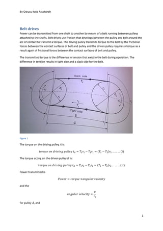
- 1. By Owusu Kojo Attakorah 1 Belt drives Power can be transmitted from one shaft to another by means of a belt running between pulleys attached to the shafts. Belt drives use friction that develops between the pulley and belt around the arc of contact to transmit a torque. The driving pulley transmits torque to the belt by the frictional forces between the contact surfaces of belt and pulley and the driven pulley requires a torque as a result again of frictional forces between the contact surfaces of belt and pulley. The transmitted torque is the difference in tension that exist in the belt during operation. The difference in tension results in tight side and a slack side for the belt. Figure 1 The torque on the driving pulley 𝐴 is: 𝑡𝑜𝑟𝑞𝑢𝑒 𝑜𝑛 𝑑𝑟𝑖𝑣𝑖𝑛𝑔 𝑝𝑢𝑙𝑙𝑒𝑦 𝑡 𝐴 = 𝑇1 𝑟1 − 𝑇2 𝑟1 = (𝑇1 − 𝑇2)𝑟1 … … … (𝑖) The torque acting on the driven pulley 𝐵 is: 𝑡𝑜𝑟𝑞𝑢𝑒 𝑜𝑛 𝑑𝑟𝑖𝑣𝑖𝑛𝑔 𝑝𝑢𝑙𝑙𝑒𝑦 𝑡 𝐵 = 𝑇1 𝑟2 − 𝑇2 𝑟2 = (𝑇1 − 𝑇2)𝑟2 … … … (𝑖𝑖) Power transmitted is 𝑃𝑜𝑤𝑒𝑟 = 𝑡𝑜𝑟𝑞𝑢𝑒 ×𝑎𝑛𝑔𝑢𝑙𝑎𝑟 𝑣𝑒𝑙𝑜𝑐𝑖𝑡𝑦 and the 𝑎𝑛𝑔𝑢𝑙𝑎𝑟 𝑣𝑒𝑙𝑜𝑐𝑖𝑡𝑦 = 𝑣 𝑟1 for pulley 𝐴, and
- 2. 𝑎𝑛𝑔𝑢𝑙𝑎𝑟 𝑣𝑒𝑙𝑜𝑐𝑖𝑡𝑦 = 𝑣 𝑟2 for pulley 𝐵, 𝑣 being the belt speed, then for either pulley: 𝑃 = (𝑇1 − 𝑇2)𝑣 … … … (1) Angle of lap The term angle of lap is used for the angle subtended at the centre of a pulley by the contact length of the belt with pulley wheel. In figure 1 these angles are 𝜃1 and 𝜃2. Types of pulleys The rims of may be flat or V-grooved. Belt may be flat, i.e. of rectangular section, or of wedge section i.e. V-shaped belt, or circular (these being referred to as ropes). Advantages Compared with gear systems as a means of transmitting power between shafts, belt drives have several advantages. Belt drives are automatically protected against overload because slipping occurs if the loading exceeds the maximum tension that can be sustained by the frictional forces. The length of belt can easily be adapted to suit a wide range of shaft centre distances. Different size pulleys may be used to a give a gearing effect. Disadvantages There are however, some disadvantages. The speed ratio is generally limited to about 3:1 because of the need to maintain an adequate arc of contact between belt and pulley. Repeated flexing of the belt running on to and off the pulleys results in fatigue of the material. Belts stretch during operation and consequently alter the relationship between tension, speed and torque. Flat pulley drives Consider a flat belt passing round a flat pulley so that the angle of lap is 𝜃 and the tensions in the belt arc are 𝑇1 and 𝑇2 when it is just on the point of slipping. 𝑇1 − 𝑚𝑣2 𝑇2 − 𝑚𝑣2 = 𝑒 𝜇𝜃 … … … … (2) In equation (2) 𝑚𝑣2 is sometimes referred to as the centrifugal or centripetal tension. It has the effect of reducing the tension available for transmitting power. Under low speed conditions 𝑚𝑣2 can be neglected to give: 𝑇1 𝑇2 = 𝑒 𝜇𝜃 … … … (3) Power transmission From eqn (1) the power transmitted by the belt is given by: 𝑃 = (𝑇1 − 𝑇2)𝑣 … … … (𝑎) Which becomes, when 𝑚𝑣2 is not neglected and using eqns (1) and (2):
- 3. By Owusu Kojo Attakorah 3 𝑃 = (𝑇1 − 𝑇1 − 𝑚𝑣2 𝑒 𝜇𝜃 − 𝑚𝑣2 ) 𝑣 𝑃 = (𝑇1 − 𝑚𝑣2)(1 − 𝑒−𝜇𝜃 )𝑣 … … … (4) And when 𝑚𝑣2 is neglected and eqns (1) and (3) are used: 𝑃 = 𝑇1(1 − 𝑒−𝜇𝜃 )𝑣 … … … (5) Belt drive design requirements In order to select a drive belt and its associated pulley assemblies for a specified use, and to ensure proper installation of the drive, several important factors need to be considered. The basic data required for drive selection is listed below: Rated power of the driving motor or other prime mover The service factor, which is dependent on the time in use, operating environment and the type of duty performed by the drive system Belt power rating Belt length Size of driving and driven pulleys and centre distance between pulleys Correction factors for belt length and lap angle on smaller pulley Number of belts Initial tension on belt. Provision must be made for belt adjustment and pre-tensioning, so the distance between pulley centres must be adjustable.
- 4. 𝐷 – diameter of lager pulley 𝑑 – diameter of smaller pulley 𝜃1- Angle of lap of the larger pulley 𝜃2- Angle of lap of the larger pulley 𝐶 - centre distance between the two pulleys. Basic formulae 𝜃1 = 180 − 2𝛽 𝜃2 = 180 + 2𝛽 𝛽 = sin−1 ( 𝑅−𝑟 𝐶 ) or 𝛽 = sin−1 ( 𝐷−𝑑 2𝐶 ), where R is radius of the larger puller and r is radius of smaller pulley. 𝐿 𝑜 − length of open belt 𝐿 𝑜 = 𝜋 2 (𝐷 + 𝑑) + 2𝐶 + 1 4𝐶 (𝐷 − 𝑑)2 or 𝐿 𝑜 = 2√ 𝐶2 − ( 𝐷 − 𝑑 2 ) 2 + 𝜃1 𝑟1 + 𝜃2 𝑟2 Or 𝐿 𝑜 = 2𝐶 cos 𝛽 + 𝜃1 𝑟1 + 𝜃2 𝑟2 S – span length between centres 𝑆 = 𝐶 cos 𝛽 Or 𝑆 = √ 𝐶2 − ( 𝐷 − 𝑑 2 ) 2 Example Two pulleys, one of diameter 150 mm and the 200 mm, are on parallel shafts with centres 600 mm apart. What is the angle of contact between a flat belt and each pulley? What power can be transmitted when the larger pulley rotates at 300 rev/min if the maximum tension in the belt is to be 1 kN and coefficient of friction between belt and pulley is 0.25? The figure below shows the arrangement. 𝛽 = sin−1 ( 25 600 ) = 2.39°
- 5. By Owusu Kojo Attakorah 5 Let 𝜃 𝐴 be the lap angle for the small pulley, therefore: 𝜃 𝐴 = 180 − 2×2.39°3,58° = 175.22° = 3.06 𝑟𝑎𝑑 The angle of lap of pulley 𝐵 is: 𝜃 𝐵 = 180 + 2𝛽 = 184.78° = 3.23 𝑟𝑎𝑑 From equation (5) we have: 𝑃 = 𝑇1(1 − 𝑒−𝜇𝜃 )𝑣 For the larger pulley 𝑣 = 𝜔𝑟 = 0.1×2𝜋×5 = 3.14 𝑚/𝑠 The maximum tension 𝑇1 = 1 𝑘𝑁 The maximum power will depend on the angle of lap of the smaller pulley. This is because the length of belt in contact with the pulley is the smallest and slip will thus occur there before occurring at the larger pulley. Thus 𝑃 = 1×10³(1 − 𝑒−0.25×3.06)×3.14 = 1.68 𝑘𝑊 Example A flat belt is required to transmit 100 kW at a belt speed of 20 m/s between two pulleys of diameters 250 mm and 400 mm when the distance between the pulley centres is 1200 mm. The material to be used for the belt has a maximum permissible stress of 0.8 MPa and is available in thickness to width ratios of 1 to 10. The belt material has a density of 1100 kg/m3 with a coefficient of friction between it and the pulleys of 0.30. What is the maximum belt thickness that can be used? 𝛽 = sin−1 ( 75 1200 ) = 3.58° The angle of lap of the smaller pulley is given by 𝜃 𝐴 = 180 − 2×3,58° = 172.84° = 3.02 𝑟𝑎𝑑 The maximum tension 𝑇1 = 0.8×10⁶ ×𝐴, where 𝐴 is the cross-sectional area of the belt. If the thickness is 𝑡 then, since the width is 10𝑡, the area is 10𝑡2 . 𝑡 𝑤
- 6. Thus from eqn (4) 𝑃 = (𝑇1 − 𝑚𝑣2)(1 − 𝑒 − 𝜇𝜃 )𝑣 … … … (4) 𝑃 = 100×103 = (0.8×106 ×10𝑡2 − 1100×10𝑡2 ×202 )(1 − 𝑒 −0.25×3.02)×20 Hence 𝑡 = 10.3 𝑚𝑚 Initial tension Let 𝑇𝑜 be the initial static tension in the belt. When the pulley is running then the tension on the tight side becomes 𝑇1 and that on the slack side 𝑇2. If we assume that the material is elastic and obeys Hooke’s law then if the overall length of the belt remains unchanged, the increase in length of the slack side must be balanced by the reduction in length of the tight side. Since the change in length of the belt material will be proportional to the change in tension we must therefore have: 𝑇1 − 𝑇𝑜 = 𝑇𝑜 − 𝑇2 and 𝑇0 = 1 2 (𝑇1 + 𝑇2) … … … (6) Example A flat belt is installed with an initial tension of 400 N. The coefficient of friction between the belt and pulley is 0.3 and the angle of lap on the smaller pulley is 165°. The smaller pulley has a diameter of 100 mm and rotates at 600 rev/min. Determine the maximum power which the belt can transmit if it is assumed to have negligible mass. From equation (6) the relationship between the initial tension and tensions of the slack and tight sides of the belt is: 𝑇0 = 1 2 (𝑇1 + 𝑇2) = 400 … … … (𝑎) The negligible mass condition means that the centripetal tension can be neglected. From equation (3) we have: 𝑇1 𝑇2 = 𝑒 𝜇𝜃 = 𝑒03×2.88 = 2.37 As 𝜃 = 165° = 2.88 𝑟𝑎𝑑 and hence 𝑇1 = 2.37𝑇2 … … … (𝑏) From equations (a) and (b) we have: 400 = 1 2 (2.37𝑇2 + 𝑇2)
- 7. By Owusu Kojo Attakorah 7 𝑇2 = 237.4 𝑁 And 𝑇1 = 562.6 𝑁 From eqn (1) we have: 𝑃 = (𝑇1 − 𝑇2)𝑣 = (562.6 − 237.4)0.05×2𝜋×10 = 1.02 𝑘𝑊 Maximum power transmission The equation for the initial static tension [eqn (6)] 𝑇0 = 1 2 (𝑇1 + 𝑇2) Can be written, by subtracting 2𝑚𝑣2 from both sides, as 2𝑇0 − 2𝑚𝑣2 = (𝑇1 − 𝑚𝑣2 + 𝑇2 − 𝑚𝑣2) … … … (𝑐) From eqn (2) 𝑇2 − 𝑚𝑣2 = 𝑇1 − 𝑚𝑣2 𝑒 𝜇𝜃 … … … (𝑑) From eqns (c) and (d) we have: 2𝑇0 − 2𝑚𝑣2 = (𝑇1 − 𝑚𝑣2 + 𝑇1 − 𝑚𝑣2 𝑒 𝜇𝜃 ) Hence 𝑇1 − 𝑚𝑣2 = 2(𝑇0 − 𝑚𝑣2 ) 1 + 𝑒 𝜇𝜃 … … … (𝑑) From eqns (4) and (d) 𝑃 = 2(𝑇0 − 𝑚𝑣2 )( 1 − 𝑒−𝜇𝜃 1 + 𝑒 𝜇𝜃 )𝑣 … … … (7) The maximum power for a given setting of 𝑇0 is when 𝑑𝑃 𝑑𝑣 = 0 This is thus when
- 8. 𝑇0 − 3𝑚𝑣2 = 0 Since the centripetal tension is 𝑚𝑣2 , maximum power is when the static initial tension is three times the centripetal tension. The above equation can be written as: 𝑣 = √ 𝑇0 3𝑚 … … … (8) The maximum belt tension occurs when: 𝑣 = 0, 𝑖. 𝑒. 𝑤ℎ𝑒𝑛 𝑡ℎ𝑒 𝑐𝑒𝑛𝑡𝑟𝑖𝑝𝑒𝑡𝑎𝑙 𝑡𝑒𝑛𝑠𝑖𝑜𝑛 𝑖𝑠 𝑧𝑒𝑟𝑜, i.e. when the centripetal tension is zero. Example A flat belt having a mass of 0.2 kg/m is used to transmit power between two pulleys of diameters 100 mm and 200 m, the distance between their centres being 1000 mm. If the maximum permissible belt tension is 500 N and the coefficient of friction is 0.3, at what belt speed will the power transmitted be a maximum? 𝛽 = sin−1 50 1000 = 2.86° The angle of lap of the smaller pulley is given by 𝜃 𝐴 = 180 − 2×2.86° = 174.28° = 3.04 𝑟𝑎𝑑 The maximum tension is determined by this angle of lap on the smaller pulley. The maximum tension occurs when the centripetal tension is zero and is then: 𝑇1 = 500 𝑁 Thus 𝑇1 𝑇2 = 𝑒 𝜇𝜃 = 𝑒03×3.04 = 2.49 𝑇2 = 500 2.49 = 200.8 𝑁 𝑇0 = 1 2 (𝑇1 + 𝑇2) = 1 2 (500 + 200.8) = 350.4 𝑁 The maximum belt speed is thus given by equation (8) 𝑣 = √ 𝑇0 3𝑚 = √ 350.4 3×0.2 = 24.2 𝑚/𝑠 V-pulley drives
- 9. By Owusu Kojo Attakorah 9 The V has an angle of 2𝛼. The normal reaction in each face of an element is 𝑁. The component of these reactions at right angles to the belt, i.e. the radial reaction component 𝑅, is 𝑅 = 2𝑁 sin 𝛼 The frictional force is 2𝜇𝑁. Hence we can write: 𝐹𝑟𝑖𝑐𝑡𝑖𝑜𝑛 𝑓𝑜𝑟𝑐𝑒 = 2𝜇𝑁 = 𝜇𝑅 sin 𝛼⁄ Thus in the equations obtained for the flat pulley drive above, we need to replace 𝜇 by 𝜇 sin 𝛼⁄ to obtain the equations for V-pulley drives. The same result is obtained for circular cross-section rope in a V-shaped groove. Example A V-belt is used to transmit power between two pulleys of diameters 100 mm and 200 mm, the distance between their centres being 1000 mm. The groove angle is 40° and the coefficient of friction 0.3. If the maximum permissible tension is 400 N, what power can be transmitted if the larger pulley is driven at 600 rev/min? 𝛽 = sin−1 50 1000 = 2.86° The angle of lap of the smaller pulley is given by 𝜃 𝐴 = 180 − 2×2.86° = 174.28° = 3.04 𝑟𝑎𝑑 The maximum tension is determined by this angle of lap on the smaller pulley. Using equation (3) and replacing 𝜇 sin 𝛼⁄ for 𝛼 we have: 𝑇1 𝑇2 = 𝑒 𝜇𝜃 sin 𝛼⁄ = 𝑒03×3.04/ sin20° = 14.39 𝐺𝑟𝑜𝑜𝑣𝑒 𝑎𝑛𝑔𝑙𝑒 = 2𝛼 = 40° Therefore 𝛼 = 20° The maximum tension will be 𝑇1. Thus 𝑇2 = 400 14.39 = 27.8 𝑁 The power transmitted is given by: 𝑃 = (𝑇1 − 𝑇2)𝑣 = (400 − 27.8)0.1×2𝜋×10 = 23.4 𝑘𝑊
- 10. Reference: Bolton, W. (1999) High Engineering Science. Oxford Bird, J. & Ross, C. (2002) Mechanical Engineering Principles. Oxford Darbyshire, A. (2008) Mechanical Engineering 2nd Ed. BTEC National Engineering Specialist Units. Oxford. Tooley, M. & Dingle, L. (2004) Higher National Engineering 2nd Ed. Oxford Bolton, W. (2006) Mechanical Science 3rd Ed. Blackwell Publishers, Oxford