Download as PDF, PPTX

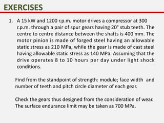
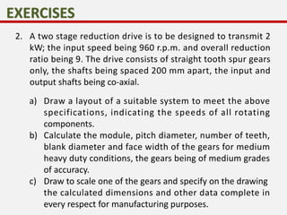


This problem involves designing a gear drive system to meet specific power, speed, and ratio requirements. 1. The key specifications are: 15 kW power at 1200 rpm driving a compressor at 300 rpm, with a gear ratio of 4:1. The shafts are 400mm apart. The pinion is forged steel with 210 MPa allowable stress, and the gear is cast steel with 140 MPa stress. 2. A two-stage gear train layout is proposed to achieve a 9:1 ratio from an input of 960 rpm to transmit 2 kW power. The shafts are 200mm apart with coaxial input/output. 3. The solution involves calculating the module, pitch diameter, number


![[IJET V2I3P8] Authors: Pravin B. Sonawane, P.G.Damle](https://cdn.slidesharecdn.com/ss_thumbnails/ijet-v2i3p8-160609052616-thumbnail.jpg?width=640&height=640&fit=bounds)


