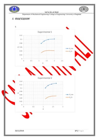
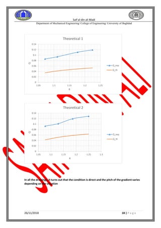
SlideShare a Scribd company logo
Saif al-din ali Madi
Department of Mechanical Engineering/ College of Engineering/ University of Baghdad
26/11/2018 1 | P a g e
[power plant Laboratory II]
University of Baghdad
Name: - Saif Al-din Ali -B-
Saif al-din ali Madi
Department of Mechanical Engineering/ College of Engineering/ University of Baghdad
26/11/2018 2 | P a g e
TABLE OF CONTENTS
Objective............................................................................I
INTRODUCTION.............................................................II
THEORY.........................................................................III
Calculations and results..................................................V
DISCUSSION..................................................................VI
Saif al-din ali Madi
Department of Mechanical Engineering/ College of Engineering/ University of Baghdad
26/11/2018 3 | P a g e
Experiment Name:-
1. Objective
2. Introduction
Two types of nozzles: -
1. Converging-Diverging or " De Laval" Nozzles have been widely used over the last few
decades in many engineering contexts, from civil and mechanical to aerospace uses. They are
designed to accelerate fluids to supersonic speeds at the nozzle exit. Nearly all rockets make
use of this fact to create an effective propulsion system to reach high velocities. Whilst their
operation is of a simple appearance, the combination of flows reached, be that subsonic and
supersonic and the subsequent change of properties such as pressure, density and temperature
make the underlying investigation of their performance more complicated than first expected.
Their operation relies on the ratio between the inlet stagnation pressure P0 and outlet back pressure
Pb. As this ratio Pb/Po is brought down from unity, the mass flow rate increases till a maximum
value is achieved where the Mach number in the throat (see Figure 1) becomes sonic.
( Mach no = 1). This is referred to as "Choked flow". As the ratio is further decreased the flow
becomes supersonic in the diverging nozzle, till the design pressure ratio is achieved (0.53 for air)
with supersonic flow occurring at the nozzle exit. After this the flow becomes more complicated
and normal and oblique shock waves begin to occur inside and outside of the nozzle respectively.
The Purpose of this report is to gain an understanding of the nature of this flow by
investigating the pressure ratios effects on the mass flow rate of air through the system and the
differing pressure distributions that occur at varying lengths into the nozzle.
Figure 1. Schematic of a converging-diverging nozzle
2. converging nozzle
Saif al-din ali Madi
Department of Mechanical Engineering/ College of Engineering/ University of Baghdad
26/11/2018 4 | P a g e
Converging nozzles, as shown in Figure 2, are tubes with an area that decreases from the
nozzle entry to the exit (or throat) of the nozzle. As the nozzle area decreases, the flow
velocity increases, with the maximum flow velocity occurring at the nozzle throat. As the
inlet flow velocity is increased, flow velocity at the nozzle throat keeps increasing until it
reaches Mach 1. At this point, the flow at the throat gets choked, meaning that any further
increase of inlet flow velocity will not increase the flow velocity at the throat. It is for this
reason that converging nozzles are used to accelerate fluids in the subsonic flow regime
alone and can commonly be found on all commercial jets (except for the Concord) as they
travel at subsonic speeds.
Figure 2. Schematic of a converging nozzle
3. divergent nozzle
represents a divergent nozzle for a fluid whose peculiarity is that — decreases with
the drop of pressure, i.e., specific volume increases at a faster rate than velocity
with the drop of pressure. The area of cross-section should increase as the
pressure decreases.
Figure 3. diverging nozzle
the flow conditions that can be observed in a converging nozzle:
1. No flow condition, where the back-pressure is equal to the total pressure.
2. Subsonic flow, where the flow accelerates as area decreases, and the pressure
drops.
3. Subsonic flow, where there is significantly higher acceleration and the pressure
drops.
4. Choked flow, where any pressure drop does not accelerate the flow.
5. Choked flow, where the flow expands after the nozzle exit (considered non-
isentropic).
Saif al-din ali Madi
Department of Mechanical Engineering/ College of Engineering/ University of Baghdad
26/11/2018 5 | P a g e
Figure 4. Flow conditions and regimes in a converging nozzle (theoretical predictions)
converging-diverging nozzle shows the following seven profiles in the position
versus pressure ratio plot. Note that the first vertical dashed line on the left of the
p/pO versus distance along the nozzle plot is the location of the throat, the second
vertical dashed line is the location of the nozzle exit, and the horizontal dashed line
marks the choked condition.
1. Subsonic flow that never reaches choked condition.
2. Subsonic flow that reaches choked condition but does not attain supersonic velocities
(considered isentropic).
3. Subsonic flow that reaches choked condition, with the resulting supersonic flow forming a
normal shock, which then experiences subsonic deceleration. Here, the normal shock
causes a sudden drop in velocity and an increase in back-pressure, as indicated by the
sudden increase in p/pO.
4. Subsonic flow that reaches choked condition, with the resulting supersonic flow forming a
normal shock after the nozzle (considered isentropic in the nozzle).
5. Over-expanded flow – the pressure at the nozzle exit is lower than the ambient pressure,
causing the jet exiting the nozzle to be highly unstable with huge variations in pressure
and velocity as it travels downstream.
6. Flow after the choked condition is supersonic through the nozzle, and no shock is formed.
7. Under-expanded flow – the pressure at the nozzle exit is higher than the ambient pressure
and results in similar effects as over-expanded flow.
Figure 5. Flow conditions and regimes in a converging-diverging nozzle (theoretical
predictions)
3. Theory
Saif al-din ali Madi
Department of Mechanical Engineering/ College of Engineering/ University of Baghdad
26/11/2018 6 | P a g e
The characteristic of a nozzle can be graphically represented by diagram which
shows the mass flow rate through the nozzle related to the downstream pressure
outlet, with fluid conditions maintained constant upstream of the nozzle. In
subsonic nozzle conditions the flow rate can be expressed by:
𝑸𝒕𝒉 = 𝑨𝒖 ∗
𝒑 𝟎
√ 𝒑 𝟎 ∗ 𝒗
∗ √
𝟐𝒌
𝒌 − 𝟏
∗ [(
𝒑 𝐛
𝒑 𝟎
)
𝟐
𝒌
− (
𝒑 𝐛
𝒑 𝟎
)
𝒌+𝟏
𝒌
]
𝑨 𝒖 =
𝝅
𝟒
𝑫 𝒕𝒉
𝟐
Where:
Po = Total pressures upstream the nozzle,
Vo=Specific volume upstream the nozzle
Au= the narrow outlet section of the nozzle (throat).
P2 = Pressure downstream the nozzle,
K = Specific heat ratio (taken l for temperature 170 ° C)
For critical pressure downstream the nozzle the mass flow rate will be max (i.e.) the
nozzle is chocked can be calculated as:
𝑸 𝒎 𝒂𝒙
= 𝑨 𝒖
𝒑 𝟎
√ 𝒑 𝟎 𝝂 𝟎
∗ √
𝟐𝒌
𝒌 − 𝟏
𝑸 𝐞𝐱𝐩 = 𝒌√
𝜟𝒑
𝒗 𝒐
Saif al-din ali Madi
Department of Mechanical Engineering/ College of Engineering/ University of Baghdad
26/11/2018 7 | P a g e
4. Calculations and results
𝑨 𝒖 =
𝝅
𝟒
𝑫 𝒕𝒉
𝟐
= (
3.14
4
) ∗ (8 ∗ 10−3)2
= 5.03 ∗ 10−5
𝑚2
1.
𝑸𝒕𝒉 = 𝑨𝒖 ∗
𝒑 𝟎
√ 𝒑 𝟎 ∗ 𝒗
∗ √
𝟐𝒌
𝒌 − 𝟏
∗ [(
𝒑 𝐛
𝒑 𝟎
)
𝟐
𝒌
− (
𝒑 𝐛
𝒑 𝟎
)
𝒌+𝟏
𝒌
]
𝑸𝒕𝒉 = 𝟓. 𝟎𝟑 ∗ 𝟏𝟎−𝟓
∗
𝟒 ∗ 𝟏𝟎 𝟓
√𝟒 ∗ 𝟏𝟎 𝟓 ∗ 𝟎. 𝟒𝟔𝟒𝟐𝟓𝟏
∗ √
𝟐 ∗ 𝟏. 𝟏𝟒
𝟏. 𝟏𝟒 − 𝟏
∗ [(
𝟑. 𝟓 ∗ 𝟏𝟎 𝟓
𝟒 ∗ 𝟏𝟎 𝟓
)
𝟐
𝟏.𝟏𝟒
− (
𝟑. 𝟓 ∗ 𝟏𝟎 𝟓
𝟒 ∗ 𝟏𝟎 𝟓
)
𝟏.𝟏𝟒+𝟏
𝟏.𝟏𝟒
]
𝑸𝒕𝒉 = 𝟎. 𝟎𝟑𝟏𝟏𝟐𝟏𝟖 𝐦 𝟑
/𝒉
𝑸 𝐞𝐱𝐩 = 𝒌√
𝜟𝒑
𝒗 𝒐
𝑸 𝐞𝐱𝐩 = 𝟓. 𝟔𝟏𝟓√
𝟗𝟏.𝟐
𝟎.𝟒𝟔𝟒𝟐𝟓
= 𝟎. 𝟎𝟕𝟖𝟔𝟗𝟗
𝒎 𝟑
𝒉𝒓
𝑹 = 𝑷𝒐/𝑷𝒃
𝑹 = 𝟒/𝟑. 𝟓 = 1.142857143
2.
𝑸𝒕𝒉 = 𝑨𝒖 ∗
𝒑 𝟎
√ 𝒑 𝟎 ∗ 𝒗
∗ √
𝟐𝒌
𝒌 − 𝟏
∗ [(
𝒑 𝐛
𝒑 𝟎
)
𝟐
𝒌
− (
𝒑 𝐛
𝒑 𝟎
)
𝒌+𝟏
𝒌
]
𝑸𝒕𝒉 = 𝟓. 𝟎𝟑 ∗ 𝟏𝟎−𝟓
∗
𝟒 ∗ 𝟏𝟎 𝟓
√𝟒 ∗ 𝟏𝟎 𝟓 ∗ 𝟎. 𝟒𝟔𝟒𝟐𝟓𝟏
∗ √
𝟐 ∗ 𝟏. 𝟏𝟒
𝟏. 𝟏𝟒 − 𝟏
∗ [(
𝟑 ∗ 𝟏𝟎 𝟓
𝟒 ∗ 𝟏𝟎 𝟓
)
𝟐
𝟏.𝟏𝟒
− (
𝟑 ∗ 𝟏𝟎 𝟓
𝟒 ∗ 𝟏𝟎 𝟓
)
𝟏.𝟏𝟒+𝟏
𝟏.𝟏𝟒
]
𝑸𝒕𝒉 = 0.03950456 𝐦 𝟑
/𝒉
𝑸 𝐞𝐱𝐩 = 𝒌√
𝜟𝒑
𝒗 𝒐
𝑸 𝐞𝐱𝐩 = 𝟓. 𝟔𝟏𝟓√
𝟏𝟐𝟏.𝟔
𝟎.𝟒𝟔𝟒𝟐𝟓
= 0.090874 𝒎 𝟑
/𝒉𝒓
𝑹 = 𝑷𝒐/𝑷𝒃
𝑹 = 𝟒/𝟑 = 1.333333333
Saif al-din ali Madi
Department of Mechanical Engineering/ College of Engineering/ University of Baghdad
26/11/2018 8 | P a g e
3.
𝑸𝒕𝒉 = 𝑨𝒖 ∗
𝒑 𝟎
√ 𝒑 𝟎 ∗ 𝒗
∗ √
𝟐𝒌
𝒌 − 𝟏
∗ [(
𝒑 𝐛
𝒑 𝟎
)
𝟐
𝒌
− (
𝒑 𝐛
𝒑 𝟎
)
𝒌+𝟏
𝒌
]
𝑸𝒕𝒉 = 𝟓. 𝟎𝟑 ∗ 𝟏𝟎−𝟓
∗
𝟒 ∗ 𝟏𝟎 𝟓
√𝟒 ∗ 𝟏𝟎 𝟓 ∗ 𝟎. 𝟒𝟔𝟒𝟐𝟓𝟏
∗ √
𝟐 ∗ 𝟏. 𝟏𝟒
𝟏. 𝟏𝟒 − 𝟏
∗ [(
𝟐. 𝟓 ∗ 𝟏𝟎 𝟓
𝟒 ∗ 𝟏𝟎 𝟓
)
𝟐
𝟏.𝟏𝟒
− (
𝟐. 𝟓 ∗ 𝟏𝟎 𝟓
𝟒 ∗ 𝟏𝟎 𝟓
)
𝟏.𝟏𝟒+𝟏
𝟏.𝟏𝟒
]
𝑸𝒕𝒉 = 0.042527341 𝐦 𝟑
/𝒉
𝑸 𝐞𝐱𝐩 = 𝒌√
𝜟𝒑
𝒗 𝒐
𝑸 𝐞𝐱𝐩 = 𝟓. 𝟔𝟏𝟓√
𝟏𝟒𝟒.𝟒
𝟎.𝟒𝟔𝟒𝟐𝟓
= 0.099027755 𝒎 𝟑
/𝒉𝒓
𝑹 = 𝑷𝒐/𝑷𝒃
𝑹 = 𝟒/𝟐. 𝟓 = 1.6
4. 𝑸𝒕𝒉 = 𝑨𝒖 ∗
𝒑 𝟎
√ 𝒑 𝟎∗𝒗
∗ √ 𝟐𝒌
𝒌−𝟏
∗ [(
𝒑 𝐛
𝒑 𝟎
)
𝟐
𝒌
− (
𝒑 𝐛
𝒑 𝟎
)
𝒌+𝟏
𝒌
]
𝑸𝒕𝒉 = 𝟓. 𝟎𝟑 ∗ 𝟏𝟎−𝟓
∗
𝟒 ∗ 𝟏𝟎 𝟓
√𝟒 ∗ 𝟏𝟎 𝟓 ∗ 𝟎. 𝟒𝟔𝟒𝟐𝟓𝟏
∗ √
𝟐 ∗ 𝟏. 𝟏𝟒
𝟏. 𝟏𝟒 − 𝟏
∗ [(
𝟐 ∗ 𝟏𝟎 𝟓
𝟒 ∗ 𝟏𝟎 𝟓
)
𝟐
𝟏.𝟏𝟒
− (
𝟐 ∗ 𝟏𝟎 𝟓
𝟒 ∗ 𝟏𝟎 𝟓
)
𝟏.𝟏𝟒+𝟏
𝟏.𝟏𝟒
]
𝑸𝒕𝒉 = 0.041861669 𝐦 𝟑
/𝒉
𝑸 𝐞𝐱𝐩 = 𝒌√
𝜟𝒑
𝒗 𝒐
𝑸 𝐞𝐱𝐩 = 𝟓. 𝟔𝟏𝟓√
𝟏𝟓𝟐
𝟎.𝟒𝟔𝟒𝟐𝟓
= 0.101600333 𝒎 𝟑
/𝒉𝒓
𝑹 = 𝑷𝒐/𝑷𝒃
𝑹 = 𝟒/𝟐 = 2
Saif al-din ali Madi
Department of Mechanical Engineering/ College of Engineering/ University of Baghdad
26/11/2018 9 | P a g e
1.
𝑸𝒕𝒉 = 𝑨𝒖 ∗
𝒑 𝟎
√ 𝒑 𝟎 ∗ 𝒗
∗ √
𝟐𝒌
𝒌 − 𝟏
∗ [(
𝒑 𝐛
𝒑 𝟎
)
𝟐
𝒌
− (
𝒑 𝐛
𝒑 𝟎
)
𝒌+𝟏
𝒌
]
𝑸𝒕𝒉 = 𝟓. 𝟎𝟑 ∗ 𝟏𝟎−𝟓
∗
𝟓 ∗ 𝟏𝟎 𝟓
√𝟓 ∗ 𝟏𝟎 𝟓 ∗ 𝟎. 𝟑𝟕𝟐𝟗
∗ √
𝟐 ∗ 𝟏. 𝟏𝟒
𝟏. 𝟏𝟒 − 𝟏
∗ [(
𝟒. 𝟓 ∗ 𝟏𝟎 𝟓
𝟓 ∗ 𝟏𝟎 𝟓
)
𝟐
𝟏.𝟏𝟒
− (
𝟒. 𝟓 ∗ 𝟏𝟎 𝟓
𝟓 ∗ 𝟏𝟎 𝟓
)
𝟏.𝟏𝟒+𝟏
𝟏.𝟏𝟒
]
𝑸𝒕𝒉 = 0.035414399 𝐦 𝟑
/𝒉
𝑸 𝐞𝐱𝐩 = 𝒌√
𝜟𝒑
𝒗 𝒐
𝑸 𝐞𝐱𝐩 = 𝟓. 𝟔𝟏𝟓√
𝟏𝟐𝟏.𝟔
𝟎.𝟑𝟕𝟐𝟗
= 0.101395891 𝒎 𝟑
/𝒉𝒓
𝑹 = 𝑷𝒐/𝑷𝒃
𝑹 = 𝟓/𝟒. 𝟓 = 1.11111
2.
𝑸𝒕𝒉 = 𝑨𝒖 ∗
𝒑 𝟎
√ 𝒑 𝟎 ∗ 𝒗
∗ √
𝟐𝒌
𝒌 − 𝟏
∗ [(
𝒑 𝐛
𝒑 𝟎
)
𝟐
𝒌
− (
𝒑 𝐛
𝒑 𝟎
)
𝒌+𝟏
𝒌
]
𝑸𝒕𝒉 = 𝟓. 𝟎𝟑 ∗ 𝟏𝟎−𝟓
∗
𝟓 ∗ 𝟏𝟎 𝟓
√𝟓 ∗ 𝟏𝟎 𝟓 ∗ 𝟎. 𝟑𝟕𝟐𝟗
∗ √
𝟐 ∗ 𝟏. 𝟏𝟒
𝟏. 𝟏𝟒 − 𝟏
∗ [(
𝟒 ∗ 𝟏𝟎 𝟓
𝟓 ∗ 𝟏𝟎 𝟓
)
𝟐
𝟏.𝟏𝟒
− (
𝟒 ∗ 𝟏𝟎 𝟓
𝟓 ∗ 𝟏𝟎 𝟓
)
𝟏.𝟏𝟒+𝟏
𝟏.𝟏𝟒
]
𝑸𝒕𝒉 = 0.04612388 𝐦 𝟑
/𝒉
𝑸 𝐞𝐱𝐩 = 𝒌√
𝜟𝒑
𝒗 𝒐
𝑸 𝐞𝐱𝐩 = 𝟓. 𝟔𝟏𝟓√
𝟏𝟓𝟗.𝟔
𝟎.𝟑𝟕𝟐𝟗
= 0.116163587 𝒎 𝟑
/𝒉𝒓
𝑹 = 𝑷𝒐/𝑷𝒃
𝑹 = 𝟓/𝟒 = 1.25
Saif al-din ali Madi
Department of Mechanical Engineering/ College of Engineering/ University of Baghdad
26/11/2018 10 | P a g e
3.
𝑸𝒕𝒉 = 𝑨𝒖 ∗
𝒑 𝟎
√ 𝒑 𝟎 ∗ 𝒗
∗ √
𝟐𝒌
𝒌 − 𝟏
∗ [(
𝒑 𝐛
𝒑 𝟎
)
𝟐
𝒌
− (
𝒑 𝐛
𝒑 𝟎
)
𝒌+𝟏
𝒌
]
𝑸𝒕𝒉 = 𝟓. 𝟎𝟑 ∗ 𝟏𝟎−𝟓
∗
𝟓 ∗ 𝟏𝟎 𝟓
√𝟓 ∗ 𝟏𝟎 𝟓 ∗ 𝟎. 𝟑𝟕𝟐𝟗
∗ √
𝟐 ∗ 𝟏. 𝟏𝟒
𝟏. 𝟏𝟒 − 𝟏
∗ [(
𝟑. 𝟓 ∗ 𝟏𝟎 𝟓
𝟓 ∗ 𝟏𝟎 𝟓
)
𝟐
𝟏.𝟏𝟒
− (
𝟑. 𝟓 ∗ 𝟏𝟎 𝟓
𝟓 ∗ 𝟏𝟎 𝟓
)
𝟏.𝟏𝟒+𝟏
𝟏.𝟏𝟒
]
𝑸𝒕𝒉 = 0.051420707 𝐦 𝟑
/𝒉
𝑸 𝐞𝐱𝐩 = 𝒌√
𝜟𝒑
𝒗 𝒐
𝑸 𝐞𝐱𝐩 = 𝟓. 𝟔𝟏𝟓√
𝟏𝟖𝟐.𝟒
𝟎.𝟑𝟕𝟐𝟗
= 0.124184098𝒎 𝟑
/𝒉𝒓
𝑹 = 𝑷𝒐/𝑷𝒃
𝑹 = 𝟓/𝟑. 𝟓 = 1.428571429
4.
𝑸𝒕𝒉 = 𝑨𝒖 ∗
𝒑 𝟎
√ 𝒑 𝟎 ∗ 𝒗
∗ √
𝟐𝒌
𝒌 − 𝟏
∗ [(
𝒑 𝐛
𝒑 𝟎
)
𝟐
𝒌
− (
𝒑 𝐛
𝒑 𝟎
)
𝒌+𝟏
𝒌
]
𝑸𝒕𝒉 = 𝟓. 𝟎𝟑 ∗ 𝟏𝟎−𝟓
∗
𝟓 ∗ 𝟏𝟎 𝟓
√𝟓 ∗ 𝟏𝟎 𝟓 ∗ 𝟎. 𝟑𝟕𝟐𝟗
∗ √
𝟐 ∗ 𝟏. 𝟏𝟒
𝟏. 𝟏𝟒 − 𝟏
∗ [(
𝟑 ∗ 𝟏𝟎 𝟓
𝟓 ∗ 𝟏𝟎 𝟓
)
𝟐
𝟏.𝟏𝟒
− (
𝟑 ∗ 𝟏𝟎 𝟓
𝟓 ∗ 𝟏𝟎 𝟓
)
𝟏.𝟏𝟒+𝟏
𝟏.𝟏𝟒
]
𝑸𝒕𝒉 = 0.053222816𝐦 𝟑
/𝒉
𝑸 𝐞𝐱𝐩 = 𝒌√
𝜟𝒑
𝒗 𝒐
𝑸 𝐞𝐱𝐩 = 𝟓. 𝟔𝟏𝟓√
𝟏𝟗𝟕.𝟔
𝟎.𝟑𝟕𝟐𝟗
= 0.129254907 𝒎 𝟑
/𝒉𝒓
𝑹 = 𝑷𝒐/𝑷𝒃
𝑹 = 𝟓/𝟑 = 1.666666667
Saif al-din ali Madi
Department of Mechanical Engineering/ College of Engineering/ University of Baghdad
26/11/2018 11 | P a g e
1.
𝑸𝒕𝒉 = 𝑨𝒖 ∗
𝒑 𝟎
√ 𝒑 𝟎 ∗ 𝒗
∗ √
𝟐𝒌
𝒌 − 𝟏
∗ [(
𝒑 𝐛
𝒑 𝟎
)
𝟐
𝒌
− (
𝒑 𝐛
𝒑 𝟎
)
𝒌+𝟏
𝒌
]
𝑸𝒕𝒉 = 𝟓. 𝟎𝟑 ∗ 𝟏𝟎−𝟓
∗
𝟔 ∗ 𝟏𝟎 𝟓
√𝟔 ∗ 𝟏𝟎 𝟓 ∗ 𝟎. 𝟑𝟐𝟏𝟐
∗ √
𝟐 ∗ 𝟏. 𝟏𝟒
𝟏. 𝟏𝟒 − 𝟏
∗ [(
𝟓. 𝟔 ∗ 𝟏𝟎 𝟓
𝟔 ∗ 𝟏𝟎 𝟓
)
𝟐
𝟏.𝟏𝟒
− (
𝟓. 𝟔 ∗ 𝟏𝟎 𝟓
𝟔 ∗ 𝟏𝟎 𝟓
)
𝟏.𝟏𝟒+𝟏
𝟏.𝟏𝟒
]
𝑸𝒕𝒉 = 0.03500503 𝐦 𝟑
/𝒉
𝑸 𝐞𝐱𝐩 = 𝒌√
𝜟𝒑
𝒗 𝒐
𝑸 𝐞𝐱𝐩 = 𝟓. 𝟔𝟏𝟓√
𝟕𝟓
𝟎.𝟑𝟐𝟏𝟐
= 0.085801054𝒎 𝟑
/𝒉𝒓
𝑹 = 𝑷𝒐/𝑷𝒃
𝑹 = 𝟔/𝟓. 𝟔 = 1.071428571
2.
𝑸𝒕𝒉 = 𝑨𝒖 ∗
𝒑 𝟎
√ 𝒑 𝟎 ∗ 𝒗
∗ √
𝟐𝒌
𝒌 − 𝟏
∗ [(
𝒑 𝐛
𝒑 𝟎
)
𝟐
𝒌
− (
𝒑 𝐛
𝒑 𝟎
)
𝒌+𝟏
𝒌
]
𝑸𝒕𝒉 = 𝟓. 𝟎𝟑 ∗ 𝟏𝟎−𝟓
∗
𝟔 ∗ 𝟏𝟎 𝟓
√𝟔 ∗ 𝟏𝟎 𝟓 ∗ 𝟎. 𝟑𝟐𝟏𝟐
∗ √
𝟐 ∗ 𝟏. 𝟏𝟒
𝟏. 𝟏𝟒 − 𝟏
∗ [(
𝟓. 𝟒 ∗ 𝟏𝟎 𝟓
𝟔 ∗ 𝟏𝟎 𝟓
)
𝟐
𝟏.𝟏𝟒
− (
𝟓. 𝟒 ∗ 𝟏𝟎 𝟓
𝟔 ∗ 𝟏𝟎 𝟓
)
𝟏.𝟏𝟒+𝟏
𝟏.𝟏𝟒
]
𝑸𝒕𝒉 = 0.041800254 𝐦 𝟑
/𝒉
𝑸 𝐞𝐱𝐩 = 𝒌√
𝜟𝒑
𝒗 𝒐
𝑸 𝐞𝐱𝐩 = 𝟓. 𝟔𝟏𝟓√
𝟗𝟎
𝟎.𝟑𝟐𝟏𝟐
= 0.093990346 𝒎 𝟑
/𝒉𝒓
𝑹 = 𝑷𝒐/𝑷𝒃
𝑹 = 𝟔/𝟓. 𝟒 = 1.111111111
Saif al-din ali Madi
Department of Mechanical Engineering/ College of Engineering/ University of Baghdad
26/11/2018 12 | P a g e
3.
𝑸𝒕𝒉 = 𝑨𝒖 ∗
𝒑 𝟎
√ 𝒑 𝟎 ∗ 𝒗
∗ √
𝟐𝒌
𝒌 − 𝟏
∗ [(
𝒑 𝐛
𝒑 𝟎
)
𝟐
𝒌
− (
𝒑 𝐛
𝒑 𝟎
)
𝒌+𝟏
𝒌
]
𝑸𝒕𝒉 = 𝟓. 𝟎𝟑 ∗ 𝟏𝟎−𝟓
∗
𝟔 ∗ 𝟏𝟎 𝟓
√𝟔 ∗ 𝟏𝟎 𝟓 ∗ 𝟎. 𝟑𝟐𝟏𝟐
∗ √
𝟐 ∗ 𝟏. 𝟏𝟒
𝟏. 𝟏𝟒 − 𝟏
∗ [(
𝟓. 𝟏 ∗ 𝟏𝟎 𝟓
𝟔 ∗ 𝟏𝟎 𝟓
)
𝟐
𝟏.𝟏𝟒
− (
𝟓. 𝟏 ∗ 𝟏𝟎 𝟓
𝟔 ∗ 𝟏𝟎 𝟓
)
𝟏.𝟏𝟒+𝟏
𝟏.𝟏𝟒
]
𝑸𝒕𝒉 = 0.049192115 𝐦 𝟑
/𝒉
𝑸 𝐞𝐱𝐩 = 𝒌√
𝜟𝒑
𝒗 𝒐
𝑸 𝐞𝐱𝐩 = 𝟓. 𝟔𝟏𝟓√
𝟏𝟐𝟓
𝟎.𝟑𝟐𝟏𝟐
= 0.110768685𝒎 𝟑
/𝒉𝒓
𝑹 = 𝑷𝒐/𝑷𝒃
𝑹 = 𝟔/𝟓. 𝟏 = 1.176470588
4.
𝑸𝒕𝒉 = 𝑨𝒖 ∗
𝒑 𝟎
√ 𝒑 𝟎 ∗ 𝒗
∗ √
𝟐𝒌
𝒌 − 𝟏
∗ [(
𝒑 𝐛
𝒑 𝟎
)
𝟐
𝒌
− (
𝒑 𝐛
𝒑 𝟎
)
𝒌+𝟏
𝒌
]
𝑸𝒕𝒉 = 𝟓. 𝟎𝟑 ∗ 𝟏𝟎−𝟓
∗
𝟔 ∗ 𝟏𝟎 𝟓
√𝟔 ∗ 𝟏𝟎 𝟓 ∗ 𝟎. 𝟑𝟐𝟏𝟐
∗ √
𝟐 ∗ 𝟏. 𝟏𝟒
𝟏. 𝟏𝟒 − 𝟏
∗ [(
𝟒. 𝟗 ∗ 𝟏𝟎 𝟓
𝟔 ∗ 𝟏𝟎 𝟓
)
𝟐
𝟏.𝟏𝟒
− (
𝟒. 𝟗 ∗ 𝟏𝟎 𝟓
𝟔 ∗ 𝟏𝟎 𝟓
)
𝟏.𝟏𝟒+𝟏
𝟏.𝟏𝟒
]
𝑸𝒕𝒉 = 0.052882165𝐦 𝟑
/𝒉
𝑸 𝐞𝐱𝐩 = 𝒌√
𝜟𝒑
𝒗 𝒐
𝑸 𝐞𝐱𝐩 = 𝟓. 𝟔𝟏𝟓√
𝟏𝟒𝟓
𝟎.𝟑𝟐𝟏𝟐
= 0.119301525𝒎 𝟑
/𝒉𝒓
𝑹 = 𝑷𝒐/𝑷𝒃
𝑹 = 𝟔/𝟒. 𝟗 = 1.224489796
Saif al-din ali Madi
Department of Mechanical Engineering/ College of Engineering/ University of Baghdad
26/11/2018 13 | P a g e
1.
𝑸𝒕𝒉 = 𝑨𝒖 ∗
𝒑 𝟎
√ 𝒑 𝟎 ∗ 𝒗
∗ √
𝟐𝒌
𝒌 − 𝟏
∗ [(
𝒑 𝐛
𝒑 𝟎
)
𝟐
𝒌
− (
𝒑 𝐛
𝒑 𝟎
)
𝒌+𝟏
𝒌
]
𝑸𝒕𝒉 = 𝟓. 𝟎𝟑 ∗ 𝟏𝟎−𝟓
∗
𝟕 ∗ 𝟏𝟎 𝟓
√𝟕 ∗ 𝟏𝟎 𝟓 ∗ 𝟎. 𝟑𝟐𝟏𝟐
∗ √
𝟐 ∗ 𝟏. 𝟏𝟒
𝟏. 𝟏𝟒 − 𝟏
∗ [(
𝟔. 𝟓 ∗ 𝟏𝟎 𝟓
𝟔 ∗ 𝟏𝟎 𝟓
)
𝟐
𝟏.𝟏𝟒
− (
𝟔. 𝟓 ∗ 𝟏𝟎 𝟓
𝟔 ∗ 𝟏𝟎 𝟓
)
𝟏.𝟏𝟒+𝟏
𝟏.𝟏𝟒
]
𝑸𝒕𝒉 = 0.03500503 𝐦 𝟑
/𝒉
𝑸 𝐞𝐱𝐩 = 𝒌√
𝜟𝒑
𝒗 𝒐
𝑸 𝐞𝐱𝐩 = 𝟓. 𝟔𝟏𝟓√
𝟕𝟓
𝟎.𝟐𝟕𝟓𝟐
= 0.092687731 𝒎 𝟑
/𝒉𝒓
𝑹 = 𝑷𝒐/𝑷𝒃
𝑹 = 𝟕 ∗ 𝟔. 𝟓 = 1.076923077
2.
𝑸𝒕𝒉 = 𝑨𝒖 ∗
𝒑 𝟎
√ 𝒑 𝟎 ∗ 𝒗
∗ √
𝟐𝒌
𝒌 − 𝟏
∗ [(
𝒑 𝐛
𝒑 𝟎
)
𝟐
𝒌
− (
𝒑 𝐛
𝒑 𝟎
)
𝒌+𝟏
𝒌
]
𝑸𝒕𝒉 = 𝟓. 𝟎𝟑 ∗ 𝟏𝟎−𝟓
∗
𝟕 ∗ 𝟏𝟎 𝟓
√𝟕 ∗ 𝟏𝟎 𝟓 ∗ 𝟎. 𝟑𝟐𝟏𝟐
∗ √
𝟐 ∗ 𝟏. 𝟏𝟒
𝟏. 𝟏𝟒 − 𝟏
∗ [(
𝟔. 𝟐 ∗ 𝟏𝟎 𝟓
𝟔 ∗ 𝟏𝟎 𝟓
)
𝟐
𝟏.𝟏𝟒
− (
𝟔. 𝟐 ∗ 𝟏𝟎 𝟓
𝟔 ∗ 𝟏𝟎 𝟓
)
𝟏.𝟏𝟒+𝟏
𝟏.𝟏𝟒
]
𝑸𝒕𝒉 = 0.051562331 𝐦 𝟑
/𝒉
𝑸 𝐞𝐱𝐩 = 𝒌√
𝜟𝒑
𝒗 𝒐
𝑸 𝐞𝐱𝐩 = 𝟓. 𝟔𝟏𝟓√
𝟗𝟎
𝟎.𝟐𝟕𝟓𝟐
= 0.101534322𝒎 𝟑
/𝒉𝒓
𝑹 = 𝑷𝒐/𝑷𝒃
𝑹 = 𝟕 ∗ 𝟔. 𝟐 = 1.129032258
Saif al-din ali Madi
Department of Mechanical Engineering/ College of Engineering/ University of Baghdad
26/11/2018 14 | P a g e
3.
𝑸𝒕𝒉 = 𝑨𝒖 ∗
𝒑 𝟎
√ 𝒑 𝟎 ∗ 𝒗
∗ √
𝟐𝒌
𝒌 − 𝟏
∗ [(
𝒑 𝐛
𝒑 𝟎
)
𝟐
𝒌
− (
𝒑 𝐛
𝒑 𝟎
)
𝒌+𝟏
𝒌
]
𝑸𝒕𝒉 = 𝟓. 𝟎𝟑 ∗ 𝟏𝟎−𝟓
∗
𝟕 ∗ 𝟏𝟎 𝟓
√𝟕 ∗ 𝟏𝟎 𝟓 ∗ 𝟎. 𝟑𝟐𝟏𝟐
∗ √
𝟐 ∗ 𝟏. 𝟏𝟒
𝟏. 𝟏𝟒 − 𝟏
∗ [(
𝟓. 𝟗 ∗ 𝟏𝟎 𝟓
𝟔 ∗ 𝟏𝟎 𝟓
)
𝟐
𝟏.𝟏𝟒
− (
𝟓. 𝟗 ∗ 𝟏𝟎 𝟓
𝟔 ∗ 𝟏𝟎 𝟓
)
𝟏.𝟏𝟒+𝟏
𝟏.𝟏𝟒
]
𝑸𝒕𝒉 = 0.05840326 𝐦 𝟑
/𝒉
𝑸 𝐞𝐱𝐩 = 𝒌√
𝜟𝒑
𝒗 𝒐
𝑸 𝐞𝐱𝐩 = 𝟓. 𝟔𝟏𝟓√
𝟏𝟐𝟓
𝟎.𝟐𝟕𝟓𝟐
= 0.119659346 𝒎 𝟑
/𝒉𝒓
𝑹 = 𝑷𝒐/𝑷𝒃
𝑹 = 𝟕 ∗ 𝟓. 𝟗 = 1.186440678
4.
𝑸𝒕𝒉 = 𝑨𝒖 ∗
𝒑 𝟎
√ 𝒑 𝟎 ∗ 𝒗
∗ √
𝟐𝒌
𝒌 − 𝟏
∗ [(
𝒑 𝐛
𝒑 𝟎
)
𝟐
𝒌
− (
𝒑 𝐛
𝒑 𝟎
)
𝒌+𝟏
𝒌
]
𝑸𝒕𝒉 = 𝟓. 𝟎𝟑 ∗ 𝟏𝟎−𝟓
∗
𝟕 ∗ 𝟏𝟎 𝟓
√𝟕 ∗ 𝟏𝟎 𝟓 ∗ 𝟎. 𝟑𝟐𝟏𝟐
∗ √
𝟐 ∗ 𝟏. 𝟏𝟒
𝟏. 𝟏𝟒 − 𝟏
∗ [(
𝟓. 𝟔 ∗ 𝟏𝟎 𝟓
𝟔 ∗ 𝟏𝟎 𝟓
)
𝟐
𝟏.𝟏𝟒
− (
𝟓. 𝟔 ∗ 𝟏𝟎 𝟓
𝟔 ∗ 𝟏𝟎 𝟓
)
𝟏.𝟏𝟒+𝟏
𝟏.𝟏𝟒
]
𝑸𝒕𝒉 = 0.063522547 𝐦 𝟑
/𝒉
𝑸 𝐞𝐱𝐩 = 𝒌√
𝜟𝒑
𝒗 𝒐
𝑸 𝐞𝐱𝐩 = 𝟓. 𝟔𝟏𝟓√
𝟏𝟒𝟓
𝟎.𝟐𝟕𝟓𝟐
= 0.12887706 𝒎 𝟑
/𝒉𝒓
𝑹 = 𝑷𝒐/𝑷𝒃
𝑹 = 𝟕 ∗ 𝟓. 𝟔 = 1.25
Saif al-din ali Madi
Department of Mechanical Engineering/ College of Engineering/ University of Baghdad
26/11/2018 15 | P a g e
Experimental
1
state Po bar Pb (bar) To ( c) ∆P (mmHg) Tb Vo (m3/kg)
1 3 2.5 145 0.12 137 0.464
2 3 2 145 0.16 130 0.464
3 3 1.5 145 0.19 125 0.464
4 3 1 145 0.2 120 0.464
2
1 4 3.5 150 0.16 144 0.3729
2 4 3 150 0.21 132.5 0.3729
3 4 2.5 150 0.24 132 0.3729
4 4 2 150 0.26 130 0.3729
Theoretical
1
1 5 4.6 165 75 0.3212
2 5 4.4 165 90 0.3212
3 5 4.1 165 125 0.3212
4 5 3.9 165 145 0.3212
2
1 6 5.5 168 75 0.275
2 6 5.2 168 90 0.2752
3 6 4.9 168 125 0.2752
4 6 4.6 168 145 0.2752
Saif al-din ali Madi
Department of Mechanical Engineering/ College of Engineering/ University of Baghdad
26/11/2018 16 | P a g e
Experimental
Q_exp R Q_th
1
0.078699279 1.142857143 0.031121877
0.0908741 1.333333333 0.039504565
0.099027755 1.6 0.042527341
0.101600333 2 0.041861669
2
0.101395891 1.111111111 0.035414399
0.116163587 1.25 0.04612388
0.124184098 1.428571429 0.051420707
0.129254907 1.666666667 0.053222816
Theoretical
1
0.085801054 1.071428571 0.03500503
0.093990346 1.111111111 0.041800254
0.110768685 1.176470588 0.049192115
0.119301525 1.224489796 0.052882165
2
0.092687731 1.076923077 0.042127888
0.101534322 1.129032258 0.051562331
0.119659346 1.186440678 0.05840326
0.12887706 1.25 0.063522547
Experimental
1
∆P*760 Pb (bar) +1 Po bar +1
91.2 3.5 4
121.6 3 4
144.4 2.5 4
152 2 4
2
121.6 4.5 5
159.6 4 5
182.4 3.5 5
197.6 3 5
Theoretical
1
75 5.6 6
90 5.4 6
125 5.1 6
145 4.9 6
2
75 6.5 7
90 6.2 7
125 5.9 7
145 5.6 7
Saif al-din ali Madi
Department of Mechanical Engineering/ College of Engineering/ University of Baghdad
26/11/2018 17 | P a g e
5. DISCUSSION
1.
0
0.02
0.04
0.06
0.08
0.1
0.12
0 0.5 1 1.5 2 2.5
Q
R
Experimental 1
Q_exp
Q_th
0
0.02
0.04
0.06
0.08
0.1
0.12
0.14
0 0.5 1 1.5 2
Q
R
Experimental 2
Q_exp
Q_th
Saif al-din ali Madi
Department of Mechanical Engineering/ College of Engineering/ University of Baghdad
26/11/2018 18 | P a g e
In all the drawings, it turns out that the condition is direct and the pitch of the gradient varies
depending on the situation
0
0.02
0.04
0.06
0.08
0.1
0.12
0.14
1.05 1.1 1.15 1.2 1.25
Q
R
Theoretical 1
Q_exp
Q_th
0
0.02
0.04
0.06
0.08
0.1
0.12
0.14
1.05 1.1 1.15 1.2 1.25 1.3
Q
R
Theoretical 2
Q_exp
Q_th
Saif al-din ali Madi
Department of Mechanical Engineering/ College of Engineering/ University of Baghdad
26/11/2018 19 | P a g e
What is the effect of the downstream pressure nozzle on the flow rate values?
It has great influence on the amount of outflow and the type of flow as per the drawing

More Related Content

What's hot

Evaluation of thermal performance of a typical vapor compression refrigeratio...
Evaluation of thermal performance of a typical vapor compression refrigeratio...Evaluation of thermal performance of a typical vapor compression refrigeratio...
Evaluation of thermal performance of a typical vapor compression refrigeratio...
Saif al-din ali
 
Using the convergent steam nozzle type in the entrance
Using the convergent steam nozzle type in the entranceUsing the convergent steam nozzle type in the entrance
Using the convergent steam nozzle type in the entrance
Saif al-din ali
 
Flow system control
Flow system controlFlow system control
Flow system control
Saif al-din ali
 
Pipe insulation efficiency study unit |HEAT TRANSFER Laboratory
Pipe insulation efficiency study unit |HEAT TRANSFER LaboratoryPipe insulation efficiency study unit |HEAT TRANSFER Laboratory
Pipe insulation efficiency study unit |HEAT TRANSFER Laboratory
Saif al-din ali
 
Flow system control
Flow system controlFlow system control
Flow system control
Saif al-din ali
 
Fluid Laboratory | Centrifugal fan
Fluid Laboratory | Centrifugal fanFluid Laboratory | Centrifugal fan
Fluid Laboratory | Centrifugal fan
Saif al-din ali
 
Free heat convection |HEAT TRANSFER Laboratory
Free heat convection |HEAT TRANSFER LaboratoryFree heat convection |HEAT TRANSFER Laboratory
Free heat convection |HEAT TRANSFER Laboratory
Saif al-din ali
 
Induced flow | Fluid Laboratory | U.O.B
Induced flow | Fluid Laboratory | U.O.BInduced flow | Fluid Laboratory | U.O.B
Induced flow | Fluid Laboratory | U.O.B
Saif al-din ali
 
forced heat convection | HEAT TRANSFER Laboratory
forced heat convection | HEAT TRANSFER Laboratoryforced heat convection | HEAT TRANSFER Laboratory
forced heat convection | HEAT TRANSFER Laboratory
Saif al-din ali
 
Aircraft propulsion axial flow compressors off design performance
Aircraft propulsion   axial flow compressors off design performanceAircraft propulsion   axial flow compressors off design performance
Aircraft propulsion axial flow compressors off design performance
Anurak Atthasit
 
Axial compressor theory - stage-by-stage approach - 28th January 2010
Axial compressor theory - stage-by-stage approach - 28th January 2010Axial compressor theory - stage-by-stage approach - 28th January 2010
Axial compressor theory - stage-by-stage approach - 28th January 2010
CangTo Cheah
 
Predicting Performance Curves of Centrifugal Pumps in the Absence of OEM Data
Predicting Performance Curves of Centrifugal Pumps in the Absence of OEM DataPredicting Performance Curves of Centrifugal Pumps in the Absence of OEM Data
Predicting Performance Curves of Centrifugal Pumps in the Absence of OEM Data
Vijay Sarathy
 
Minor losses valve
Minor losses  valveMinor losses  valve
Minor losses valve
Muhammed Fuad Al-Barznji
 
Experimental radial tipped centrifugal fan
Experimental radial tipped centrifugal fanExperimental radial tipped centrifugal fan
Experimental radial tipped centrifugal fan
C.Cesar Nascimento
 
Minor losses elbow
Minor losses elbowMinor losses elbow
Minor losses elbow
Muhammed Fuad Al-Barznji
 
5 axial flow compressors mod
5 axial flow compressors mod5 axial flow compressors mod
5 axial flow compressors mod
MetaabAltaher
 
Predicting Performance Curves of Centrifugal Pumps in the Absence of OEM Data
Predicting Performance Curves of Centrifugal Pumps in the Absence of OEM DataPredicting Performance Curves of Centrifugal Pumps in the Absence of OEM Data
Predicting Performance Curves of Centrifugal Pumps in the Absence of OEM Data
Vijay Sarathy
 
Flash Steam and Steam Condensates in Return Lines
Flash Steam and Steam Condensates in Return LinesFlash Steam and Steam Condensates in Return Lines
Flash Steam and Steam Condensates in Return Lines
Vijay Sarathy
 
Governor apparatus | theory of machine Laboratory
Governor apparatus | theory of machine LaboratoryGovernor apparatus | theory of machine Laboratory
Governor apparatus | theory of machine Laboratory
Saif al-din ali
 
Axial compressor theory - stage-wise isentropic efficiency - 18th March 2010
Axial compressor theory - stage-wise isentropic efficiency - 18th March 2010Axial compressor theory - stage-wise isentropic efficiency - 18th March 2010
Axial compressor theory - stage-wise isentropic efficiency - 18th March 2010
CangTo Cheah
 

What's hot (20)

Evaluation of thermal performance of a typical vapor compression refrigeratio...
Evaluation of thermal performance of a typical vapor compression refrigeratio...Evaluation of thermal performance of a typical vapor compression refrigeratio...
Evaluation of thermal performance of a typical vapor compression refrigeratio...
 
Using the convergent steam nozzle type in the entrance
Using the convergent steam nozzle type in the entranceUsing the convergent steam nozzle type in the entrance
Using the convergent steam nozzle type in the entrance
 
Flow system control
Flow system controlFlow system control
Flow system control
 
Pipe insulation efficiency study unit |HEAT TRANSFER Laboratory
Pipe insulation efficiency study unit |HEAT TRANSFER LaboratoryPipe insulation efficiency study unit |HEAT TRANSFER Laboratory
Pipe insulation efficiency study unit |HEAT TRANSFER Laboratory
 
Flow system control
Flow system controlFlow system control
Flow system control
 
Fluid Laboratory | Centrifugal fan
Fluid Laboratory | Centrifugal fanFluid Laboratory | Centrifugal fan
Fluid Laboratory | Centrifugal fan
 
Free heat convection |HEAT TRANSFER Laboratory
Free heat convection |HEAT TRANSFER LaboratoryFree heat convection |HEAT TRANSFER Laboratory
Free heat convection |HEAT TRANSFER Laboratory
 
Induced flow | Fluid Laboratory | U.O.B
Induced flow | Fluid Laboratory | U.O.BInduced flow | Fluid Laboratory | U.O.B
Induced flow | Fluid Laboratory | U.O.B
 
forced heat convection | HEAT TRANSFER Laboratory
forced heat convection | HEAT TRANSFER Laboratoryforced heat convection | HEAT TRANSFER Laboratory
forced heat convection | HEAT TRANSFER Laboratory
 
Aircraft propulsion axial flow compressors off design performance
Aircraft propulsion   axial flow compressors off design performanceAircraft propulsion   axial flow compressors off design performance
Aircraft propulsion axial flow compressors off design performance
 
Axial compressor theory - stage-by-stage approach - 28th January 2010
Axial compressor theory - stage-by-stage approach - 28th January 2010Axial compressor theory - stage-by-stage approach - 28th January 2010
Axial compressor theory - stage-by-stage approach - 28th January 2010
 
Predicting Performance Curves of Centrifugal Pumps in the Absence of OEM Data
Predicting Performance Curves of Centrifugal Pumps in the Absence of OEM DataPredicting Performance Curves of Centrifugal Pumps in the Absence of OEM Data
Predicting Performance Curves of Centrifugal Pumps in the Absence of OEM Data
 
Minor losses valve
Minor losses  valveMinor losses  valve
Minor losses valve
 
Experimental radial tipped centrifugal fan
Experimental radial tipped centrifugal fanExperimental radial tipped centrifugal fan
Experimental radial tipped centrifugal fan
 
Minor losses elbow
Minor losses elbowMinor losses elbow
Minor losses elbow
 
5 axial flow compressors mod
5 axial flow compressors mod5 axial flow compressors mod
5 axial flow compressors mod
 
Predicting Performance Curves of Centrifugal Pumps in the Absence of OEM Data
Predicting Performance Curves of Centrifugal Pumps in the Absence of OEM DataPredicting Performance Curves of Centrifugal Pumps in the Absence of OEM Data
Predicting Performance Curves of Centrifugal Pumps in the Absence of OEM Data
 
Flash Steam and Steam Condensates in Return Lines
Flash Steam and Steam Condensates in Return LinesFlash Steam and Steam Condensates in Return Lines
Flash Steam and Steam Condensates in Return Lines
 
Governor apparatus | theory of machine Laboratory
Governor apparatus | theory of machine LaboratoryGovernor apparatus | theory of machine Laboratory
Governor apparatus | theory of machine Laboratory
 
Axial compressor theory - stage-wise isentropic efficiency - 18th March 2010
Axial compressor theory - stage-wise isentropic efficiency - 18th March 2010Axial compressor theory - stage-wise isentropic efficiency - 18th March 2010
Axial compressor theory - stage-wise isentropic efficiency - 18th March 2010
 

Similar to Nozzles

simple pendulum and compound pendulum | vaibration | u.o.b |
simple pendulum and compound pendulum | vaibration | u.o.b | simple pendulum and compound pendulum | vaibration | u.o.b |
simple pendulum and compound pendulum | vaibration | u.o.b |
Saif al-din ali
 
CFD Analysis of Symmetrical Tangential Inlet Cyclone Separator
CFD Analysis of Symmetrical Tangential Inlet Cyclone SeparatorCFD Analysis of Symmetrical Tangential Inlet Cyclone Separator
CFD Analysis of Symmetrical Tangential Inlet Cyclone Separator
IRJET Journal
 
IRJET-Second Throat Diffuser System at Different Back Pressure for High Altit...
IRJET-Second Throat Diffuser System at Different Back Pressure for High Altit...IRJET-Second Throat Diffuser System at Different Back Pressure for High Altit...
IRJET-Second Throat Diffuser System at Different Back Pressure for High Altit...
IRJET Journal
 
Second Throat Diffuser System at Different Back Pressure for High Altitude Test
Second Throat Diffuser System at Different Back Pressure for High Altitude TestSecond Throat Diffuser System at Different Back Pressure for High Altitude Test
Second Throat Diffuser System at Different Back Pressure for High Altitude Test
IRJET Journal
 
18 me54 turbo machines module 02 question no 4a & 4b
18 me54 turbo machines module 02 question no 4a & 4b18 me54 turbo machines module 02 question no 4a & 4b
18 me54 turbo machines module 02 question no 4a & 4b
THANMAY JS
 
nozzle analysis
nozzle analysisnozzle analysis
nozzle analysis
AmmarAlkinani4
 
Design & Computational Fluid Dynamics Analyses of an Axisymmetric Nozzle at T...
Design & Computational Fluid Dynamics Analyses of an Axisymmetric Nozzle at T...Design & Computational Fluid Dynamics Analyses of an Axisymmetric Nozzle at T...
Design & Computational Fluid Dynamics Analyses of an Axisymmetric Nozzle at T...
IRJET Journal
 
Atmospheric Turbulence
Atmospheric TurbulenceAtmospheric Turbulence
Atmospheric Turbulence
Johnaton McAdam
 
Investigation on Divergent Exit Curvature Effect on Nozzle Pressure Ratio of ...
Investigation on Divergent Exit Curvature Effect on Nozzle Pressure Ratio of ...Investigation on Divergent Exit Curvature Effect on Nozzle Pressure Ratio of ...
Investigation on Divergent Exit Curvature Effect on Nozzle Pressure Ratio of ...
IJERA Editor
 
Investigation on Divergent Exit Curvature Effect on Nozzle Pressure Ratio of ...
Investigation on Divergent Exit Curvature Effect on Nozzle Pressure Ratio of ...Investigation on Divergent Exit Curvature Effect on Nozzle Pressure Ratio of ...
Investigation on Divergent Exit Curvature Effect on Nozzle Pressure Ratio of ...
IJERA Editor
 
Experimental Investigations and Computational Analysis on Subsonic Wind Tunnel
Experimental Investigations and Computational Analysis on Subsonic Wind TunnelExperimental Investigations and Computational Analysis on Subsonic Wind Tunnel
Experimental Investigations and Computational Analysis on Subsonic Wind Tunnel
ijtsrd
 
Episode 40 : DESIGN EXAMPLE – DILUTE PHASE PNEUMATIC CONVEYING
Episode 40 :  DESIGN EXAMPLE – DILUTE PHASE PNEUMATIC CONVEYINGEpisode 40 :  DESIGN EXAMPLE – DILUTE PHASE PNEUMATIC CONVEYING
Episode 40 : DESIGN EXAMPLE – DILUTE PHASE PNEUMATIC CONVEYING
SAJJAD KHUDHUR ABBAS
 
Episode 40 : DESIGN EXAMPLE – DILUTE PHASE PNEUMATIC CONVEYING (Part 2)
Episode 40 : DESIGN EXAMPLE – DILUTE PHASE PNEUMATIC CONVEYING (Part 2)Episode 40 : DESIGN EXAMPLE – DILUTE PHASE PNEUMATIC CONVEYING (Part 2)
Episode 40 : DESIGN EXAMPLE – DILUTE PHASE PNEUMATIC CONVEYING (Part 2)
SAJJAD KHUDHUR ABBAS
 
Experimental Analysis of Flow through Concentric Vane Swirler in Combustion C...
Experimental Analysis of Flow through Concentric Vane Swirler in Combustion C...Experimental Analysis of Flow through Concentric Vane Swirler in Combustion C...
Experimental Analysis of Flow through Concentric Vane Swirler in Combustion C...
IJSTA
 
IRJET - Characteristics of 90°/90° S-Shaped Diffusing Duct using SST K-O Turb...
IRJET - Characteristics of 90°/90° S-Shaped Diffusing Duct using SST K-O Turb...IRJET - Characteristics of 90°/90° S-Shaped Diffusing Duct using SST K-O Turb...
IRJET - Characteristics of 90°/90° S-Shaped Diffusing Duct using SST K-O Turb...
IRJET Journal
 
Caculation of pigging effectiveness
Caculation of pigging effectivenessCaculation of pigging effectiveness
Caculation of pigging effectiveness
Md. Shahadot Hossain
 
Turbo Final 2
Turbo Final 2Turbo Final 2
Turbo Final 2
Frederick (Avy) Smith
 
Comparative study of supersonic nozzles
Comparative study of supersonic nozzlesComparative study of supersonic nozzles
Comparative study of supersonic nozzles
eSAT Publishing House
 
Comparative study of supersonic nozzles
Comparative study of supersonic nozzlesComparative study of supersonic nozzles
Comparative study of supersonic nozzles
eSAT Journals
 
Flow analysis of centrifugal pump using CFX solver and remedies for cavitatio...
Flow analysis of centrifugal pump using CFX solver and remedies for cavitatio...Flow analysis of centrifugal pump using CFX solver and remedies for cavitatio...
Flow analysis of centrifugal pump using CFX solver and remedies for cavitatio...
IJERA Editor
 

Similar to Nozzles (20)

simple pendulum and compound pendulum | vaibration | u.o.b |
simple pendulum and compound pendulum | vaibration | u.o.b | simple pendulum and compound pendulum | vaibration | u.o.b |
simple pendulum and compound pendulum | vaibration | u.o.b |
 
CFD Analysis of Symmetrical Tangential Inlet Cyclone Separator
CFD Analysis of Symmetrical Tangential Inlet Cyclone SeparatorCFD Analysis of Symmetrical Tangential Inlet Cyclone Separator
CFD Analysis of Symmetrical Tangential Inlet Cyclone Separator
 
IRJET-Second Throat Diffuser System at Different Back Pressure for High Altit...
IRJET-Second Throat Diffuser System at Different Back Pressure for High Altit...IRJET-Second Throat Diffuser System at Different Back Pressure for High Altit...
IRJET-Second Throat Diffuser System at Different Back Pressure for High Altit...
 
Second Throat Diffuser System at Different Back Pressure for High Altitude Test
Second Throat Diffuser System at Different Back Pressure for High Altitude TestSecond Throat Diffuser System at Different Back Pressure for High Altitude Test
Second Throat Diffuser System at Different Back Pressure for High Altitude Test
 
18 me54 turbo machines module 02 question no 4a & 4b
18 me54 turbo machines module 02 question no 4a & 4b18 me54 turbo machines module 02 question no 4a & 4b
18 me54 turbo machines module 02 question no 4a & 4b
 
nozzle analysis
nozzle analysisnozzle analysis
nozzle analysis
 
Design & Computational Fluid Dynamics Analyses of an Axisymmetric Nozzle at T...
Design & Computational Fluid Dynamics Analyses of an Axisymmetric Nozzle at T...Design & Computational Fluid Dynamics Analyses of an Axisymmetric Nozzle at T...
Design & Computational Fluid Dynamics Analyses of an Axisymmetric Nozzle at T...
 
Atmospheric Turbulence
Atmospheric TurbulenceAtmospheric Turbulence
Atmospheric Turbulence
 
Investigation on Divergent Exit Curvature Effect on Nozzle Pressure Ratio of ...
Investigation on Divergent Exit Curvature Effect on Nozzle Pressure Ratio of ...Investigation on Divergent Exit Curvature Effect on Nozzle Pressure Ratio of ...
Investigation on Divergent Exit Curvature Effect on Nozzle Pressure Ratio of ...
 
Investigation on Divergent Exit Curvature Effect on Nozzle Pressure Ratio of ...
Investigation on Divergent Exit Curvature Effect on Nozzle Pressure Ratio of ...Investigation on Divergent Exit Curvature Effect on Nozzle Pressure Ratio of ...
Investigation on Divergent Exit Curvature Effect on Nozzle Pressure Ratio of ...
 
Experimental Investigations and Computational Analysis on Subsonic Wind Tunnel
Experimental Investigations and Computational Analysis on Subsonic Wind TunnelExperimental Investigations and Computational Analysis on Subsonic Wind Tunnel
Experimental Investigations and Computational Analysis on Subsonic Wind Tunnel
 
Episode 40 : DESIGN EXAMPLE – DILUTE PHASE PNEUMATIC CONVEYING
Episode 40 :  DESIGN EXAMPLE – DILUTE PHASE PNEUMATIC CONVEYINGEpisode 40 :  DESIGN EXAMPLE – DILUTE PHASE PNEUMATIC CONVEYING
Episode 40 : DESIGN EXAMPLE – DILUTE PHASE PNEUMATIC CONVEYING
 
Episode 40 : DESIGN EXAMPLE – DILUTE PHASE PNEUMATIC CONVEYING (Part 2)
Episode 40 : DESIGN EXAMPLE – DILUTE PHASE PNEUMATIC CONVEYING (Part 2)Episode 40 : DESIGN EXAMPLE – DILUTE PHASE PNEUMATIC CONVEYING (Part 2)
Episode 40 : DESIGN EXAMPLE – DILUTE PHASE PNEUMATIC CONVEYING (Part 2)
 
Experimental Analysis of Flow through Concentric Vane Swirler in Combustion C...
Experimental Analysis of Flow through Concentric Vane Swirler in Combustion C...Experimental Analysis of Flow through Concentric Vane Swirler in Combustion C...
Experimental Analysis of Flow through Concentric Vane Swirler in Combustion C...
 
IRJET - Characteristics of 90°/90° S-Shaped Diffusing Duct using SST K-O Turb...
IRJET - Characteristics of 90°/90° S-Shaped Diffusing Duct using SST K-O Turb...IRJET - Characteristics of 90°/90° S-Shaped Diffusing Duct using SST K-O Turb...
IRJET - Characteristics of 90°/90° S-Shaped Diffusing Duct using SST K-O Turb...
 
Caculation of pigging effectiveness
Caculation of pigging effectivenessCaculation of pigging effectiveness
Caculation of pigging effectiveness
 
Turbo Final 2
Turbo Final 2Turbo Final 2
Turbo Final 2
 
Comparative study of supersonic nozzles
Comparative study of supersonic nozzlesComparative study of supersonic nozzles
Comparative study of supersonic nozzles
 
Comparative study of supersonic nozzles
Comparative study of supersonic nozzlesComparative study of supersonic nozzles
Comparative study of supersonic nozzles
 
Flow analysis of centrifugal pump using CFX solver and remedies for cavitatio...
Flow analysis of centrifugal pump using CFX solver and remedies for cavitatio...Flow analysis of centrifugal pump using CFX solver and remedies for cavitatio...
Flow analysis of centrifugal pump using CFX solver and remedies for cavitatio...
 

More from Saif al-din ali

Nonlinear integral control for dc motor speed control with unknown and variab...
Nonlinear integral control for dc motor speed control with unknown and variab...Nonlinear integral control for dc motor speed control with unknown and variab...
Nonlinear integral control for dc motor speed control with unknown and variab...
Saif al-din ali
 
Design problem
Design problemDesign problem
Design problem
Saif al-din ali
 
Power plant steam condenser
Power plant steam condenser Power plant steam condenser
Power plant steam condenser
Saif al-din ali
 
i.c engine
 i.c engine  i.c engine
i.c engine
Saif al-din ali
 
Control servo motors
Control servo motors  Control servo motors
Control servo motors
Saif al-din ali
 
Introduction about i.c engine
Introduction about i.c engine Introduction about i.c engine
Introduction about i.c engine
Saif al-din ali
 
Hybrid car Advanced vehicle technology
Hybrid car Advanced vehicle technologyHybrid car Advanced vehicle technology
Hybrid car Advanced vehicle technology
Saif al-din ali
 
Nonlinear integral control for dc motor speed control
Nonlinear integral control for dc motor speed controlNonlinear integral control for dc motor speed control
Nonlinear integral control for dc motor speed control
Saif al-din ali
 
Weak and strong oblique shock waves2
Weak and strong oblique shock waves2Weak and strong oblique shock waves2
Weak and strong oblique shock waves2
Saif al-din ali
 
Weak and strong oblique shock waves1
Weak and strong oblique shock waves1Weak and strong oblique shock waves1
Weak and strong oblique shock waves1
Saif al-din ali
 
Oblique shock and expansion waves
Oblique shock and expansion wavesOblique shock and expansion waves
Oblique shock and expansion waves
Saif al-din ali
 
Characteristics of shock reflection in the dual solution domain
Characteristics of shock reflection in the dual solution domainCharacteristics of shock reflection in the dual solution domain
Characteristics of shock reflection in the dual solution domain
Saif al-din ali
 
Characteristics of shock reflection in the dual solution domain
Characteristics of shock reflection in the dual solution domainCharacteristics of shock reflection in the dual solution domain
Characteristics of shock reflection in the dual solution domain
Saif al-din ali
 
Weak and strong oblique shock waves
Weak and strong oblique shock wavesWeak and strong oblique shock waves
Weak and strong oblique shock waves
Saif al-din ali
 
The function of management should focus on getting people to work towards and...
The function of management should focus on getting people to work towards and...The function of management should focus on getting people to work towards and...
The function of management should focus on getting people to work towards and...
Saif al-din ali
 
Steam generator-part-1
Steam generator-part-1Steam generator-part-1
Steam generator-part-1
Saif al-din ali
 
Steam generator-part-2
Steam generator-part-2Steam generator-part-2
Steam generator-part-2
Saif al-din ali
 
Me6503 design-of-machine-elements-unit-ii-notes
Me6503 design-of-machine-elements-unit-ii-notesMe6503 design-of-machine-elements-unit-ii-notes
Me6503 design-of-machine-elements-unit-ii-notes
Saif al-din ali
 
Stainless steel
Stainless steelStainless steel
Stainless steel
Saif al-din ali
 
Superalloys
SuperalloysSuperalloys
Superalloys
Saif al-din ali
 

More from Saif al-din ali (20)

Nonlinear integral control for dc motor speed control with unknown and variab...
Nonlinear integral control for dc motor speed control with unknown and variab...Nonlinear integral control for dc motor speed control with unknown and variab...
Nonlinear integral control for dc motor speed control with unknown and variab...
 
Design problem
Design problemDesign problem
Design problem
 
Power plant steam condenser
Power plant steam condenser Power plant steam condenser
Power plant steam condenser
 
i.c engine
 i.c engine  i.c engine
i.c engine
 
Control servo motors
Control servo motors  Control servo motors
Control servo motors
 
Introduction about i.c engine
Introduction about i.c engine Introduction about i.c engine
Introduction about i.c engine
 
Hybrid car Advanced vehicle technology
Hybrid car Advanced vehicle technologyHybrid car Advanced vehicle technology
Hybrid car Advanced vehicle technology
 
Nonlinear integral control for dc motor speed control
Nonlinear integral control for dc motor speed controlNonlinear integral control for dc motor speed control
Nonlinear integral control for dc motor speed control
 
Weak and strong oblique shock waves2
Weak and strong oblique shock waves2Weak and strong oblique shock waves2
Weak and strong oblique shock waves2
 
Weak and strong oblique shock waves1
Weak and strong oblique shock waves1Weak and strong oblique shock waves1
Weak and strong oblique shock waves1
 
Oblique shock and expansion waves
Oblique shock and expansion wavesOblique shock and expansion waves
Oblique shock and expansion waves
 
Characteristics of shock reflection in the dual solution domain
Characteristics of shock reflection in the dual solution domainCharacteristics of shock reflection in the dual solution domain
Characteristics of shock reflection in the dual solution domain
 
Characteristics of shock reflection in the dual solution domain
Characteristics of shock reflection in the dual solution domainCharacteristics of shock reflection in the dual solution domain
Characteristics of shock reflection in the dual solution domain
 
Weak and strong oblique shock waves
Weak and strong oblique shock wavesWeak and strong oblique shock waves
Weak and strong oblique shock waves
 
The function of management should focus on getting people to work towards and...
The function of management should focus on getting people to work towards and...The function of management should focus on getting people to work towards and...
The function of management should focus on getting people to work towards and...
 
Steam generator-part-1
Steam generator-part-1Steam generator-part-1
Steam generator-part-1
 
Steam generator-part-2
Steam generator-part-2Steam generator-part-2
Steam generator-part-2
 
Me6503 design-of-machine-elements-unit-ii-notes
Me6503 design-of-machine-elements-unit-ii-notesMe6503 design-of-machine-elements-unit-ii-notes
Me6503 design-of-machine-elements-unit-ii-notes
 
Stainless steel
Stainless steelStainless steel
Stainless steel
 
Superalloys
SuperalloysSuperalloys
Superalloys
 

Recently uploaded

IEEE Aerospace and Electronic Systems Society as a Graduate Student Member
IEEE Aerospace and Electronic Systems Society as a Graduate Student MemberIEEE Aerospace and Electronic Systems Society as a Graduate Student Member
IEEE Aerospace and Electronic Systems Society as a Graduate Student Member
VICTOR MAESTRE RAMIREZ
 
2008 BUILDING CONSTRUCTION Illustrated - Ching Chapter 02 The Building.pdf
2008 BUILDING CONSTRUCTION Illustrated - Ching Chapter 02 The Building.pdf2008 BUILDING CONSTRUCTION Illustrated - Ching Chapter 02 The Building.pdf
2008 BUILDING CONSTRUCTION Illustrated - Ching Chapter 02 The Building.pdf
Yasser Mahgoub
 
Iron and Steel Technology Roadmap - Towards more sustainable steelmaking.pdf
Iron and Steel Technology Roadmap - Towards more sustainable steelmaking.pdfIron and Steel Technology Roadmap - Towards more sustainable steelmaking.pdf
Iron and Steel Technology Roadmap - Towards more sustainable steelmaking.pdf
RadiNasr
 
spirit beverages ppt without graphics.pptx
spirit beverages ppt without graphics.pptxspirit beverages ppt without graphics.pptx
spirit beverages ppt without graphics.pptx
Madan Karki
 
Casting-Defect-inSlab continuous casting.pdf
Casting-Defect-inSlab continuous casting.pdfCasting-Defect-inSlab continuous casting.pdf
Casting-Defect-inSlab continuous casting.pdf
zubairahmad848137
 
Properties Railway Sleepers and Test.pptx
Properties Railway Sleepers and Test.pptxProperties Railway Sleepers and Test.pptx
Properties Railway Sleepers and Test.pptx
MDSABBIROJJAMANPAYEL
 
Literature Review Basics and Understanding Reference Management.pptx
Literature Review Basics and Understanding Reference Management.pptxLiterature Review Basics and Understanding Reference Management.pptx
Literature Review Basics and Understanding Reference Management.pptx
Dr Ramhari Poudyal
 
CSM Cloud Service Management Presentarion
CSM Cloud Service Management PresentarionCSM Cloud Service Management Presentarion
CSM Cloud Service Management Presentarion
rpskprasana
 
Redefining brain tumor segmentation: a cutting-edge convolutional neural netw...
Redefining brain tumor segmentation: a cutting-edge convolutional neural netw...Redefining brain tumor segmentation: a cutting-edge convolutional neural netw...
Redefining brain tumor segmentation: a cutting-edge convolutional neural netw...
IJECEIAES
 
Unit-III-ELECTROCHEMICAL STORAGE DEVICES.ppt
Unit-III-ELECTROCHEMICAL STORAGE DEVICES.pptUnit-III-ELECTROCHEMICAL STORAGE DEVICES.ppt
Unit-III-ELECTROCHEMICAL STORAGE DEVICES.ppt
KrishnaveniKrishnara1
 
New techniques for characterising damage in rock slopes.pdf
New techniques for characterising damage in rock slopes.pdfNew techniques for characterising damage in rock slopes.pdf
New techniques for characterising damage in rock slopes.pdf
wisnuprabawa3
 
Generative AI leverages algorithms to create various forms of content
Generative AI leverages algorithms to create various forms of contentGenerative AI leverages algorithms to create various forms of content
Generative AI leverages algorithms to create various forms of content
Hitesh Mohapatra
 
Engineering Drawings Lecture Detail Drawings 2014.pdf
Engineering Drawings Lecture Detail Drawings 2014.pdfEngineering Drawings Lecture Detail Drawings 2014.pdf
Engineering Drawings Lecture Detail Drawings 2014.pdf
abbyasa1014
 
Heat Resistant Concrete Presentation ppt
Heat Resistant Concrete Presentation pptHeat Resistant Concrete Presentation ppt
Heat Resistant Concrete Presentation ppt
mamunhossenbd75
 
ML Based Model for NIDS MSc Updated Presentation.v2.pptx
ML Based Model for NIDS MSc Updated Presentation.v2.pptxML Based Model for NIDS MSc Updated Presentation.v2.pptx
ML Based Model for NIDS MSc Updated Presentation.v2.pptx
JamalHussainArman
 
Presentation of IEEE Slovenia CIS (Computational Intelligence Society) Chapte...
Presentation of IEEE Slovenia CIS (Computational Intelligence Society) Chapte...Presentation of IEEE Slovenia CIS (Computational Intelligence Society) Chapte...
Presentation of IEEE Slovenia CIS (Computational Intelligence Society) Chapte...
University of Maribor
 
Optimizing Gradle Builds - Gradle DPE Tour Berlin 2024
Optimizing Gradle Builds - Gradle DPE Tour Berlin 2024Optimizing Gradle Builds - Gradle DPE Tour Berlin 2024
Optimizing Gradle Builds - Gradle DPE Tour Berlin 2024
Sinan KOZAK
 
basic-wireline-operations-course-mahmoud-f-radwan.pdf
basic-wireline-operations-course-mahmoud-f-radwan.pdfbasic-wireline-operations-course-mahmoud-f-radwan.pdf
basic-wireline-operations-course-mahmoud-f-radwan.pdf
NidhalKahouli2
 
A SYSTEMATIC RISK ASSESSMENT APPROACH FOR SECURING THE SMART IRRIGATION SYSTEMS
A SYSTEMATIC RISK ASSESSMENT APPROACH FOR SECURING THE SMART IRRIGATION SYSTEMSA SYSTEMATIC RISK ASSESSMENT APPROACH FOR SECURING THE SMART IRRIGATION SYSTEMS
A SYSTEMATIC RISK ASSESSMENT APPROACH FOR SECURING THE SMART IRRIGATION SYSTEMS
IJNSA Journal
 
ISPM 15 Heat Treated Wood Stamps and why your shipping must have one
ISPM 15 Heat Treated Wood Stamps and why your shipping must have oneISPM 15 Heat Treated Wood Stamps and why your shipping must have one
ISPM 15 Heat Treated Wood Stamps and why your shipping must have one
Las Vegas Warehouse
 

Recently uploaded (20)

IEEE Aerospace and Electronic Systems Society as a Graduate Student Member
IEEE Aerospace and Electronic Systems Society as a Graduate Student MemberIEEE Aerospace and Electronic Systems Society as a Graduate Student Member
IEEE Aerospace and Electronic Systems Society as a Graduate Student Member
 
2008 BUILDING CONSTRUCTION Illustrated - Ching Chapter 02 The Building.pdf
2008 BUILDING CONSTRUCTION Illustrated - Ching Chapter 02 The Building.pdf2008 BUILDING CONSTRUCTION Illustrated - Ching Chapter 02 The Building.pdf
2008 BUILDING CONSTRUCTION Illustrated - Ching Chapter 02 The Building.pdf
 
Iron and Steel Technology Roadmap - Towards more sustainable steelmaking.pdf
Iron and Steel Technology Roadmap - Towards more sustainable steelmaking.pdfIron and Steel Technology Roadmap - Towards more sustainable steelmaking.pdf
Iron and Steel Technology Roadmap - Towards more sustainable steelmaking.pdf
 
spirit beverages ppt without graphics.pptx
spirit beverages ppt without graphics.pptxspirit beverages ppt without graphics.pptx
spirit beverages ppt without graphics.pptx
 
Casting-Defect-inSlab continuous casting.pdf
Casting-Defect-inSlab continuous casting.pdfCasting-Defect-inSlab continuous casting.pdf
Casting-Defect-inSlab continuous casting.pdf
 
Properties Railway Sleepers and Test.pptx
Properties Railway Sleepers and Test.pptxProperties Railway Sleepers and Test.pptx
Properties Railway Sleepers and Test.pptx
 
Literature Review Basics and Understanding Reference Management.pptx
Literature Review Basics and Understanding Reference Management.pptxLiterature Review Basics and Understanding Reference Management.pptx
Literature Review Basics and Understanding Reference Management.pptx
 
CSM Cloud Service Management Presentarion
CSM Cloud Service Management PresentarionCSM Cloud Service Management Presentarion
CSM Cloud Service Management Presentarion
 
Redefining brain tumor segmentation: a cutting-edge convolutional neural netw...
Redefining brain tumor segmentation: a cutting-edge convolutional neural netw...Redefining brain tumor segmentation: a cutting-edge convolutional neural netw...
Redefining brain tumor segmentation: a cutting-edge convolutional neural netw...
 
Unit-III-ELECTROCHEMICAL STORAGE DEVICES.ppt
Unit-III-ELECTROCHEMICAL STORAGE DEVICES.pptUnit-III-ELECTROCHEMICAL STORAGE DEVICES.ppt
Unit-III-ELECTROCHEMICAL STORAGE DEVICES.ppt
 
New techniques for characterising damage in rock slopes.pdf
New techniques for characterising damage in rock slopes.pdfNew techniques for characterising damage in rock slopes.pdf
New techniques for characterising damage in rock slopes.pdf
 
Generative AI leverages algorithms to create various forms of content
Generative AI leverages algorithms to create various forms of contentGenerative AI leverages algorithms to create various forms of content
Generative AI leverages algorithms to create various forms of content
 
Engineering Drawings Lecture Detail Drawings 2014.pdf
Engineering Drawings Lecture Detail Drawings 2014.pdfEngineering Drawings Lecture Detail Drawings 2014.pdf
Engineering Drawings Lecture Detail Drawings 2014.pdf
 
Heat Resistant Concrete Presentation ppt
Heat Resistant Concrete Presentation pptHeat Resistant Concrete Presentation ppt
Heat Resistant Concrete Presentation ppt
 
ML Based Model for NIDS MSc Updated Presentation.v2.pptx
ML Based Model for NIDS MSc Updated Presentation.v2.pptxML Based Model for NIDS MSc Updated Presentation.v2.pptx
ML Based Model for NIDS MSc Updated Presentation.v2.pptx
 
Presentation of IEEE Slovenia CIS (Computational Intelligence Society) Chapte...
Presentation of IEEE Slovenia CIS (Computational Intelligence Society) Chapte...Presentation of IEEE Slovenia CIS (Computational Intelligence Society) Chapte...
Presentation of IEEE Slovenia CIS (Computational Intelligence Society) Chapte...
 
Optimizing Gradle Builds - Gradle DPE Tour Berlin 2024
Optimizing Gradle Builds - Gradle DPE Tour Berlin 2024Optimizing Gradle Builds - Gradle DPE Tour Berlin 2024
Optimizing Gradle Builds - Gradle DPE Tour Berlin 2024
 
basic-wireline-operations-course-mahmoud-f-radwan.pdf
basic-wireline-operations-course-mahmoud-f-radwan.pdfbasic-wireline-operations-course-mahmoud-f-radwan.pdf
basic-wireline-operations-course-mahmoud-f-radwan.pdf
 
A SYSTEMATIC RISK ASSESSMENT APPROACH FOR SECURING THE SMART IRRIGATION SYSTEMS
A SYSTEMATIC RISK ASSESSMENT APPROACH FOR SECURING THE SMART IRRIGATION SYSTEMSA SYSTEMATIC RISK ASSESSMENT APPROACH FOR SECURING THE SMART IRRIGATION SYSTEMS
A SYSTEMATIC RISK ASSESSMENT APPROACH FOR SECURING THE SMART IRRIGATION SYSTEMS
 
ISPM 15 Heat Treated Wood Stamps and why your shipping must have one
ISPM 15 Heat Treated Wood Stamps and why your shipping must have oneISPM 15 Heat Treated Wood Stamps and why your shipping must have one
ISPM 15 Heat Treated Wood Stamps and why your shipping must have one
 

Nozzles

  • 1. Saif al-din ali Madi Department of Mechanical Engineering/ College of Engineering/ University of Baghdad 26/11/2018 1 | P a g e [power plant Laboratory II] University of Baghdad Name: - Saif Al-din Ali -B-
  • 2. Saif al-din ali Madi Department of Mechanical Engineering/ College of Engineering/ University of Baghdad 26/11/2018 2 | P a g e TABLE OF CONTENTS Objective............................................................................I INTRODUCTION.............................................................II THEORY.........................................................................III Calculations and results..................................................V DISCUSSION..................................................................VI
  • 3. Saif al-din ali Madi Department of Mechanical Engineering/ College of Engineering/ University of Baghdad 26/11/2018 3 | P a g e Experiment Name:- 1. Objective 2. Introduction Two types of nozzles: - 1. Converging-Diverging or " De Laval" Nozzles have been widely used over the last few decades in many engineering contexts, from civil and mechanical to aerospace uses. They are designed to accelerate fluids to supersonic speeds at the nozzle exit. Nearly all rockets make use of this fact to create an effective propulsion system to reach high velocities. Whilst their operation is of a simple appearance, the combination of flows reached, be that subsonic and supersonic and the subsequent change of properties such as pressure, density and temperature make the underlying investigation of their performance more complicated than first expected. Their operation relies on the ratio between the inlet stagnation pressure P0 and outlet back pressure Pb. As this ratio Pb/Po is brought down from unity, the mass flow rate increases till a maximum value is achieved where the Mach number in the throat (see Figure 1) becomes sonic. ( Mach no = 1). This is referred to as "Choked flow". As the ratio is further decreased the flow becomes supersonic in the diverging nozzle, till the design pressure ratio is achieved (0.53 for air) with supersonic flow occurring at the nozzle exit. After this the flow becomes more complicated and normal and oblique shock waves begin to occur inside and outside of the nozzle respectively. The Purpose of this report is to gain an understanding of the nature of this flow by investigating the pressure ratios effects on the mass flow rate of air through the system and the differing pressure distributions that occur at varying lengths into the nozzle. Figure 1. Schematic of a converging-diverging nozzle 2. converging nozzle
  • 4. Saif al-din ali Madi Department of Mechanical Engineering/ College of Engineering/ University of Baghdad 26/11/2018 4 | P a g e Converging nozzles, as shown in Figure 2, are tubes with an area that decreases from the nozzle entry to the exit (or throat) of the nozzle. As the nozzle area decreases, the flow velocity increases, with the maximum flow velocity occurring at the nozzle throat. As the inlet flow velocity is increased, flow velocity at the nozzle throat keeps increasing until it reaches Mach 1. At this point, the flow at the throat gets choked, meaning that any further increase of inlet flow velocity will not increase the flow velocity at the throat. It is for this reason that converging nozzles are used to accelerate fluids in the subsonic flow regime alone and can commonly be found on all commercial jets (except for the Concord) as they travel at subsonic speeds. Figure 2. Schematic of a converging nozzle 3. divergent nozzle represents a divergent nozzle for a fluid whose peculiarity is that — decreases with the drop of pressure, i.e., specific volume increases at a faster rate than velocity with the drop of pressure. The area of cross-section should increase as the pressure decreases. Figure 3. diverging nozzle the flow conditions that can be observed in a converging nozzle: 1. No flow condition, where the back-pressure is equal to the total pressure. 2. Subsonic flow, where the flow accelerates as area decreases, and the pressure drops. 3. Subsonic flow, where there is significantly higher acceleration and the pressure drops. 4. Choked flow, where any pressure drop does not accelerate the flow. 5. Choked flow, where the flow expands after the nozzle exit (considered non- isentropic).
  • 5. Saif al-din ali Madi Department of Mechanical Engineering/ College of Engineering/ University of Baghdad 26/11/2018 5 | P a g e Figure 4. Flow conditions and regimes in a converging nozzle (theoretical predictions) converging-diverging nozzle shows the following seven profiles in the position versus pressure ratio plot. Note that the first vertical dashed line on the left of the p/pO versus distance along the nozzle plot is the location of the throat, the second vertical dashed line is the location of the nozzle exit, and the horizontal dashed line marks the choked condition. 1. Subsonic flow that never reaches choked condition. 2. Subsonic flow that reaches choked condition but does not attain supersonic velocities (considered isentropic). 3. Subsonic flow that reaches choked condition, with the resulting supersonic flow forming a normal shock, which then experiences subsonic deceleration. Here, the normal shock causes a sudden drop in velocity and an increase in back-pressure, as indicated by the sudden increase in p/pO. 4. Subsonic flow that reaches choked condition, with the resulting supersonic flow forming a normal shock after the nozzle (considered isentropic in the nozzle). 5. Over-expanded flow – the pressure at the nozzle exit is lower than the ambient pressure, causing the jet exiting the nozzle to be highly unstable with huge variations in pressure and velocity as it travels downstream. 6. Flow after the choked condition is supersonic through the nozzle, and no shock is formed. 7. Under-expanded flow – the pressure at the nozzle exit is higher than the ambient pressure and results in similar effects as over-expanded flow. Figure 5. Flow conditions and regimes in a converging-diverging nozzle (theoretical predictions) 3. Theory
  • 6. Saif al-din ali Madi Department of Mechanical Engineering/ College of Engineering/ University of Baghdad 26/11/2018 6 | P a g e The characteristic of a nozzle can be graphically represented by diagram which shows the mass flow rate through the nozzle related to the downstream pressure outlet, with fluid conditions maintained constant upstream of the nozzle. In subsonic nozzle conditions the flow rate can be expressed by: 𝑸𝒕𝒉 = 𝑨𝒖 ∗ 𝒑 𝟎 √ 𝒑 𝟎 ∗ 𝒗 ∗ √ 𝟐𝒌 𝒌 − 𝟏 ∗ [( 𝒑 𝐛 𝒑 𝟎 ) 𝟐 𝒌 − ( 𝒑 𝐛 𝒑 𝟎 ) 𝒌+𝟏 𝒌 ] 𝑨 𝒖 = 𝝅 𝟒 𝑫 𝒕𝒉 𝟐 Where: Po = Total pressures upstream the nozzle, Vo=Specific volume upstream the nozzle Au= the narrow outlet section of the nozzle (throat). P2 = Pressure downstream the nozzle, K = Specific heat ratio (taken l for temperature 170 ° C) For critical pressure downstream the nozzle the mass flow rate will be max (i.e.) the nozzle is chocked can be calculated as: 𝑸 𝒎 𝒂𝒙 = 𝑨 𝒖 𝒑 𝟎 √ 𝒑 𝟎 𝝂 𝟎 ∗ √ 𝟐𝒌 𝒌 − 𝟏 𝑸 𝐞𝐱𝐩 = 𝒌√ 𝜟𝒑 𝒗 𝒐
  • 7. Saif al-din ali Madi Department of Mechanical Engineering/ College of Engineering/ University of Baghdad 26/11/2018 7 | P a g e 4. Calculations and results 𝑨 𝒖 = 𝝅 𝟒 𝑫 𝒕𝒉 𝟐 = ( 3.14 4 ) ∗ (8 ∗ 10−3)2 = 5.03 ∗ 10−5 𝑚2 1. 𝑸𝒕𝒉 = 𝑨𝒖 ∗ 𝒑 𝟎 √ 𝒑 𝟎 ∗ 𝒗 ∗ √ 𝟐𝒌 𝒌 − 𝟏 ∗ [( 𝒑 𝐛 𝒑 𝟎 ) 𝟐 𝒌 − ( 𝒑 𝐛 𝒑 𝟎 ) 𝒌+𝟏 𝒌 ] 𝑸𝒕𝒉 = 𝟓. 𝟎𝟑 ∗ 𝟏𝟎−𝟓 ∗ 𝟒 ∗ 𝟏𝟎 𝟓 √𝟒 ∗ 𝟏𝟎 𝟓 ∗ 𝟎. 𝟒𝟔𝟒𝟐𝟓𝟏 ∗ √ 𝟐 ∗ 𝟏. 𝟏𝟒 𝟏. 𝟏𝟒 − 𝟏 ∗ [( 𝟑. 𝟓 ∗ 𝟏𝟎 𝟓 𝟒 ∗ 𝟏𝟎 𝟓 ) 𝟐 𝟏.𝟏𝟒 − ( 𝟑. 𝟓 ∗ 𝟏𝟎 𝟓 𝟒 ∗ 𝟏𝟎 𝟓 ) 𝟏.𝟏𝟒+𝟏 𝟏.𝟏𝟒 ] 𝑸𝒕𝒉 = 𝟎. 𝟎𝟑𝟏𝟏𝟐𝟏𝟖 𝐦 𝟑 /𝒉 𝑸 𝐞𝐱𝐩 = 𝒌√ 𝜟𝒑 𝒗 𝒐 𝑸 𝐞𝐱𝐩 = 𝟓. 𝟔𝟏𝟓√ 𝟗𝟏.𝟐 𝟎.𝟒𝟔𝟒𝟐𝟓 = 𝟎. 𝟎𝟕𝟖𝟔𝟗𝟗 𝒎 𝟑 𝒉𝒓 𝑹 = 𝑷𝒐/𝑷𝒃 𝑹 = 𝟒/𝟑. 𝟓 = 1.142857143 2. 𝑸𝒕𝒉 = 𝑨𝒖 ∗ 𝒑 𝟎 √ 𝒑 𝟎 ∗ 𝒗 ∗ √ 𝟐𝒌 𝒌 − 𝟏 ∗ [( 𝒑 𝐛 𝒑 𝟎 ) 𝟐 𝒌 − ( 𝒑 𝐛 𝒑 𝟎 ) 𝒌+𝟏 𝒌 ] 𝑸𝒕𝒉 = 𝟓. 𝟎𝟑 ∗ 𝟏𝟎−𝟓 ∗ 𝟒 ∗ 𝟏𝟎 𝟓 √𝟒 ∗ 𝟏𝟎 𝟓 ∗ 𝟎. 𝟒𝟔𝟒𝟐𝟓𝟏 ∗ √ 𝟐 ∗ 𝟏. 𝟏𝟒 𝟏. 𝟏𝟒 − 𝟏 ∗ [( 𝟑 ∗ 𝟏𝟎 𝟓 𝟒 ∗ 𝟏𝟎 𝟓 ) 𝟐 𝟏.𝟏𝟒 − ( 𝟑 ∗ 𝟏𝟎 𝟓 𝟒 ∗ 𝟏𝟎 𝟓 ) 𝟏.𝟏𝟒+𝟏 𝟏.𝟏𝟒 ] 𝑸𝒕𝒉 = 0.03950456 𝐦 𝟑 /𝒉 𝑸 𝐞𝐱𝐩 = 𝒌√ 𝜟𝒑 𝒗 𝒐 𝑸 𝐞𝐱𝐩 = 𝟓. 𝟔𝟏𝟓√ 𝟏𝟐𝟏.𝟔 𝟎.𝟒𝟔𝟒𝟐𝟓 = 0.090874 𝒎 𝟑 /𝒉𝒓 𝑹 = 𝑷𝒐/𝑷𝒃 𝑹 = 𝟒/𝟑 = 1.333333333
  • 8. Saif al-din ali Madi Department of Mechanical Engineering/ College of Engineering/ University of Baghdad 26/11/2018 8 | P a g e 3. 𝑸𝒕𝒉 = 𝑨𝒖 ∗ 𝒑 𝟎 √ 𝒑 𝟎 ∗ 𝒗 ∗ √ 𝟐𝒌 𝒌 − 𝟏 ∗ [( 𝒑 𝐛 𝒑 𝟎 ) 𝟐 𝒌 − ( 𝒑 𝐛 𝒑 𝟎 ) 𝒌+𝟏 𝒌 ] 𝑸𝒕𝒉 = 𝟓. 𝟎𝟑 ∗ 𝟏𝟎−𝟓 ∗ 𝟒 ∗ 𝟏𝟎 𝟓 √𝟒 ∗ 𝟏𝟎 𝟓 ∗ 𝟎. 𝟒𝟔𝟒𝟐𝟓𝟏 ∗ √ 𝟐 ∗ 𝟏. 𝟏𝟒 𝟏. 𝟏𝟒 − 𝟏 ∗ [( 𝟐. 𝟓 ∗ 𝟏𝟎 𝟓 𝟒 ∗ 𝟏𝟎 𝟓 ) 𝟐 𝟏.𝟏𝟒 − ( 𝟐. 𝟓 ∗ 𝟏𝟎 𝟓 𝟒 ∗ 𝟏𝟎 𝟓 ) 𝟏.𝟏𝟒+𝟏 𝟏.𝟏𝟒 ] 𝑸𝒕𝒉 = 0.042527341 𝐦 𝟑 /𝒉 𝑸 𝐞𝐱𝐩 = 𝒌√ 𝜟𝒑 𝒗 𝒐 𝑸 𝐞𝐱𝐩 = 𝟓. 𝟔𝟏𝟓√ 𝟏𝟒𝟒.𝟒 𝟎.𝟒𝟔𝟒𝟐𝟓 = 0.099027755 𝒎 𝟑 /𝒉𝒓 𝑹 = 𝑷𝒐/𝑷𝒃 𝑹 = 𝟒/𝟐. 𝟓 = 1.6 4. 𝑸𝒕𝒉 = 𝑨𝒖 ∗ 𝒑 𝟎 √ 𝒑 𝟎∗𝒗 ∗ √ 𝟐𝒌 𝒌−𝟏 ∗ [( 𝒑 𝐛 𝒑 𝟎 ) 𝟐 𝒌 − ( 𝒑 𝐛 𝒑 𝟎 ) 𝒌+𝟏 𝒌 ] 𝑸𝒕𝒉 = 𝟓. 𝟎𝟑 ∗ 𝟏𝟎−𝟓 ∗ 𝟒 ∗ 𝟏𝟎 𝟓 √𝟒 ∗ 𝟏𝟎 𝟓 ∗ 𝟎. 𝟒𝟔𝟒𝟐𝟓𝟏 ∗ √ 𝟐 ∗ 𝟏. 𝟏𝟒 𝟏. 𝟏𝟒 − 𝟏 ∗ [( 𝟐 ∗ 𝟏𝟎 𝟓 𝟒 ∗ 𝟏𝟎 𝟓 ) 𝟐 𝟏.𝟏𝟒 − ( 𝟐 ∗ 𝟏𝟎 𝟓 𝟒 ∗ 𝟏𝟎 𝟓 ) 𝟏.𝟏𝟒+𝟏 𝟏.𝟏𝟒 ] 𝑸𝒕𝒉 = 0.041861669 𝐦 𝟑 /𝒉 𝑸 𝐞𝐱𝐩 = 𝒌√ 𝜟𝒑 𝒗 𝒐 𝑸 𝐞𝐱𝐩 = 𝟓. 𝟔𝟏𝟓√ 𝟏𝟓𝟐 𝟎.𝟒𝟔𝟒𝟐𝟓 = 0.101600333 𝒎 𝟑 /𝒉𝒓 𝑹 = 𝑷𝒐/𝑷𝒃 𝑹 = 𝟒/𝟐 = 2
  • 9. Saif al-din ali Madi Department of Mechanical Engineering/ College of Engineering/ University of Baghdad 26/11/2018 9 | P a g e 1. 𝑸𝒕𝒉 = 𝑨𝒖 ∗ 𝒑 𝟎 √ 𝒑 𝟎 ∗ 𝒗 ∗ √ 𝟐𝒌 𝒌 − 𝟏 ∗ [( 𝒑 𝐛 𝒑 𝟎 ) 𝟐 𝒌 − ( 𝒑 𝐛 𝒑 𝟎 ) 𝒌+𝟏 𝒌 ] 𝑸𝒕𝒉 = 𝟓. 𝟎𝟑 ∗ 𝟏𝟎−𝟓 ∗ 𝟓 ∗ 𝟏𝟎 𝟓 √𝟓 ∗ 𝟏𝟎 𝟓 ∗ 𝟎. 𝟑𝟕𝟐𝟗 ∗ √ 𝟐 ∗ 𝟏. 𝟏𝟒 𝟏. 𝟏𝟒 − 𝟏 ∗ [( 𝟒. 𝟓 ∗ 𝟏𝟎 𝟓 𝟓 ∗ 𝟏𝟎 𝟓 ) 𝟐 𝟏.𝟏𝟒 − ( 𝟒. 𝟓 ∗ 𝟏𝟎 𝟓 𝟓 ∗ 𝟏𝟎 𝟓 ) 𝟏.𝟏𝟒+𝟏 𝟏.𝟏𝟒 ] 𝑸𝒕𝒉 = 0.035414399 𝐦 𝟑 /𝒉 𝑸 𝐞𝐱𝐩 = 𝒌√ 𝜟𝒑 𝒗 𝒐 𝑸 𝐞𝐱𝐩 = 𝟓. 𝟔𝟏𝟓√ 𝟏𝟐𝟏.𝟔 𝟎.𝟑𝟕𝟐𝟗 = 0.101395891 𝒎 𝟑 /𝒉𝒓 𝑹 = 𝑷𝒐/𝑷𝒃 𝑹 = 𝟓/𝟒. 𝟓 = 1.11111 2. 𝑸𝒕𝒉 = 𝑨𝒖 ∗ 𝒑 𝟎 √ 𝒑 𝟎 ∗ 𝒗 ∗ √ 𝟐𝒌 𝒌 − 𝟏 ∗ [( 𝒑 𝐛 𝒑 𝟎 ) 𝟐 𝒌 − ( 𝒑 𝐛 𝒑 𝟎 ) 𝒌+𝟏 𝒌 ] 𝑸𝒕𝒉 = 𝟓. 𝟎𝟑 ∗ 𝟏𝟎−𝟓 ∗ 𝟓 ∗ 𝟏𝟎 𝟓 √𝟓 ∗ 𝟏𝟎 𝟓 ∗ 𝟎. 𝟑𝟕𝟐𝟗 ∗ √ 𝟐 ∗ 𝟏. 𝟏𝟒 𝟏. 𝟏𝟒 − 𝟏 ∗ [( 𝟒 ∗ 𝟏𝟎 𝟓 𝟓 ∗ 𝟏𝟎 𝟓 ) 𝟐 𝟏.𝟏𝟒 − ( 𝟒 ∗ 𝟏𝟎 𝟓 𝟓 ∗ 𝟏𝟎 𝟓 ) 𝟏.𝟏𝟒+𝟏 𝟏.𝟏𝟒 ] 𝑸𝒕𝒉 = 0.04612388 𝐦 𝟑 /𝒉 𝑸 𝐞𝐱𝐩 = 𝒌√ 𝜟𝒑 𝒗 𝒐 𝑸 𝐞𝐱𝐩 = 𝟓. 𝟔𝟏𝟓√ 𝟏𝟓𝟗.𝟔 𝟎.𝟑𝟕𝟐𝟗 = 0.116163587 𝒎 𝟑 /𝒉𝒓 𝑹 = 𝑷𝒐/𝑷𝒃 𝑹 = 𝟓/𝟒 = 1.25
  • 10. Saif al-din ali Madi Department of Mechanical Engineering/ College of Engineering/ University of Baghdad 26/11/2018 10 | P a g e 3. 𝑸𝒕𝒉 = 𝑨𝒖 ∗ 𝒑 𝟎 √ 𝒑 𝟎 ∗ 𝒗 ∗ √ 𝟐𝒌 𝒌 − 𝟏 ∗ [( 𝒑 𝐛 𝒑 𝟎 ) 𝟐 𝒌 − ( 𝒑 𝐛 𝒑 𝟎 ) 𝒌+𝟏 𝒌 ] 𝑸𝒕𝒉 = 𝟓. 𝟎𝟑 ∗ 𝟏𝟎−𝟓 ∗ 𝟓 ∗ 𝟏𝟎 𝟓 √𝟓 ∗ 𝟏𝟎 𝟓 ∗ 𝟎. 𝟑𝟕𝟐𝟗 ∗ √ 𝟐 ∗ 𝟏. 𝟏𝟒 𝟏. 𝟏𝟒 − 𝟏 ∗ [( 𝟑. 𝟓 ∗ 𝟏𝟎 𝟓 𝟓 ∗ 𝟏𝟎 𝟓 ) 𝟐 𝟏.𝟏𝟒 − ( 𝟑. 𝟓 ∗ 𝟏𝟎 𝟓 𝟓 ∗ 𝟏𝟎 𝟓 ) 𝟏.𝟏𝟒+𝟏 𝟏.𝟏𝟒 ] 𝑸𝒕𝒉 = 0.051420707 𝐦 𝟑 /𝒉 𝑸 𝐞𝐱𝐩 = 𝒌√ 𝜟𝒑 𝒗 𝒐 𝑸 𝐞𝐱𝐩 = 𝟓. 𝟔𝟏𝟓√ 𝟏𝟖𝟐.𝟒 𝟎.𝟑𝟕𝟐𝟗 = 0.124184098𝒎 𝟑 /𝒉𝒓 𝑹 = 𝑷𝒐/𝑷𝒃 𝑹 = 𝟓/𝟑. 𝟓 = 1.428571429 4. 𝑸𝒕𝒉 = 𝑨𝒖 ∗ 𝒑 𝟎 √ 𝒑 𝟎 ∗ 𝒗 ∗ √ 𝟐𝒌 𝒌 − 𝟏 ∗ [( 𝒑 𝐛 𝒑 𝟎 ) 𝟐 𝒌 − ( 𝒑 𝐛 𝒑 𝟎 ) 𝒌+𝟏 𝒌 ] 𝑸𝒕𝒉 = 𝟓. 𝟎𝟑 ∗ 𝟏𝟎−𝟓 ∗ 𝟓 ∗ 𝟏𝟎 𝟓 √𝟓 ∗ 𝟏𝟎 𝟓 ∗ 𝟎. 𝟑𝟕𝟐𝟗 ∗ √ 𝟐 ∗ 𝟏. 𝟏𝟒 𝟏. 𝟏𝟒 − 𝟏 ∗ [( 𝟑 ∗ 𝟏𝟎 𝟓 𝟓 ∗ 𝟏𝟎 𝟓 ) 𝟐 𝟏.𝟏𝟒 − ( 𝟑 ∗ 𝟏𝟎 𝟓 𝟓 ∗ 𝟏𝟎 𝟓 ) 𝟏.𝟏𝟒+𝟏 𝟏.𝟏𝟒 ] 𝑸𝒕𝒉 = 0.053222816𝐦 𝟑 /𝒉 𝑸 𝐞𝐱𝐩 = 𝒌√ 𝜟𝒑 𝒗 𝒐 𝑸 𝐞𝐱𝐩 = 𝟓. 𝟔𝟏𝟓√ 𝟏𝟗𝟕.𝟔 𝟎.𝟑𝟕𝟐𝟗 = 0.129254907 𝒎 𝟑 /𝒉𝒓 𝑹 = 𝑷𝒐/𝑷𝒃 𝑹 = 𝟓/𝟑 = 1.666666667
  • 11. Saif al-din ali Madi Department of Mechanical Engineering/ College of Engineering/ University of Baghdad 26/11/2018 11 | P a g e 1. 𝑸𝒕𝒉 = 𝑨𝒖 ∗ 𝒑 𝟎 √ 𝒑 𝟎 ∗ 𝒗 ∗ √ 𝟐𝒌 𝒌 − 𝟏 ∗ [( 𝒑 𝐛 𝒑 𝟎 ) 𝟐 𝒌 − ( 𝒑 𝐛 𝒑 𝟎 ) 𝒌+𝟏 𝒌 ] 𝑸𝒕𝒉 = 𝟓. 𝟎𝟑 ∗ 𝟏𝟎−𝟓 ∗ 𝟔 ∗ 𝟏𝟎 𝟓 √𝟔 ∗ 𝟏𝟎 𝟓 ∗ 𝟎. 𝟑𝟐𝟏𝟐 ∗ √ 𝟐 ∗ 𝟏. 𝟏𝟒 𝟏. 𝟏𝟒 − 𝟏 ∗ [( 𝟓. 𝟔 ∗ 𝟏𝟎 𝟓 𝟔 ∗ 𝟏𝟎 𝟓 ) 𝟐 𝟏.𝟏𝟒 − ( 𝟓. 𝟔 ∗ 𝟏𝟎 𝟓 𝟔 ∗ 𝟏𝟎 𝟓 ) 𝟏.𝟏𝟒+𝟏 𝟏.𝟏𝟒 ] 𝑸𝒕𝒉 = 0.03500503 𝐦 𝟑 /𝒉 𝑸 𝐞𝐱𝐩 = 𝒌√ 𝜟𝒑 𝒗 𝒐 𝑸 𝐞𝐱𝐩 = 𝟓. 𝟔𝟏𝟓√ 𝟕𝟓 𝟎.𝟑𝟐𝟏𝟐 = 0.085801054𝒎 𝟑 /𝒉𝒓 𝑹 = 𝑷𝒐/𝑷𝒃 𝑹 = 𝟔/𝟓. 𝟔 = 1.071428571 2. 𝑸𝒕𝒉 = 𝑨𝒖 ∗ 𝒑 𝟎 √ 𝒑 𝟎 ∗ 𝒗 ∗ √ 𝟐𝒌 𝒌 − 𝟏 ∗ [( 𝒑 𝐛 𝒑 𝟎 ) 𝟐 𝒌 − ( 𝒑 𝐛 𝒑 𝟎 ) 𝒌+𝟏 𝒌 ] 𝑸𝒕𝒉 = 𝟓. 𝟎𝟑 ∗ 𝟏𝟎−𝟓 ∗ 𝟔 ∗ 𝟏𝟎 𝟓 √𝟔 ∗ 𝟏𝟎 𝟓 ∗ 𝟎. 𝟑𝟐𝟏𝟐 ∗ √ 𝟐 ∗ 𝟏. 𝟏𝟒 𝟏. 𝟏𝟒 − 𝟏 ∗ [( 𝟓. 𝟒 ∗ 𝟏𝟎 𝟓 𝟔 ∗ 𝟏𝟎 𝟓 ) 𝟐 𝟏.𝟏𝟒 − ( 𝟓. 𝟒 ∗ 𝟏𝟎 𝟓 𝟔 ∗ 𝟏𝟎 𝟓 ) 𝟏.𝟏𝟒+𝟏 𝟏.𝟏𝟒 ] 𝑸𝒕𝒉 = 0.041800254 𝐦 𝟑 /𝒉 𝑸 𝐞𝐱𝐩 = 𝒌√ 𝜟𝒑 𝒗 𝒐 𝑸 𝐞𝐱𝐩 = 𝟓. 𝟔𝟏𝟓√ 𝟗𝟎 𝟎.𝟑𝟐𝟏𝟐 = 0.093990346 𝒎 𝟑 /𝒉𝒓 𝑹 = 𝑷𝒐/𝑷𝒃 𝑹 = 𝟔/𝟓. 𝟒 = 1.111111111
  • 12. Saif al-din ali Madi Department of Mechanical Engineering/ College of Engineering/ University of Baghdad 26/11/2018 12 | P a g e 3. 𝑸𝒕𝒉 = 𝑨𝒖 ∗ 𝒑 𝟎 √ 𝒑 𝟎 ∗ 𝒗 ∗ √ 𝟐𝒌 𝒌 − 𝟏 ∗ [( 𝒑 𝐛 𝒑 𝟎 ) 𝟐 𝒌 − ( 𝒑 𝐛 𝒑 𝟎 ) 𝒌+𝟏 𝒌 ] 𝑸𝒕𝒉 = 𝟓. 𝟎𝟑 ∗ 𝟏𝟎−𝟓 ∗ 𝟔 ∗ 𝟏𝟎 𝟓 √𝟔 ∗ 𝟏𝟎 𝟓 ∗ 𝟎. 𝟑𝟐𝟏𝟐 ∗ √ 𝟐 ∗ 𝟏. 𝟏𝟒 𝟏. 𝟏𝟒 − 𝟏 ∗ [( 𝟓. 𝟏 ∗ 𝟏𝟎 𝟓 𝟔 ∗ 𝟏𝟎 𝟓 ) 𝟐 𝟏.𝟏𝟒 − ( 𝟓. 𝟏 ∗ 𝟏𝟎 𝟓 𝟔 ∗ 𝟏𝟎 𝟓 ) 𝟏.𝟏𝟒+𝟏 𝟏.𝟏𝟒 ] 𝑸𝒕𝒉 = 0.049192115 𝐦 𝟑 /𝒉 𝑸 𝐞𝐱𝐩 = 𝒌√ 𝜟𝒑 𝒗 𝒐 𝑸 𝐞𝐱𝐩 = 𝟓. 𝟔𝟏𝟓√ 𝟏𝟐𝟓 𝟎.𝟑𝟐𝟏𝟐 = 0.110768685𝒎 𝟑 /𝒉𝒓 𝑹 = 𝑷𝒐/𝑷𝒃 𝑹 = 𝟔/𝟓. 𝟏 = 1.176470588 4. 𝑸𝒕𝒉 = 𝑨𝒖 ∗ 𝒑 𝟎 √ 𝒑 𝟎 ∗ 𝒗 ∗ √ 𝟐𝒌 𝒌 − 𝟏 ∗ [( 𝒑 𝐛 𝒑 𝟎 ) 𝟐 𝒌 − ( 𝒑 𝐛 𝒑 𝟎 ) 𝒌+𝟏 𝒌 ] 𝑸𝒕𝒉 = 𝟓. 𝟎𝟑 ∗ 𝟏𝟎−𝟓 ∗ 𝟔 ∗ 𝟏𝟎 𝟓 √𝟔 ∗ 𝟏𝟎 𝟓 ∗ 𝟎. 𝟑𝟐𝟏𝟐 ∗ √ 𝟐 ∗ 𝟏. 𝟏𝟒 𝟏. 𝟏𝟒 − 𝟏 ∗ [( 𝟒. 𝟗 ∗ 𝟏𝟎 𝟓 𝟔 ∗ 𝟏𝟎 𝟓 ) 𝟐 𝟏.𝟏𝟒 − ( 𝟒. 𝟗 ∗ 𝟏𝟎 𝟓 𝟔 ∗ 𝟏𝟎 𝟓 ) 𝟏.𝟏𝟒+𝟏 𝟏.𝟏𝟒 ] 𝑸𝒕𝒉 = 0.052882165𝐦 𝟑 /𝒉 𝑸 𝐞𝐱𝐩 = 𝒌√ 𝜟𝒑 𝒗 𝒐 𝑸 𝐞𝐱𝐩 = 𝟓. 𝟔𝟏𝟓√ 𝟏𝟒𝟓 𝟎.𝟑𝟐𝟏𝟐 = 0.119301525𝒎 𝟑 /𝒉𝒓 𝑹 = 𝑷𝒐/𝑷𝒃 𝑹 = 𝟔/𝟒. 𝟗 = 1.224489796
  • 13. Saif al-din ali Madi Department of Mechanical Engineering/ College of Engineering/ University of Baghdad 26/11/2018 13 | P a g e 1. 𝑸𝒕𝒉 = 𝑨𝒖 ∗ 𝒑 𝟎 √ 𝒑 𝟎 ∗ 𝒗 ∗ √ 𝟐𝒌 𝒌 − 𝟏 ∗ [( 𝒑 𝐛 𝒑 𝟎 ) 𝟐 𝒌 − ( 𝒑 𝐛 𝒑 𝟎 ) 𝒌+𝟏 𝒌 ] 𝑸𝒕𝒉 = 𝟓. 𝟎𝟑 ∗ 𝟏𝟎−𝟓 ∗ 𝟕 ∗ 𝟏𝟎 𝟓 √𝟕 ∗ 𝟏𝟎 𝟓 ∗ 𝟎. 𝟑𝟐𝟏𝟐 ∗ √ 𝟐 ∗ 𝟏. 𝟏𝟒 𝟏. 𝟏𝟒 − 𝟏 ∗ [( 𝟔. 𝟓 ∗ 𝟏𝟎 𝟓 𝟔 ∗ 𝟏𝟎 𝟓 ) 𝟐 𝟏.𝟏𝟒 − ( 𝟔. 𝟓 ∗ 𝟏𝟎 𝟓 𝟔 ∗ 𝟏𝟎 𝟓 ) 𝟏.𝟏𝟒+𝟏 𝟏.𝟏𝟒 ] 𝑸𝒕𝒉 = 0.03500503 𝐦 𝟑 /𝒉 𝑸 𝐞𝐱𝐩 = 𝒌√ 𝜟𝒑 𝒗 𝒐 𝑸 𝐞𝐱𝐩 = 𝟓. 𝟔𝟏𝟓√ 𝟕𝟓 𝟎.𝟐𝟕𝟓𝟐 = 0.092687731 𝒎 𝟑 /𝒉𝒓 𝑹 = 𝑷𝒐/𝑷𝒃 𝑹 = 𝟕 ∗ 𝟔. 𝟓 = 1.076923077 2. 𝑸𝒕𝒉 = 𝑨𝒖 ∗ 𝒑 𝟎 √ 𝒑 𝟎 ∗ 𝒗 ∗ √ 𝟐𝒌 𝒌 − 𝟏 ∗ [( 𝒑 𝐛 𝒑 𝟎 ) 𝟐 𝒌 − ( 𝒑 𝐛 𝒑 𝟎 ) 𝒌+𝟏 𝒌 ] 𝑸𝒕𝒉 = 𝟓. 𝟎𝟑 ∗ 𝟏𝟎−𝟓 ∗ 𝟕 ∗ 𝟏𝟎 𝟓 √𝟕 ∗ 𝟏𝟎 𝟓 ∗ 𝟎. 𝟑𝟐𝟏𝟐 ∗ √ 𝟐 ∗ 𝟏. 𝟏𝟒 𝟏. 𝟏𝟒 − 𝟏 ∗ [( 𝟔. 𝟐 ∗ 𝟏𝟎 𝟓 𝟔 ∗ 𝟏𝟎 𝟓 ) 𝟐 𝟏.𝟏𝟒 − ( 𝟔. 𝟐 ∗ 𝟏𝟎 𝟓 𝟔 ∗ 𝟏𝟎 𝟓 ) 𝟏.𝟏𝟒+𝟏 𝟏.𝟏𝟒 ] 𝑸𝒕𝒉 = 0.051562331 𝐦 𝟑 /𝒉 𝑸 𝐞𝐱𝐩 = 𝒌√ 𝜟𝒑 𝒗 𝒐 𝑸 𝐞𝐱𝐩 = 𝟓. 𝟔𝟏𝟓√ 𝟗𝟎 𝟎.𝟐𝟕𝟓𝟐 = 0.101534322𝒎 𝟑 /𝒉𝒓 𝑹 = 𝑷𝒐/𝑷𝒃 𝑹 = 𝟕 ∗ 𝟔. 𝟐 = 1.129032258
  • 14. Saif al-din ali Madi Department of Mechanical Engineering/ College of Engineering/ University of Baghdad 26/11/2018 14 | P a g e 3. 𝑸𝒕𝒉 = 𝑨𝒖 ∗ 𝒑 𝟎 √ 𝒑 𝟎 ∗ 𝒗 ∗ √ 𝟐𝒌 𝒌 − 𝟏 ∗ [( 𝒑 𝐛 𝒑 𝟎 ) 𝟐 𝒌 − ( 𝒑 𝐛 𝒑 𝟎 ) 𝒌+𝟏 𝒌 ] 𝑸𝒕𝒉 = 𝟓. 𝟎𝟑 ∗ 𝟏𝟎−𝟓 ∗ 𝟕 ∗ 𝟏𝟎 𝟓 √𝟕 ∗ 𝟏𝟎 𝟓 ∗ 𝟎. 𝟑𝟐𝟏𝟐 ∗ √ 𝟐 ∗ 𝟏. 𝟏𝟒 𝟏. 𝟏𝟒 − 𝟏 ∗ [( 𝟓. 𝟗 ∗ 𝟏𝟎 𝟓 𝟔 ∗ 𝟏𝟎 𝟓 ) 𝟐 𝟏.𝟏𝟒 − ( 𝟓. 𝟗 ∗ 𝟏𝟎 𝟓 𝟔 ∗ 𝟏𝟎 𝟓 ) 𝟏.𝟏𝟒+𝟏 𝟏.𝟏𝟒 ] 𝑸𝒕𝒉 = 0.05840326 𝐦 𝟑 /𝒉 𝑸 𝐞𝐱𝐩 = 𝒌√ 𝜟𝒑 𝒗 𝒐 𝑸 𝐞𝐱𝐩 = 𝟓. 𝟔𝟏𝟓√ 𝟏𝟐𝟓 𝟎.𝟐𝟕𝟓𝟐 = 0.119659346 𝒎 𝟑 /𝒉𝒓 𝑹 = 𝑷𝒐/𝑷𝒃 𝑹 = 𝟕 ∗ 𝟓. 𝟗 = 1.186440678 4. 𝑸𝒕𝒉 = 𝑨𝒖 ∗ 𝒑 𝟎 √ 𝒑 𝟎 ∗ 𝒗 ∗ √ 𝟐𝒌 𝒌 − 𝟏 ∗ [( 𝒑 𝐛 𝒑 𝟎 ) 𝟐 𝒌 − ( 𝒑 𝐛 𝒑 𝟎 ) 𝒌+𝟏 𝒌 ] 𝑸𝒕𝒉 = 𝟓. 𝟎𝟑 ∗ 𝟏𝟎−𝟓 ∗ 𝟕 ∗ 𝟏𝟎 𝟓 √𝟕 ∗ 𝟏𝟎 𝟓 ∗ 𝟎. 𝟑𝟐𝟏𝟐 ∗ √ 𝟐 ∗ 𝟏. 𝟏𝟒 𝟏. 𝟏𝟒 − 𝟏 ∗ [( 𝟓. 𝟔 ∗ 𝟏𝟎 𝟓 𝟔 ∗ 𝟏𝟎 𝟓 ) 𝟐 𝟏.𝟏𝟒 − ( 𝟓. 𝟔 ∗ 𝟏𝟎 𝟓 𝟔 ∗ 𝟏𝟎 𝟓 ) 𝟏.𝟏𝟒+𝟏 𝟏.𝟏𝟒 ] 𝑸𝒕𝒉 = 0.063522547 𝐦 𝟑 /𝒉 𝑸 𝐞𝐱𝐩 = 𝒌√ 𝜟𝒑 𝒗 𝒐 𝑸 𝐞𝐱𝐩 = 𝟓. 𝟔𝟏𝟓√ 𝟏𝟒𝟓 𝟎.𝟐𝟕𝟓𝟐 = 0.12887706 𝒎 𝟑 /𝒉𝒓 𝑹 = 𝑷𝒐/𝑷𝒃 𝑹 = 𝟕 ∗ 𝟓. 𝟔 = 1.25
  • 15. Saif al-din ali Madi Department of Mechanical Engineering/ College of Engineering/ University of Baghdad 26/11/2018 15 | P a g e Experimental 1 state Po bar Pb (bar) To ( c) ∆P (mmHg) Tb Vo (m3/kg) 1 3 2.5 145 0.12 137 0.464 2 3 2 145 0.16 130 0.464 3 3 1.5 145 0.19 125 0.464 4 3 1 145 0.2 120 0.464 2 1 4 3.5 150 0.16 144 0.3729 2 4 3 150 0.21 132.5 0.3729 3 4 2.5 150 0.24 132 0.3729 4 4 2 150 0.26 130 0.3729 Theoretical 1 1 5 4.6 165 75 0.3212 2 5 4.4 165 90 0.3212 3 5 4.1 165 125 0.3212 4 5 3.9 165 145 0.3212 2 1 6 5.5 168 75 0.275 2 6 5.2 168 90 0.2752 3 6 4.9 168 125 0.2752 4 6 4.6 168 145 0.2752
  • 16. Saif al-din ali Madi Department of Mechanical Engineering/ College of Engineering/ University of Baghdad 26/11/2018 16 | P a g e Experimental Q_exp R Q_th 1 0.078699279 1.142857143 0.031121877 0.0908741 1.333333333 0.039504565 0.099027755 1.6 0.042527341 0.101600333 2 0.041861669 2 0.101395891 1.111111111 0.035414399 0.116163587 1.25 0.04612388 0.124184098 1.428571429 0.051420707 0.129254907 1.666666667 0.053222816 Theoretical 1 0.085801054 1.071428571 0.03500503 0.093990346 1.111111111 0.041800254 0.110768685 1.176470588 0.049192115 0.119301525 1.224489796 0.052882165 2 0.092687731 1.076923077 0.042127888 0.101534322 1.129032258 0.051562331 0.119659346 1.186440678 0.05840326 0.12887706 1.25 0.063522547 Experimental 1 ∆P*760 Pb (bar) +1 Po bar +1 91.2 3.5 4 121.6 3 4 144.4 2.5 4 152 2 4 2 121.6 4.5 5 159.6 4 5 182.4 3.5 5 197.6 3 5 Theoretical 1 75 5.6 6 90 5.4 6 125 5.1 6 145 4.9 6 2 75 6.5 7 90 6.2 7 125 5.9 7 145 5.6 7
  • 17. Saif al-din ali Madi Department of Mechanical Engineering/ College of Engineering/ University of Baghdad 26/11/2018 17 | P a g e 5. DISCUSSION 1. 0 0.02 0.04 0.06 0.08 0.1 0.12 0 0.5 1 1.5 2 2.5 Q R Experimental 1 Q_exp Q_th 0 0.02 0.04 0.06 0.08 0.1 0.12 0.14 0 0.5 1 1.5 2 Q R Experimental 2 Q_exp Q_th
  • 18. Saif al-din ali Madi Department of Mechanical Engineering/ College of Engineering/ University of Baghdad 26/11/2018 18 | P a g e In all the drawings, it turns out that the condition is direct and the pitch of the gradient varies depending on the situation 0 0.02 0.04 0.06 0.08 0.1 0.12 0.14 1.05 1.1 1.15 1.2 1.25 Q R Theoretical 1 Q_exp Q_th 0 0.02 0.04 0.06 0.08 0.1 0.12 0.14 1.05 1.1 1.15 1.2 1.25 1.3 Q R Theoretical 2 Q_exp Q_th
  • 19. Saif al-din ali Madi Department of Mechanical Engineering/ College of Engineering/ University of Baghdad 26/11/2018 19 | P a g e What is the effect of the downstream pressure nozzle on the flow rate values? It has great influence on the amount of outflow and the type of flow as per the drawing