Downloaded 47 times
![Core Design
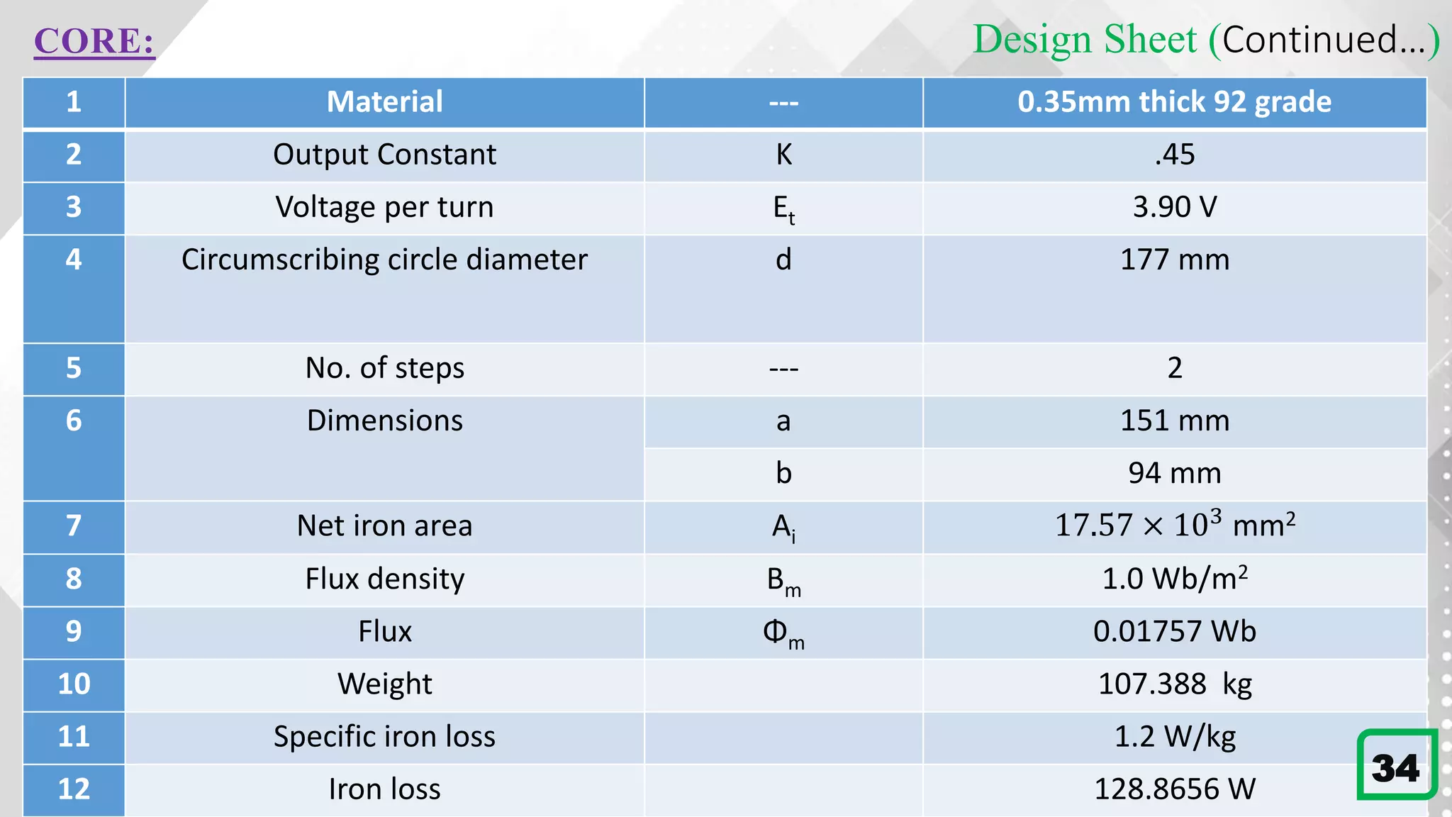
The value of k is taken from the table, [7.2 in A course in Electrical Machine Design. AK. Sawhney]
K=0.45 for 3-phase core type distribution transformer.
Voltage per turn Et =K 𝑄 =0.45 75 =3.90 V Therefore,
Flux in the core, Φm =
𝐸𝑡
4.44×𝑓
=
3.90
4.44×50
= 0.01757 Wb
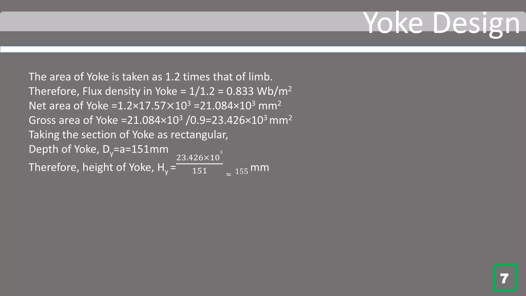
Hot rolled silicon steel grade 92 is used. The value of flux density Bm is assumed as 1.0 Wb/m2.
Net iron Area Ai=
0.01757
1.0
= 0.01757 = 17.57×103 mm2
Using a cruciform core, Ai =0.56d2
Diameter of circumscribing circle, d =
17.57×10³
0
.
56
=177.13 mm≈177 mm
Reference widths of laminations:
a=0.85d=0.85×177 =150.45 mm
b=0.53d=0.53×177=93.81 mm
The nearest standard dimensions are: a =151 mm and b =94 mm
3
Type K
Single phase shell type 1-1.2
Single phase core type 0.75-0.85
Three phase shell type 1.3
Three phase core
type(distribution)
0.45
Single phase shell
type(power)
0.6 to 0.7
Area percentage
of circumscribing
circle
Square Cruciform Three
Stepped
Four
step
Net core area,Ai 0.45 0.56 0.6 0.62](https://image.slidesharecdn.com/transformerdesign-200604230524/75/Project-on-Transformer-Design-Electrical-Machine-Design-5-2048.jpg)
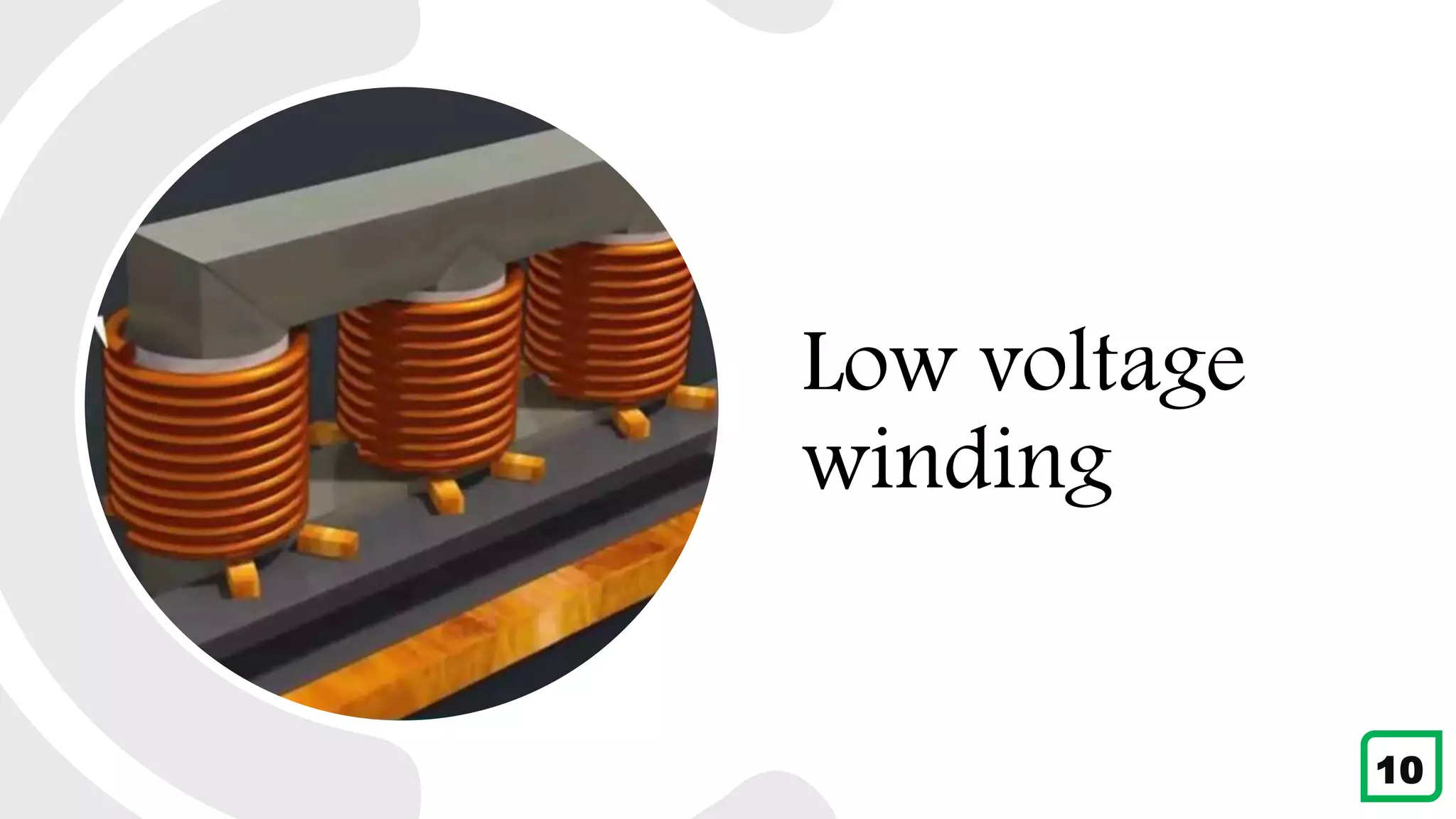
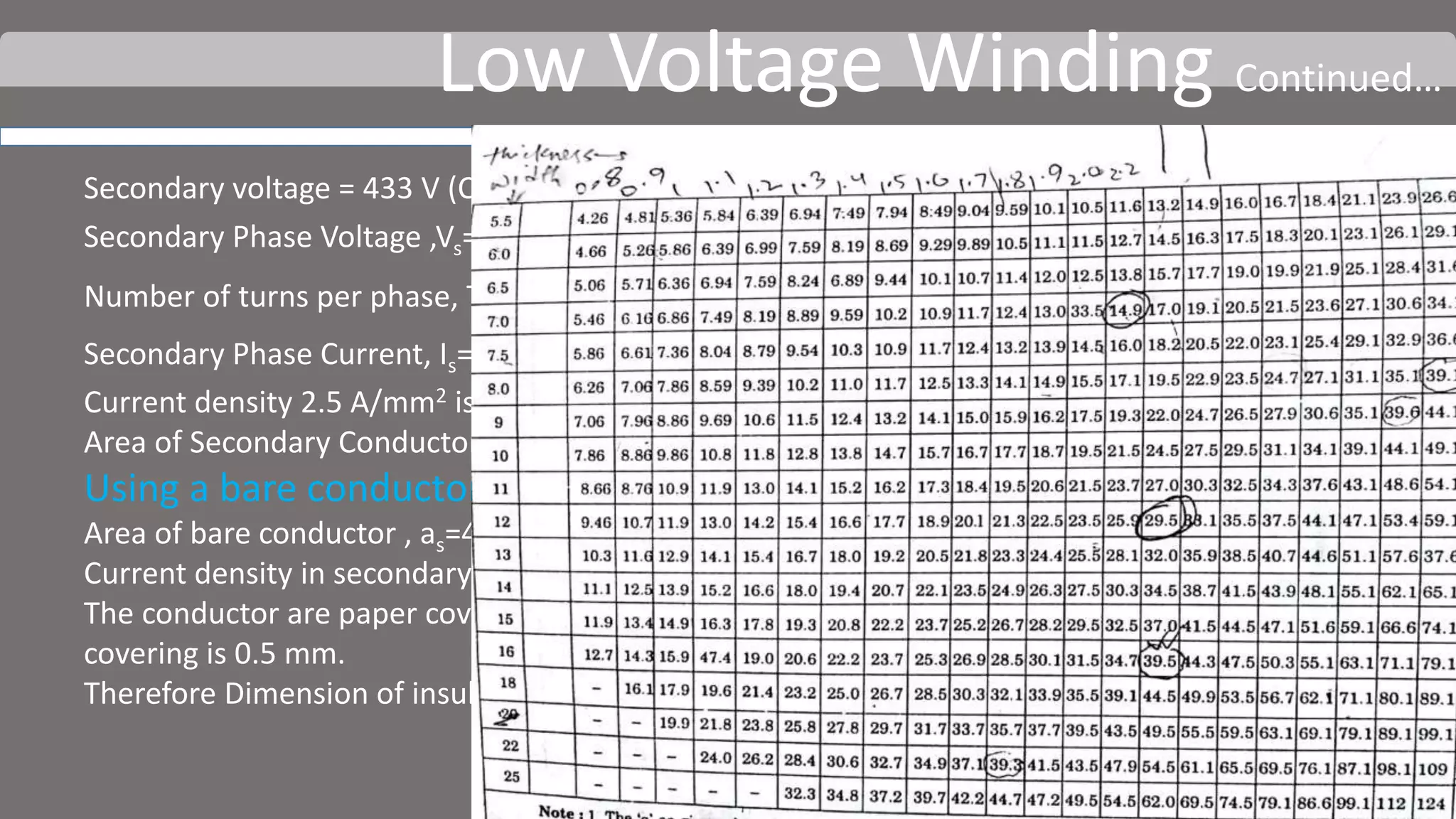
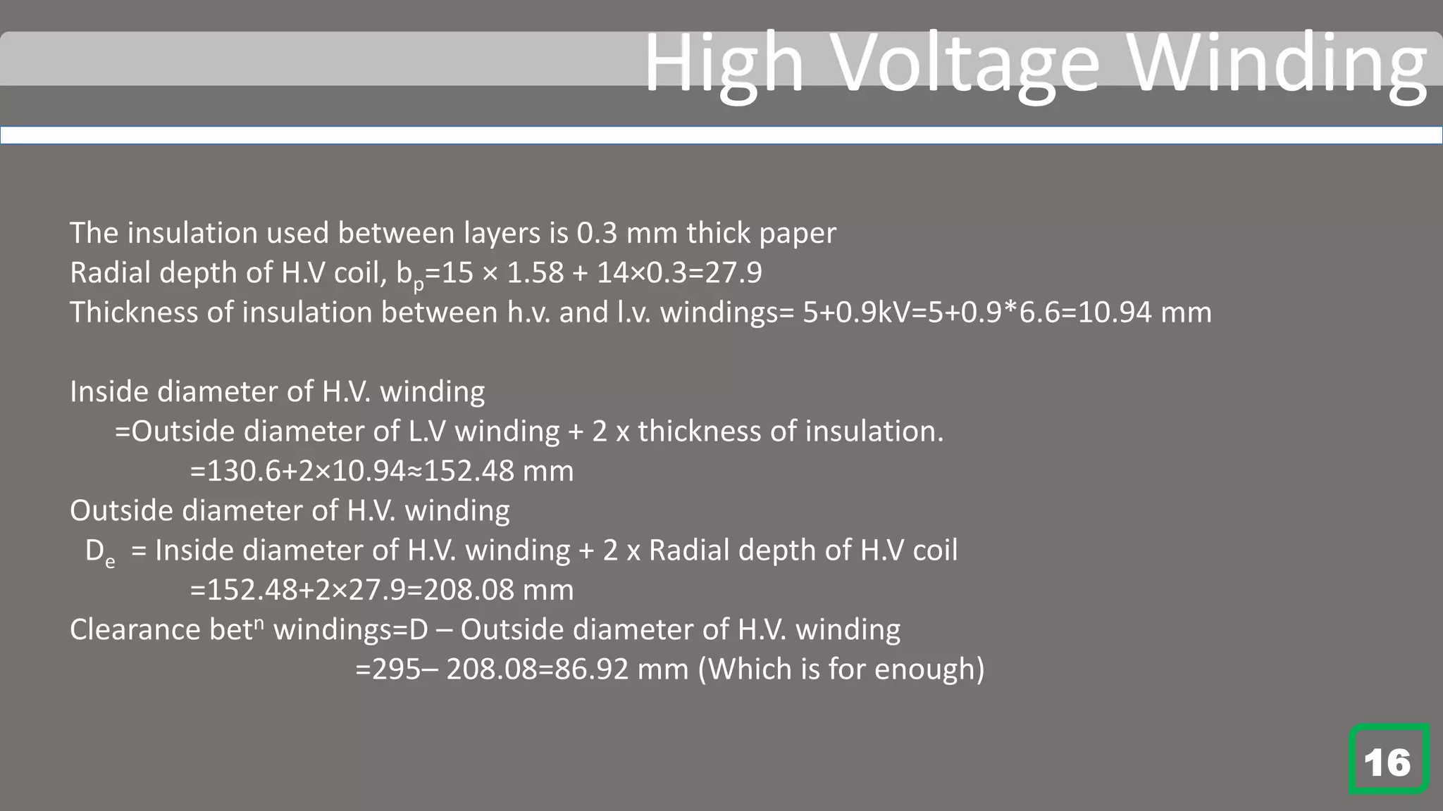
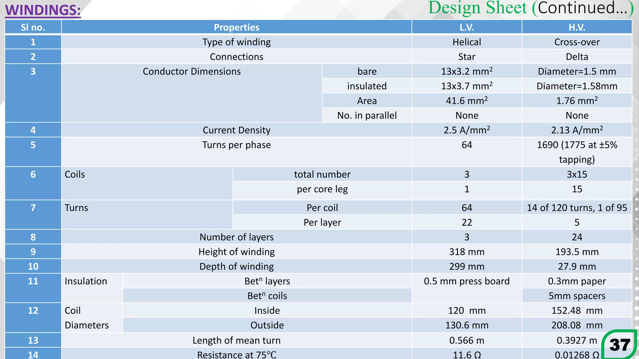
![Low Voltage Winding
Using 3 layers for the winding.
Helical winding is used. Therefore, space has to be provided (
𝑇𝑠
3
+ 1)=(
64
3
+ 1) =22.3= 23 (approx)
turns along the axial depth.
Axial depth of L.V winding, Lcs =23×13=299 mm
The Height of window is 486 mm. This leaves a clearance of (318-299)/2=9.5 mm of each side of the
windings. [Which fulfill the minimum requirement 6 mm]
Radial depth of low voltage winding,
bs=no. of layers x radial depth of conductor + insulator betn layers
=3×3.2+2×0.5 = 10.6 mm
Diameter of circumscribing circle, d =177 mm
Using pressboard wraps 1.5 mm thick as insulation between l.v. winding and core.
Inside diameter of l.v. winding=117+1.5×2=120 mm
Outside diameter of l.v. winding= 120+10.6 =130.6 mm 12](https://image.slidesharecdn.com/transformerdesign-200604230524/75/Project-on-Transformer-Design-Electrical-Machine-Design-14-2048.jpg)

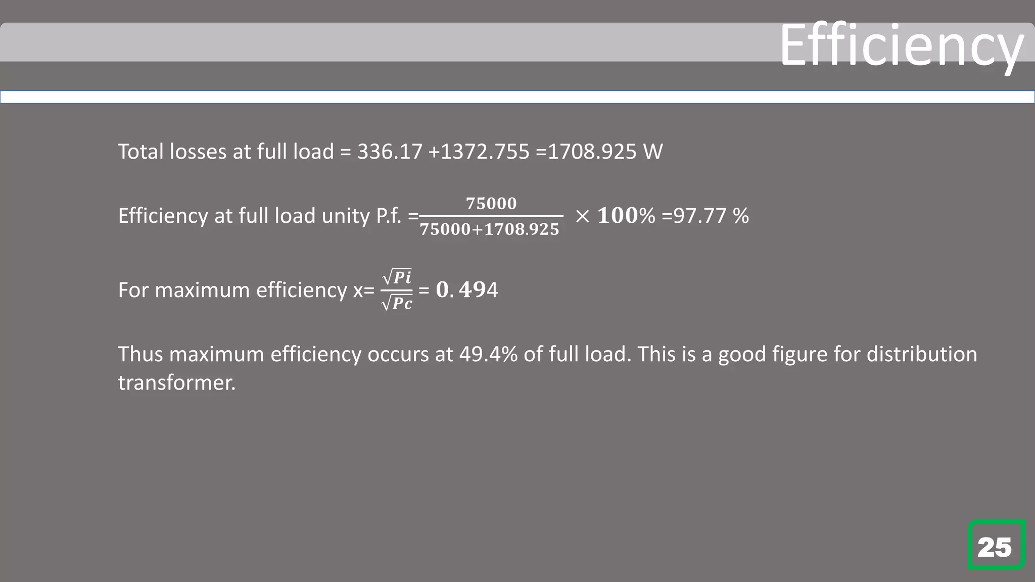

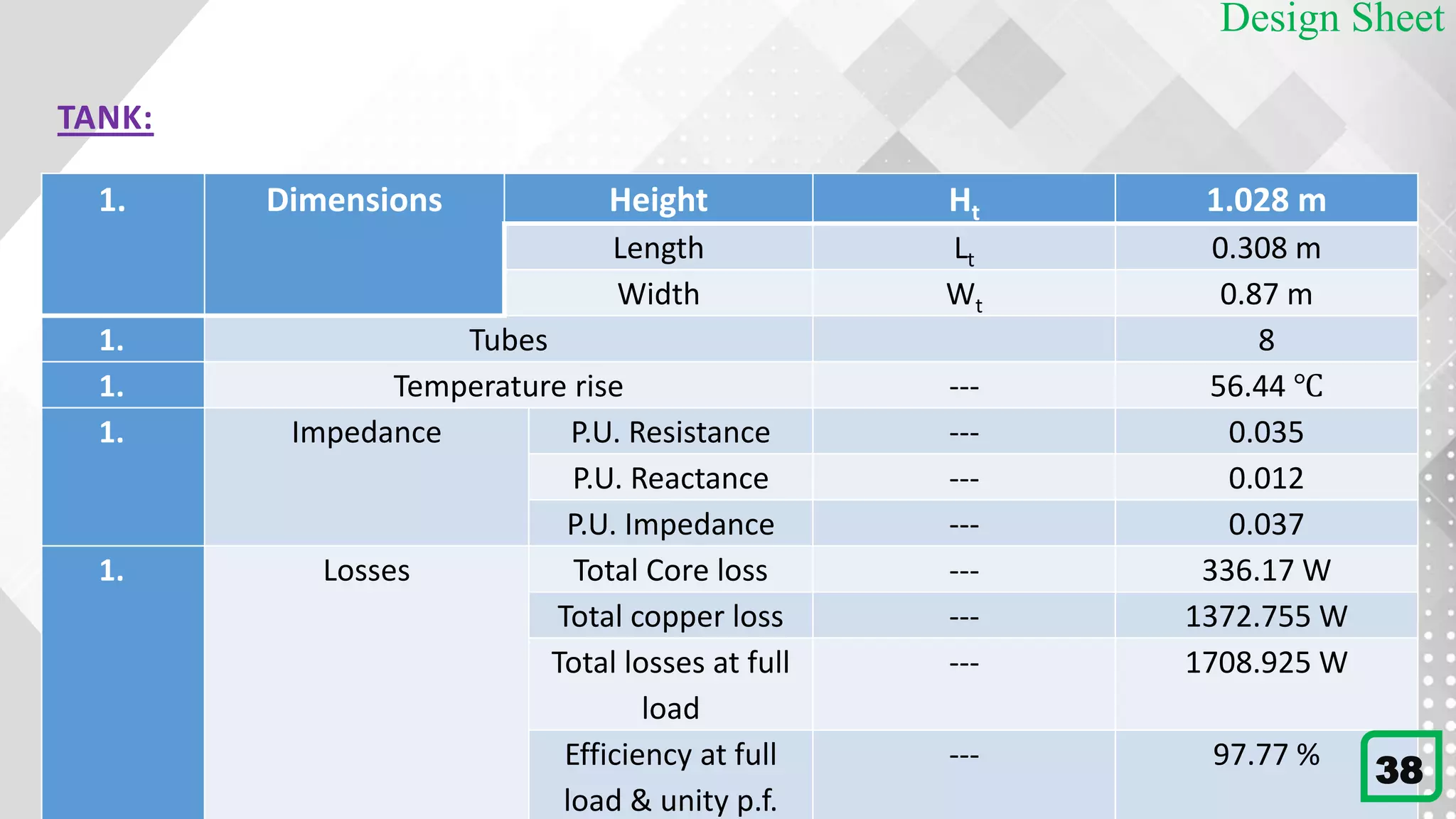


This document details the design process for a 65 kVA, 11 kV/400 V, 50 Hz, three-phase core type transformer. It outlines objectives, design requirements, calculations for dimensions, winding configurations, losses, and efficiency metrics, using specific formulas and materials such as silicon steel for the core. The final analysis indicates that additional cooling methods are necessary to maintain acceptable temperature levels during operation.