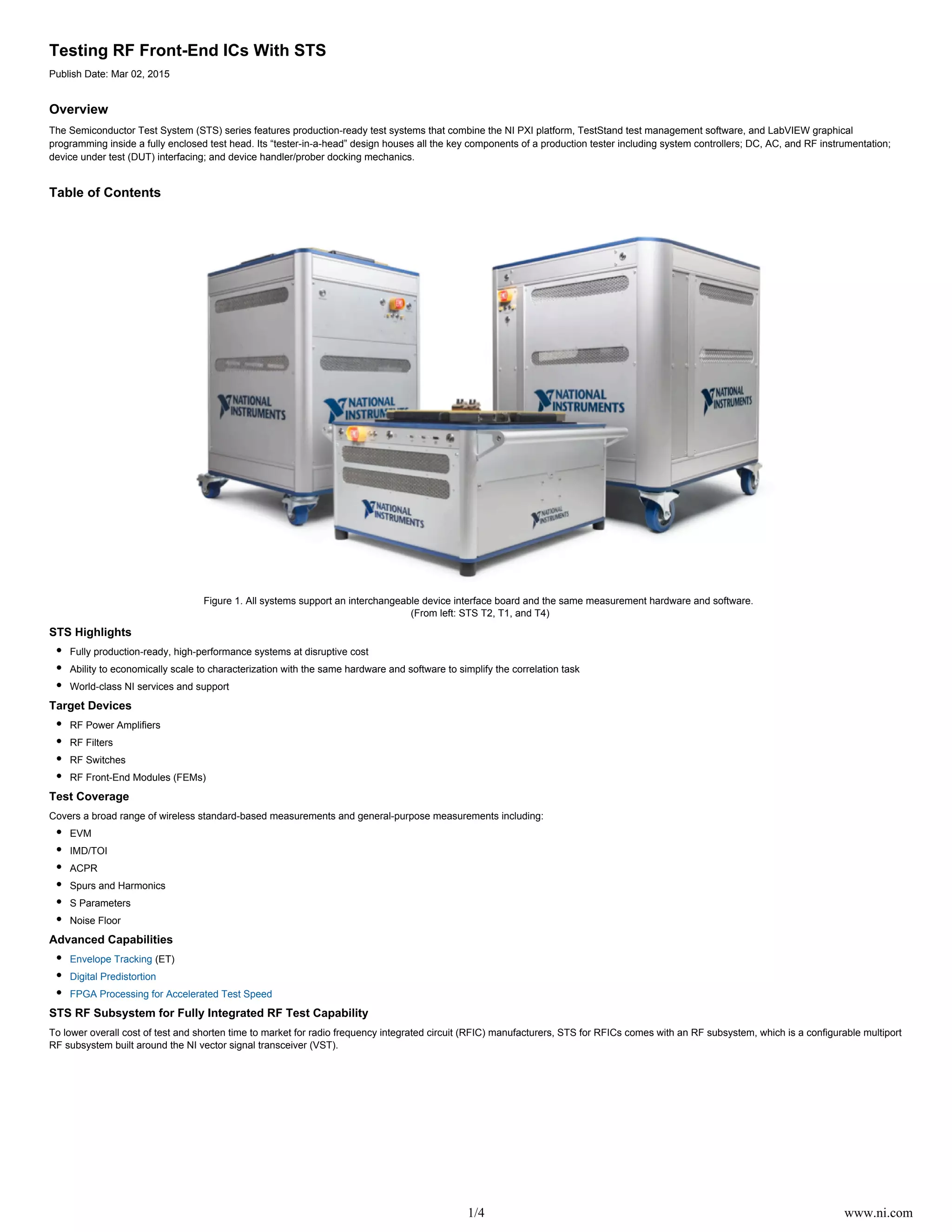
1/4 www.ni.com
Testing RF Front-End ICs With STS
Publish Date: Mar 02, 2015
Overview
The Semiconductor Test System (STS) series features production-ready test systems that combine the NI PXI platform, TestStand test management software, and LabVIEW graphical
programming inside a fully enclosed test head. Its “tester-in-a-head” design houses all the key components of a production tester including system controllers; DC, AC, and RF instrumentation;
device under test (DUT) interfacing; and device handler/prober docking mechanics.
Table of Contents
Figure 1. All systems support an interchangeable device interface board and the same measurement hardware and software.
(From left: STS T2, T1, and T4)
STS Highlights
Fully production-ready, high-performance systems at disruptive cost
Ability to economically scale to characterization with the same hardware and software to simplify the correlation task
World-class NI services and support
Target Devices
RF Power Amplifiers
RF Filters
RF Switches
RF Front-End Modules (FEMs)
Test Coverage
Covers a broad range of wireless standard-based measurements and general-purpose measurements including:
EVM
IMD/TOI
ACPR
Spurs and Harmonics
S Parameters
Noise Floor
Advanced Capabilities
Envelope Tracking (ET)
Digital Predistortion
FPGA Processing for Accelerated Test Speed
STS RF Subsystem for Fully Integrated RF Test Capability
To lower overall cost of test and shorten time to market for radio frequency integrated circuit (RFIC) manufacturers, STS for RFICs comes with an RF subsystem, which is a configurable multiport
RF subsystem built around the NI vector signal transceiver (VST).
2/4 www.ni.com
Figure 2. STS T2 With Multiport RF Subsystem
The VST combines a vector signal generator and vector signal analyzer with FPGA-based real-time signal processing and control. Key VST features include:
Fast measurement speed and small form factor of a production test box
Flexibility and high-performance of R&D-grade box instruments
User-programmable FPGA
200 MHz instantaneous bandwidth
The rest of the RF subsystem includes:
RF Port Control Module
RF Quad Port Module
RF Blind Mate Interface
Automatic Multiport RF Calibration Module
Overall, STS for RFICs offers a fully integrated RF test capability to meet the stringent measurement and scalability requirements for RF production test.
STS Software
At the core of STS is TestStand ready-to-run test management software, which is designed to help engineers quickly develop, debug, and deploy test programs. Key features include:
Test Sequence Editor with multisite support
Operator interface
DUT-centric test programming
STDF reports
Handler/prober integration
3/4 www.ni.com
Figure 3. The STS operator interface provides a single powerful interface to select, run, and view all key data.
STS Interfacing and System Calibration
Figure 4. The spring probe interface includes Coax, DC, and RF (blind mate). STS comes with system-level calibration to spring probe interfaces (coax and DC) and RF blindmates.
Figure 5. The automatic RF Multiport Calibration Module provides efficient in-situ system-level calibration to minimize system downtime. To ensure accurate measurements at DUT, the RF
subsystem comes with the capability to de-embed RF paths on the device interface board.
4/4 www.ni.com
Typical System Resources for RF Front-End ICs With an STS T2
RF Subsystem 1 with up to 48 RF portsVST
2 s with up to 24 RF portsVST
4 s with up to 12 RF portsVST
DC Source Measure (SMUs) Precision System SMU (up to 24 channels per system)
4-channel SMU (up to 96 channels per system)
Digital Instruments Up to 200 MHz with PPMU (up to 240 channels)
Optional Instruments Digitizers/Oscilloscopes
Arbitrary Waveform Generators
Dynamic Signal Acquisition Instruments
Power Supplies
High-Speed Serial Interfaces
Multimeters are available for configuration inside STS
Figure 6. Example Configuration of an STS T2 With One VST With 12 RF Ports
For more information on configuring an STS or to speak with a semiconductor expert, email .sts@ni.com

Testing RF Front-End ICs With STS

  • 1.
    1/4 www.ni.com Testing RFFront-End ICs With STS Publish Date: Mar 02, 2015 Overview The Semiconductor Test System (STS) series features production-ready test systems that combine the NI PXI platform, TestStand test management software, and LabVIEW graphical programming inside a fully enclosed test head. Its “tester-in-a-head” design houses all the key components of a production tester including system controllers; DC, AC, and RF instrumentation; device under test (DUT) interfacing; and device handler/prober docking mechanics. Table of Contents Figure 1. All systems support an interchangeable device interface board and the same measurement hardware and software. (From left: STS T2, T1, and T4) STS Highlights Fully production-ready, high-performance systems at disruptive cost Ability to economically scale to characterization with the same hardware and software to simplify the correlation task World-class NI services and support Target Devices RF Power Amplifiers RF Filters RF Switches RF Front-End Modules (FEMs) Test Coverage Covers a broad range of wireless standard-based measurements and general-purpose measurements including: EVM IMD/TOI ACPR Spurs and Harmonics S Parameters Noise Floor Advanced Capabilities Envelope Tracking (ET) Digital Predistortion FPGA Processing for Accelerated Test Speed STS RF Subsystem for Fully Integrated RF Test Capability To lower overall cost of test and shorten time to market for radio frequency integrated circuit (RFIC) manufacturers, STS for RFICs comes with an RF subsystem, which is a configurable multiport RF subsystem built around the NI vector signal transceiver (VST).
  • 2.
    2/4 www.ni.com Figure 2.STS T2 With Multiport RF Subsystem The VST combines a vector signal generator and vector signal analyzer with FPGA-based real-time signal processing and control. Key VST features include: Fast measurement speed and small form factor of a production test box Flexibility and high-performance of R&D-grade box instruments User-programmable FPGA 200 MHz instantaneous bandwidth The rest of the RF subsystem includes: RF Port Control Module RF Quad Port Module RF Blind Mate Interface Automatic Multiport RF Calibration Module Overall, STS for RFICs offers a fully integrated RF test capability to meet the stringent measurement and scalability requirements for RF production test. STS Software At the core of STS is TestStand ready-to-run test management software, which is designed to help engineers quickly develop, debug, and deploy test programs. Key features include: Test Sequence Editor with multisite support Operator interface DUT-centric test programming STDF reports Handler/prober integration
  • 3.
    3/4 www.ni.com Figure 3.The STS operator interface provides a single powerful interface to select, run, and view all key data. STS Interfacing and System Calibration Figure 4. The spring probe interface includes Coax, DC, and RF (blind mate). STS comes with system-level calibration to spring probe interfaces (coax and DC) and RF blindmates. Figure 5. The automatic RF Multiport Calibration Module provides efficient in-situ system-level calibration to minimize system downtime. To ensure accurate measurements at DUT, the RF subsystem comes with the capability to de-embed RF paths on the device interface board.
  • 4.
    4/4 www.ni.com Typical SystemResources for RF Front-End ICs With an STS T2 RF Subsystem 1 with up to 48 RF portsVST 2 s with up to 24 RF portsVST 4 s with up to 12 RF portsVST DC Source Measure (SMUs) Precision System SMU (up to 24 channels per system) 4-channel SMU (up to 96 channels per system) Digital Instruments Up to 200 MHz with PPMU (up to 240 channels) Optional Instruments Digitizers/Oscilloscopes Arbitrary Waveform Generators Dynamic Signal Acquisition Instruments Power Supplies High-Speed Serial Interfaces Multimeters are available for configuration inside STS Figure 6. Example Configuration of an STS T2 With One VST With 12 RF Ports For more information on configuring an STS or to speak with a semiconductor expert, email .sts@ni.com