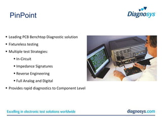
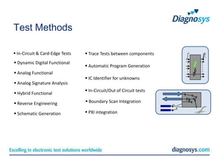
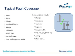
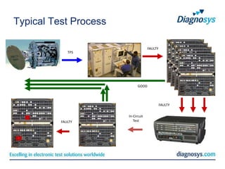
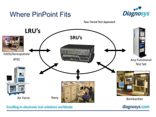
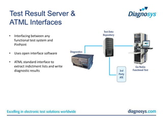
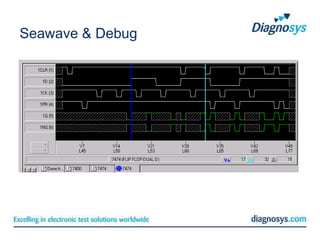
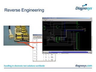
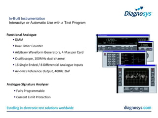
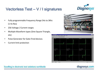
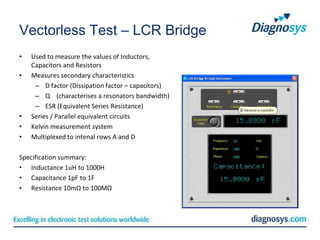
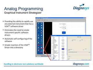
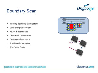
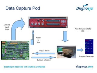
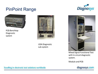
PinPoint System
Technical Presentation
PinPoint System
PinPoint

 Leading PCB Benchtop Diagnostic solution
 Fixtureless testing
 Multiple test Strategies:
      In-Circuit
      Impedance Signatures
      Reverse Engineering
      Full Analog and Digital
 Provides rapid diagnostics to Component Level
Test Methods

 In-Circuit & Card-Edge Tests    Trace Tests between components
 Dynamic Digital Functional
                                  Automatic Program Generation
 Analog Functional
                                  IC Identifier for unknowns
 Analog Signature Analysis
                                  In-Circuit/Out of Circuit tests
 Hybrid Functional

 Reverse Engineering             Boundary Scan Integration

 Schematic Generation            PXI integration
Typical Fault Coverage
 Opens                         Component tests include:

 Shorts                             Memory

 Voltage                            Processors

 Functional failures                Counters

 Leakage                            Registers

 Cold Solder                        Programmable

 Broken Trace                       DTL, TTL, ECL, CMOS Etc

 Corrupt firmware                   Analog

 Incorrect Component values         Many More….
Typical Test Process

                                    FAULTY
             TPS


                             GOOD


                                             FAULTY


                       In-Circuit
          FAULTY          Test
Where PinPoint Fits
                                    Two-Tiered Test Approach


             LRU’s
                            SRU’s


EADS/Aerospatiale
      ATEC                                                       Any Functional
                                                                    Test Set


        Air Force    Navy                                      Bombardier
Test Result Server &
ATML Interfaces
•   Interfacing between any
    functional test system and
    PinPoint

•   Uses open interface software

•   ATML standard interface to
    extract indictment lists and write
    diagnostic results
US Air Force AWACS
Saving Programming Time

Typical TPS programming time.

 GO/NOGO                        DIAGNOSTICS
 12 Weeks                         36 Weeks


Diagnostics programming with the PinPoint


  GO/NOGO              DIAGNOSTICS
  12 Weeks                2 weeks
Automatic Fixtureless Test Methods
Providing Test, Consistency and Result Data


 Analog Functional                                  Dynamic Digital

 Network Signatures                                 Boundary Scan

                                              TMS
                                              TCK
                                              TDI                       TDO
Device Test Interface
• Robust custom Interfaces
• Fatigue Life of over 1,000,000 cycles
• Ergonomic Handles for Even Weight Dist.
• Repairable should a pin fail
• Down to 0.4mm pin-pitch
DTI Package Range


          SSOP      TSOP   TSSOP
          TSOP1   QVSOP    QFP
          PQFP      TQFP   PGA
           DIP      ZIP    PLCC
Programming

         Simple In-Circuit Graphical Environments


           TestVue™ - Software
TestFlow
Seawave & Debug
Reverse Engineering
In-Built Instrumentation
 Interactive or Automatic Use with a Test Program


Functional Analogue
    DMM
    Dual Timer Counter
    Arbitrary Waveform Generators, 4 Max per Card
    Oscilloscope, 100MHz dual channel
    16 Single Ended / 8 Differential Analogue Inputs
    Avionics Reference Output, 400Hz 26V


Analogue Signature Analyser
     Fully Programmable
     Current Limit Protection
In-Built Instrumentation

   4 ½ Digit Digital Multi Meter
   100Mhz Dual Channel Oscilloscope
   Dual Channel Frequency / Timer Counter
   Arbitrary Waveform Generator 4 max per card
   16 Single Ended / 8 Differential Analog Inputs
Vectorless Test – V / I signatures

•    Fully programmable Frequency Range 5Hz to 3Khz
     (1 Hz Res)
•    256 Voltage / Current ranges
•    Multiple Waveform types (Sine Square Triangle,
     etc)
•    Pulse Generator for Gate-Fired devices
•    Current limit protection
Vectorless Test – Shorts Locator

•   Interactive tool to determine the exact point
    at which a short circuit has occurred
•   Intuitive User Interface
•   Audible and graphical display to guide the
    user
•   Specification summary:
      – 500mV max o/c voltage
      – 1A max s/c current
      – 3 sense ranges (x1, x10, x100)
      – User selectable audio frequency output
Vectorless Test – LCR Bridge
•   Used to measure the values of Inductors,
    Capacitors and Resistors
•   Measures secondary characteristics
     – D factor (Dissipation factor – capacitors)
     – Q (characterises a resonators bandwidth)
     – ESR (Equivalent Series Resistance)
•   Series / Parallel equivalent circuits
•   Kelvin measurement system
•   Multiplexed to intenal rows A and D

Specification summary:
• Inductance 1uH to 1000H
• Capacitance 1pF to 1F
• Resistance 10mΩ to 100MΩ
Vectorless Test – PTU
Parametric Test Unit
• Four independent channels dedicated to precision DC voltage and current sources
• Provide functional testing of discrete components in and out of circuit:
• Programmable voltage and current on each channel
• Each channel can sink or source current or voltage
• Semiconductor junction forward voltage
• Output drive levels of devices or circuits
• Tri-state leakage current
• hFE of transistors

Specification summary
• + / - 10V
• + / - 20mA
• 2.5mV resolution
• 5uA resolution
Analog Programming
 Graphical Instrument Strategizer


 Providing the ability to rapidly use
  any external instrument that has a
  VISATM software driver
 Eliminates the need to create
  instrument specific software
  drivers
 Automatic self-configuring of the
  software
 Simple insertion of the VISATM
  Driver into a directory
Analog Programming
  ‘C’ Function Editor


‘C’ Function Editor
 Providing the power of the ‘C’ programming language
 Easily included in the standard TestFlow structure using the drag-and-drop icon provided
Boundary Scan
                                   TMS
                                   TCK
                                   TDI   TDO
   Leading Boundary Scan System
   JTAG Compliant System
   Quick & easy to Use
   Tests BGA Components
   Tests complete boards
   Provides device status
   Pin Points Faults
Data Capture Pod


Capture
 Input
  Data                             Pass stimulus data to
                                            PPII


               Reset
                or
               Sync


                  Inputs driven

                                        Program Generated
               Outputs collected
Bed of Nails Option

Provides:
Interface for fixtures (VP G12)
Housing for multiplexer cards
Automatic testing of devices


Includes:
Bed of Nails Software
PinPoint Range


PCB Benchtop
Diagnostic
system


                 UDA Diagnostic
                 sub-system

                                  Mixed Signal Functional Test
                                  with In-circuit diagnostic
                                  system.
                                  Module and PCB
Diagnostic Sub-System


                                                          19” rack   Diagnostic sub-
                                                                     system

                                                 10U


 Integration with third-party functional test sets to
  provide excellent and proven PCB component level
  diagnostic capability
 Rugged versions for deployable applications
 Scaleable diagnostic capabilities through an industry
  standard 19” rack mounting
 Runs under the proven TestVUETM suite
PinPoint UDA
                 PCB Diagnostics
Module Test      To component and network
 Digital          level
 Analog          Guided Probe
 Mixed Signal        Dynamic functional
                      Analog Signatures
                  Component Functionality
                  Values of Passive devices
Keeping your electronics working

Pin pointpresentation

  • 1.
  • 2.
  • 3.
    PinPoint  Leading PCBBenchtop Diagnostic solution  Fixtureless testing  Multiple test Strategies:  In-Circuit  Impedance Signatures  Reverse Engineering  Full Analog and Digital  Provides rapid diagnostics to Component Level
  • 4.
    Test Methods  In-Circuit& Card-Edge Tests  Trace Tests between components  Dynamic Digital Functional  Automatic Program Generation  Analog Functional  IC Identifier for unknowns  Analog Signature Analysis  In-Circuit/Out of Circuit tests  Hybrid Functional  Reverse Engineering  Boundary Scan Integration  Schematic Generation  PXI integration
  • 5.
    Typical Fault Coverage Opens  Component tests include:  Shorts  Memory  Voltage  Processors  Functional failures  Counters  Leakage  Registers  Cold Solder  Programmable  Broken Trace  DTL, TTL, ECL, CMOS Etc  Corrupt firmware  Analog  Incorrect Component values  Many More….
  • 6.
    Typical Test Process FAULTY TPS GOOD FAULTY In-Circuit FAULTY Test
  • 7.
    Where PinPoint Fits Two-Tiered Test Approach LRU’s SRU’s EADS/Aerospatiale ATEC Any Functional Test Set Air Force Navy Bombardier
  • 8.
    Test Result Server& ATML Interfaces • Interfacing between any functional test system and PinPoint • Uses open interface software • ATML standard interface to extract indictment lists and write diagnostic results
  • 9.
    US Air ForceAWACS Saving Programming Time Typical TPS programming time. GO/NOGO DIAGNOSTICS 12 Weeks 36 Weeks Diagnostics programming with the PinPoint GO/NOGO DIAGNOSTICS 12 Weeks 2 weeks
  • 10.
    Automatic Fixtureless TestMethods Providing Test, Consistency and Result Data  Analog Functional  Dynamic Digital  Network Signatures  Boundary Scan TMS TCK TDI TDO
  • 11.
    Device Test Interface •Robust custom Interfaces • Fatigue Life of over 1,000,000 cycles • Ergonomic Handles for Even Weight Dist. • Repairable should a pin fail • Down to 0.4mm pin-pitch
  • 12.
    DTI Package Range SSOP TSOP TSSOP TSOP1 QVSOP QFP PQFP TQFP PGA DIP ZIP PLCC
  • 13.
    Programming Simple In-Circuit Graphical Environments TestVue™ - Software
  • 14.
  • 15.
  • 16.
  • 17.
    In-Built Instrumentation Interactiveor Automatic Use with a Test Program Functional Analogue  DMM  Dual Timer Counter  Arbitrary Waveform Generators, 4 Max per Card  Oscilloscope, 100MHz dual channel  16 Single Ended / 8 Differential Analogue Inputs  Avionics Reference Output, 400Hz 26V Analogue Signature Analyser  Fully Programmable  Current Limit Protection
  • 18.
    In-Built Instrumentation  4 ½ Digit Digital Multi Meter  100Mhz Dual Channel Oscilloscope  Dual Channel Frequency / Timer Counter  Arbitrary Waveform Generator 4 max per card  16 Single Ended / 8 Differential Analog Inputs
  • 19.
    Vectorless Test –V / I signatures • Fully programmable Frequency Range 5Hz to 3Khz (1 Hz Res) • 256 Voltage / Current ranges • Multiple Waveform types (Sine Square Triangle, etc) • Pulse Generator for Gate-Fired devices • Current limit protection
  • 20.
    Vectorless Test –Shorts Locator • Interactive tool to determine the exact point at which a short circuit has occurred • Intuitive User Interface • Audible and graphical display to guide the user • Specification summary: – 500mV max o/c voltage – 1A max s/c current – 3 sense ranges (x1, x10, x100) – User selectable audio frequency output
  • 21.
    Vectorless Test –LCR Bridge • Used to measure the values of Inductors, Capacitors and Resistors • Measures secondary characteristics – D factor (Dissipation factor – capacitors) – Q (characterises a resonators bandwidth) – ESR (Equivalent Series Resistance) • Series / Parallel equivalent circuits • Kelvin measurement system • Multiplexed to intenal rows A and D Specification summary: • Inductance 1uH to 1000H • Capacitance 1pF to 1F • Resistance 10mΩ to 100MΩ
  • 22.
    Vectorless Test –PTU Parametric Test Unit • Four independent channels dedicated to precision DC voltage and current sources • Provide functional testing of discrete components in and out of circuit: • Programmable voltage and current on each channel • Each channel can sink or source current or voltage • Semiconductor junction forward voltage • Output drive levels of devices or circuits • Tri-state leakage current • hFE of transistors Specification summary • + / - 10V • + / - 20mA • 2.5mV resolution • 5uA resolution
  • 23.
    Analog Programming GraphicalInstrument Strategizer  Providing the ability to rapidly use any external instrument that has a VISATM software driver  Eliminates the need to create instrument specific software drivers  Automatic self-configuring of the software  Simple insertion of the VISATM Driver into a directory
  • 24.
    Analog Programming ‘C’ Function Editor ‘C’ Function Editor  Providing the power of the ‘C’ programming language  Easily included in the standard TestFlow structure using the drag-and-drop icon provided
  • 25.
    Boundary Scan TMS TCK TDI TDO  Leading Boundary Scan System  JTAG Compliant System  Quick & easy to Use  Tests BGA Components  Tests complete boards  Provides device status  Pin Points Faults
  • 26.
    Data Capture Pod Capture Input Data Pass stimulus data to PPII Reset or Sync Inputs driven Program Generated Outputs collected
  • 27.
    Bed of NailsOption Provides: Interface for fixtures (VP G12) Housing for multiplexer cards Automatic testing of devices Includes: Bed of Nails Software
  • 28.
    PinPoint Range PCB Benchtop Diagnostic system UDA Diagnostic sub-system Mixed Signal Functional Test with In-circuit diagnostic system. Module and PCB
  • 29.
    Diagnostic Sub-System 19” rack Diagnostic sub- system 10U  Integration with third-party functional test sets to provide excellent and proven PCB component level diagnostic capability  Rugged versions for deployable applications  Scaleable diagnostic capabilities through an industry standard 19” rack mounting  Runs under the proven TestVUETM suite
  • 30.
    PinPoint UDA PCB Diagnostics Module Test To component and network  Digital level  Analog  Guided Probe  Mixed Signal  Dynamic functional  Analog Signatures  Component Functionality  Values of Passive devices
  • 31.