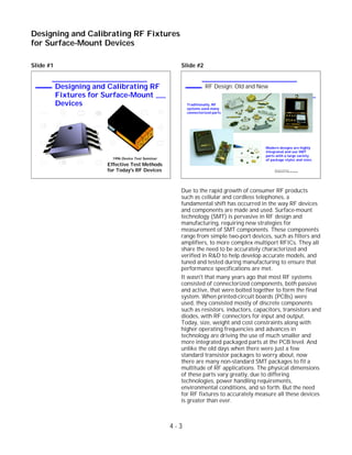
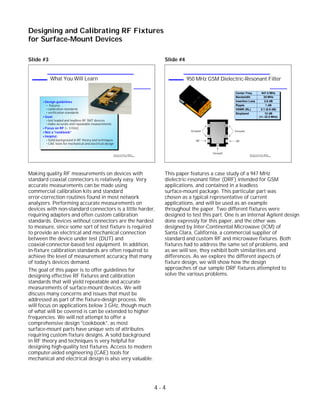
Agilent
Designing and Calibrating RF
Fixtures for Surface-Mount
Devices
1996 Device Test Seminar
Effective Test Methods
for Today's RF Devices
Abstract
Many devices in today's communications systems are
contained in leaded or leadless surface-mount packages,
without coaxial connectors. Measuring these devices
requires a test fixture in order to interface to coaxial-based
test equipment. This paper covers techniques to design
high-quality RF fixtures and the calibration standards
needed for accurate measurements. These techniques are
useful for both leaded and leadless components, from
simple two-port devices such as filters, up to more complex
multiport RFICs. Calibration alternatives will be discussed
and methods will be presented to verify the raw and
corrected performance of the fixtures. Included is a case
study documenting the fixture-design process for a 947
MHz leadless dielectric-resonant filter.
Slide #1 Slide #2
Due to the rapid growth of consumer RF products
such as cellular and cordless telephones, a
fundamental shift has occurred in the way RF devices
and components are made and used. Surface-mount
technology (SMT) is pervasive in RF design and
manufacturing, requiring new strategies for
measurement of SMT components. These components
range from simple two-port devices, such as filters and
amplifiers, to more complex multiport RFICs. They all
share the need to be accurately characterized and
verified in R&D to help develop accurate models, and
tuned and tested during manufacturing to ensure that
performance specifications are met.
It wasn't that many years ago that most RF systems
consisted of connectorized components, both passive
and active, that were bolted together to form the final
system. When printed-circuit boards (PCBs) were
used, they consisted mostly of discrete components
such as resistors, inductors, capacitors, transistors and
diodes, with RF connectors for input and output.
Today, size, weight and cost constraints along with
higher operating frequencies and advances in
technology are driving the use of much smaller and
more integrated packaged parts at the PCB level. And
unlike the old days when there were just a few
standard transistor packages to worry about, now
there are many non-standard SMT packages to fit a
multitude of RF applications. The physical dimensions
of these parts vary greatly, due to differing
technologies, power handling requirements,
environmental conditions, and so forth. But the need
for RF fixtures to accurately measure all these devices
is greater than ever.
4 - 3
Designing and Calibrating RF Fixtures
for Surface-Mount Devices
Designing and Calibrating RF
Fixtures for Surface-Mount
Devices
1996 Device Test Seminar
Effective Test Methods
for Today's RF Devices 1996 Device Test Seminar:
Test Methods for Today's RF Devices
RF Design: Old and New
Traditionally, RF
systems used many
connectorized parts
Modern designs are highly
integrated and use SMT
parts with a large variety
of package styles and sizes
Slide #3
Making quality RF measurements on devices with
standard coaxial connectors is relatively easy. Very
accurate measurements can be made using
commercial calibration kits and standard
error-correction routines found in most network
analyzers. Performing accurate measurements on
devices with non-standard connectors is a little harder,
requiring adapters and often custom calibration
standards. Devices without connectors are the hardest
to measure, since some sort of test fixture is required
to provide an electrical and mechanical connection
between the device under test (DUT) and
coaxial-connector-based test equipment. In addition,
in-fixture calibration standards are often required to
achieve the level of measurement accuracy that many
of today's devices demand.
The goal of this paper is to offer guidelines for
designing effective RF fixtures and calibration
standards that will yield repeatable and accurate
measurements of surface-mount devices. We will
discuss many concerns and issues that must be
addressed as part of the fixture-design process. We
will focus on applications below 3 GHz, though much
of what will be covered is can be extended to higher
frequencies. We will not attempt to offer a
comprehensive design "cookbook", as most
surface-mount parts have unique sets of attributes
requiring custom fixture designs. A solid background
in RF theory and techniques is very helpful for
designing high-quality test fixtures. Access to modern
computer-aided engineering (CAE) tools for
mechanical and electrical design is also very valuable.
Slide #4
This paper features a case study of a 947 MHz
dielectric-resonant filter (DRF) intended for GSM
applications, and contained in a leadless
surface-mount package. This particular part was
chosen as a typical representative of current
applications, and will be used as an example
throughout the paper. Two different fixtures were
designed to test this part. One is an internal Agilent design
done expressly for this paper, and the other was
designed by Inter-Continental Microwave (ICM) of
Santa Clara, California, a commercial supplier of
standard and custom RF and microwave fixtures. Both
fixtures had to address the same set of problems, and
as we will see, they exhibit both similarities and
differences. As we explore the different aspects of
fixture design, we will show how the design
approaches of our sample DRF fixtures attempted to
solve the various problems.
4 - 4
Designing and Calibrating RF Fixtures
for Surface-Mount Devices
1996 Device Test Seminar: Effective
Test Methods for Today's RF Devices
950 MHz GSM Dielectric-Resonant Filter
947C
D
-67A
Center Freq. 947.5 MHz
Bandwidth 25 MHz
Insertion Loss 2.6 dB
Ripple 1 dB
VSWR (RL) 2:1 (9.5 dB)
Stopband 12 dB
(+/- 32.5 MHz)
Ground
RF RF
Ground
Ground1996 Device Test Seminar: Effective
Test Methods for Today's RF Devices
What You Will Learn
Design guidelines
fixtures
calibration standards
verification standards
Goal:
test leaded and leadless RF SMT devices
make accurate and repeatable measurements
Focus on RF (< 3 GHz)
Not a "cookbook"
Helpful:
Solid background in RF theory and techniques
CAE tools for mechanical and electrical design
Slide #5
We will start out discussing fixturing basics, including
the goal of fixtures and what separates an ideal fixture
from one that can be achieved in the real world. We
will cover both electrical and mechanical challenges of
designing fixtures, as well as other considerations that
must be taken into account before finally deciding on
the optimum design approach.
Next, we will cover various aspects of fixture design
such as part insertion, alignment, and clamping,
making good transitions between different
transmission-line types and sizes, minimizing
discontinuities, making electrical contact, and if
necessary, providing matching elements and bias.
Following that will be a discussion of the various
calibration strategies available, and then a section on
designing in-fixture calibration standards to achieve
the highest levels of accuracy. Finally, we will discuss
ways to verify corrected performance and estimate
error residuals, which can then be used to compute
measurement uncertainty.
Slide #6
The goal of any RF fixture is to provide some or all of
the following objectives. First of all, the fixture must
provide coaxial connectors to allow interfacing to test
cables. For RF applications, SMA or Type-N
connectors and cables seem to be the most common
type. Often what follows is some sort of transition or
launch from the coaxial connector to a noncoaxial
transmission line such as microstrip. Along the way,
there may be other transitions before the signal
conductor arrives at the DUT. The fixture must then
make electrical contact with the DUT. If the
impedance of the DUT is not the same as the system
reference impedance, then matching elements may be
needed for proper measurements. Finally, active parts
need bias current and voltages supplied to the proper
pins or ports.
4 - 5
Designing and Calibrating RF Fixtures
for Surface-Mount Devices
1996 Device Test Seminar: Effective
Test Methods for Today's RF Devices
Typical Fixture
Coaxial connectors
Launches / Transitions
Contact to DUT
1996 Device Test Seminar: Effective
Test Methods for Today's RF Devices
Agenda
Fixture Basics
Ideal vs. Real-world Characteristics
Electrical and Mechanical Challenges
Other Considerations
Fixture Design
Calibration Techniques
Designing SOLT Cal Standards
Performance Verification
Slide #7
Let's examine for a moment the behavior of an ideal
fixture. Simply put, it would provide a transparent
connection between the test instrument and the device
being tested. This would allow direct measurement of
the DUT, without imposition of the fixture's
characteristics. In parametric terms, this would mean
the fixture would have no loss, a flat frequency
response with linear phase, no mismatches, be a
precisely known electrical length, and have infinite
isolation between input and output (zero crosstalk). If
we could achieve this, calibration would be easy.
There would be no need to calibrate the fixture itself,
and the overall system calibration could be done by
calibrating at the end of the test port cables and
applying mathematical port extensions to account for
the electrical length of the fixture.
Since it is impossible to make an ideal fixture in the
real world, we can only hope to approximate the ideal
case as best as possible. We can do this by optimizing
the performance of the test fixture relative to the
performance of the DUT. We can try to make the loss
of the fixture smaller than the specified gain or
insertion-loss uncertainty of the DUT. The bandwidth
of the fixture only needs to be large compared to the
desired measurement bandwidth of the DUT.
Mismatch can be minimized with good design and
effective measurement tools such as time-domain
reflectometry (TDR). The electrical length of the
fixture can be measured. Fixture crosstalk need only
be better than the isolation of the DUT. Since we can
only approximate a perfect fixture, the type of
calibration required for any particular application will
depend solely on how stringent the DUT specifications
are.
Slide #8
Now that we know how our real-world fixture should
behave, let's consider some of the electrical and
mechanical challenges that the fixture must address.
We'll start with the electrical challenges. The fixture
must deliver an RF signal to the DUT, which means
converting from a coaxial to a non-coaxial
environment at some point. The system reference
impedance Zo (usually 50 ohms) must be maintained
over multiple transitions to provide a good match. The
fixture must provide good RF grounds and eliminate
spurious ground paths. Fixtures designed to test
non-50-ohm or balanced devices may need matching
elements. For example, we may need to transform up
to a high-impedance passive device like an IF SAW
filter, or transform down to a low-impedance active
part like a transistor. Bias is required for active parts.
Perhaps most importantly, it is essential that we have
repeatable connections to the DUT, often for
thousands and thousands of insertions.
The mechanical challenges of a good fixture are by no
means trivial either. The fixture has to allow easy
insertion of the DUT, with proper alignment. For
repeatability, a clamp is generally desirable. For most
applications, non-destructive contacting is essential.
Thermal concerns must also be considered, such as
the need for adequate heatsinking of power devices. Or
perhaps the fixture needs to provide heating or cooling
for environmental testing. In manufacturing
applications where it is necessary to grind the
resonator dielectric to tune the filter (ceramic
duplexers for example), a vacuum dust-removal
system may be required as part of the fixture design.
Finally, the fixture should be rugged to withstand
repeated use, particularly in manufacturing
environments.
4 - 6
Designing and Calibrating RF Fixtures
for Surface-Mount Devices
1996 Device Test Seminar: Effective
Test Methods for Today's RF Devices
Electrical and Mechanical Challenges
Electrical
Deliver RF signal to DUT
Transform from coaxial to non-coaxial environment
Maintain Zo over multiple transitions (minimize reflections)
Repeatable connections
Good RF grounds
Matching elements for non-50-ohm or balanced devices
Bias for active parts
Mechanical
Easy insertion
Alignment
Clamping
Thermal issues (heatsinking, temperature testing)
Vacuum (dust removal)
Ruggedness
1996 Device Test Seminar: Effective
Test Methods for Today's RF Devices
Ideal versus Real World Fixture
Real-World Fixture
Optimize relative to DUT
Loss << specified uncertainty
BW >> DUT
Minimize mismatches
Measure electrical length
Isolation >> DUT
Calibration
Depends on how well we
approximate ideal fixture
Typically need cal standards
Ideal Fixture
Transparent connection
No loss
Flat mag., linear phase
No mismatches
Known electrical length
Infinite isolation
Simple Calibration
2-port cal at end of cables
Port extensions for fixture
Slide #9
There are additional considerations that must be
evaluated before we can begin to develop a fixture
design strategy. The first step is to define our test
strategy. Are we only going to measure a few parts in
R&D or are we expecting to measure many parts in
manufacturing? Are we trying to measure the DUT
with a neutral fixture, or will the fixture simulate the
end application? If we want to match the application
environment exactly, the fixture and the end
application should share the same substrate material,
thickness, and pad geometry.
The package style of our DUT will also affect our
design considerably. Fixtures for leaded
surface-mount parts are often easier to design since
the leads themselves can absorb the non-flatness of
the fixture or lead geometry. Leadless (and sometimes
leaded) parts require compliant contacts to ensure
good RF signal and ground connections.
We must also consider our error-correction and
verification strategy before undertaking the design of
the fixture. If we intend to use thru-reflect-line (TRL)
calibration, we will require a separable fixture capable
of accepting center sections of different length. This
type of fixture and the corresponding calibration
standards are often more expensive to build.
Alternately, we may wish to use short-open-load-thru
(SOLT) calibration, which generally means simpler
and therefore less expensive fixtures and standards.
Knowing our cost goals from the beginning is very
important. It may be sufficient for some applications
to have a simple, inexpensive fixture, where other
times a more flexible and robust (and therefore more
expensive) fixture is desired. For manufacturing
applications, the cost of replacing all or part of the
fixture due to wear must also be considered.
4 - 7
Designing and Calibrating RF Fixtures
for Surface-Mount Devices
1996 Device Test Seminar: Effective
Test Methods for Today's RF Devices
Fixture Design Strategy
Best strategy:
Optimize design as much as possible
Use error-correction only as needed
Not a good idea:
Build fixture with poor RF performance and rely
on error correction to fix everything
Repeatability and accuracy will suffer
high loss gives more trace noise
large mismatch degrades raw directivity and
port match, causing more susceptibility to drift
Forces us to use in-fixture calibration
1996 Device Test Seminar: Effective
Test Methods for Today's RF Devices
Additional Challenges
Test Strategy
R&D vs. manufacturing
Neutral fixture vs. simulating end application
If matching application environment, use same substrate
material (FR-4, teflon, ceramic, etc.), thickness, geometry
Package Style of DUT
Leaded vs. leadless parts
Fixed vs. compliant electrical contacts
Error-Correction and Verification Strategy
TRL requires movable fixture (more expensive)
SOLT fixtures and standards usually simpler, cheaper
Cost Goals
Initial cost
Replacement cost (for manufacturing applications)
947C
D
-67A
PTFE
Slide #10
Once we have evaluated all of the previously discussed
considerations, we can go about designing the fixture
for our particular application. The best strategy is to
optimize the fixture design as much as is practically
possible, and then, if our application demands it, use
some form of error-correction to remove the remaining
errors. Building a poor fixture and expecting
calibration to fix everything is not a good idea, as
measurement repeatability and accuracy will suffer.
For example, a fixture with a lot of loss causes
degradation of measurement signal-to-noise-ratio,
resulting in more trace noise and therefore greater
measurement uncertainty. Fixtures with excessive
mismatch severely degrade the raw directivity and
port matches of the overall test system, resulting in
greater susceptibility of measurement uncertainty due
to drift. Furthermore, fixtures with poor RF
performance usually force us to take the time and cost
penalty of in-fixture calibration, in order to make
decent measurements.
On the other hand, if we design a good fixture with
performance that is significantly better than the
specifications of the DUT, we may be able to get away
without any in-fixture error correction, using only
coaxial calibration at the ends of the test cables and
perhaps port extensions. Components with more
demanding specifications will often require more
advanced error-correction techniques such as
de-embedding or calibration using physical standards.
Slide #11
This section of the paper will discuss the various
aspects of fixture design that are needed to build
high-quality RF fixtures. We will start with the task of
getting the DUT physically into the fixture, with proper
alignment and clamping. We will then cover ways of
getting the test signal to the DUT while minimizing
mismatch, and how to electrically and mechanically
connect to the leads or pads of the DUT. We will also
briefly cover some considerations about providing bias
for active parts and matching for non-50 ohm devices.
4 - 8
Designing and Calibrating RF Fixtures
for Surface-Mount Devices
1996 Device Test Seminar: Effective
Test Methods for Today's RF Devices
Insertion, Alignment, Clamping
Insertion
Manual okay for R&D or low-volume mfg.
Part handlers typical in high-volume mfg.
Alignment
Ensures repeatable electrical connections
Use pins, edges, or depression
Clamping
Consistent pressure also helps ensure repeatability
Variety of ways: manual, automatic, vacuum, part-handler
May need an ejector pin to force part out of fixture
DUT
1996 Device Test Seminar: Effective
Test Methods for Today's RF Devices
Agenda - Fixture Design
Fixture Basics
Fixture Design
Insertion, alignment, and clamping
Getting signal to DUT
Connection to DUT
Providing matching, bias
Calibration Techniques
Designing SOLT Calibration Standards
Performance Verification
Fixture Design
Calibration Techniques
Designing SOLT Cal Standards
Verification of Performance
Slide #12
The first step in measuring a surface-mount device is
to physically insert it into the test fixture. The part can
be placed by hand in an R&D or low-volume
manufacturing environment, or be inserted with an
automated part handler. The fixture must provide
some way of aligning the part to ensure that electrical
contact is made to the proper pads or leads. The
alignment of the part should be very consistent to
ensure good measurement repeatability. Small shifts in
DUT alignment can cause electrical paths to vary,
which can result in significant measurement
uncertainty. One way to achieve alignment is to place
a pin in the fixture that is keyed to a notch or edge on
the part. Another way is to use a depression in the
fixture that matches the dimensions of the DUT.
Clamping the part in place is critical because
controlled, consistent pressure is key to making good,
repeatable electrical measurements. While "finger
pressure" may be okay in the R&D lab, it is generally
not suitable for use in manufacturing applications. The
clamp must provide just the right amount of
mechanical travel to ensure proper electrical contact
without putting undue flex on leads or contacts, or
forcing the part to bottom-out in the fixture.
Consistent pressure is important since contact
resistance between DUT and fixture can vary with
pressure. A clamp might consist of a simple hand
clamp as our example fixtures use, or a more
sophisticated clamp that might allow faster throughput
for high-volume manufacturing. Other options include
using a part handler to provide the clamping function,
or a fixture with a vacuum-based clamp. After the part
is tested, some fixtures employ a release mechanism
that pops the part out of the fixture, making for easy
retrieval.
4 - 9
Designing and Calibrating RF Fixtures
for Surface-Mount Devices
1996 Device Test Seminar: Effective
Test Methods for Today's RF Devices
Test Cables
Low loss
Stability
with movement
with temperature
Semi-rigid cables best
Use "loops" to accommodate different fixtures
High-quality flexible cables also okay
DUT
1996 Device Test Seminar: Effective
Test Methods for Today's RF Devices
Resonances and Fringing
Lid may cause cavity resonance
Metal near DUT may affect response
(detune filter for example)
Terminate unused connections
DUT
Slide #13
Ideally, the mechanical attributes of the fixture will
have no impact on the electrical performance.
However, sometimes electrical resonances occur,
especially at frequencies above 3 GHz or so. For
example, a cavity resonance can occur when a lid is
placed over the fixture. This problem can usually be
solved by proper placement of a lossy substance, such
as polyiron, or by not using a lid in the first place.
Another cause of resonances can be adjacent contact
pins or transmission lines. To avoid unwanted
reflection or crosstalk, unused connections should be
properly terminated.
Another potential problem is excess electrical fringing
between the DUT and the fixture. This can cause
electrical performance of the DUT to be different in
the fixture than in the end application. The problem
can happen if the DUT will not be near any metal on
the PCB, but metal parts of the fixture get too close
during test. For example, a metal clamp or alignment
pin could cause filter resonators to be detuned or
exhibit lower Q. In general, it is best that any
non-electrical contact to the DUT be made with
nonmetallic parts.
Slide #14
Before we begin discussion on the electrical aspects of
fixture design, it is worthwhile to talk about the test
cables used between the network analyzer and the
fixture. They should exhibit low loss over the
frequency range which we want to measure. The
stability of these test cables also needs to be good to
get repeatable measurements. Inexpensive cables can
give different results even with minimal movement,
particularly when doing phase measurements. This
phenomenon gets worse at higher measurement
frequencies. The test cables also need to be stable over
temperature. Normal temperature fluctuations can be
a significant source of random errors if poor test
cables are used.
The best choice for test cables is semi-rigid coax.
Loops can be added to allow for some variation in
fixture width if multiple fixtures will be used at a given
test station. High-quality flexible test cables, while
more expensive, also have excellent repeatability.
4 - 10
Designing and Calibrating RF Fixtures
for Surface-Mount Devices
1996 Device Test Seminar: Effective
Test Methods for Today's RF Devices
Compensation and Lead Pitch
Inductive (narrow) trace used to
compensate for fringing capacitance
(yields 25-30 dB return loss)
Problem:
Microstrip line too
wide for lead pitch
Solution:
Use thinner substrate
(and trace)
or
Use coplanar lines
Reflections occur here
Launch center pin
Ribbon
1996 Device Test Seminar: Effective
Test Methods for Today's RF Devices
Transitions and Transmission Lines
Characteristic impedance for
microstrip transmission lines
(assumes nonmagnetic dielectric)
DUT
Transition to non-coaxial
transmission line
(microstrip or coplanar)
DUT
Transition to coaxial transmission line
MicrostripCoplanar
h
w
w1
w2
Slide #15
One of the most challenging aspects of fixture design
is to provide a good RF path between the test cables
and the DUT. The goal is to maintain Zo (usually 50
ohms) across different transmission line media, while
minimizing reflections at discontinuities.
The first step in the RF path is the coaxial connector.
For the RF range, type-N or APC 3.5 connectors are
the best choices (since cal standards are available in
those connector styles), but SMA connectors are also
acceptable. What follows will be a transition to some
sort of transmission line. For leaded parts, non-coaxial
lines are usually used as it is easy to make contact
between the transmission line and the DUT. For
leadless parts (when compliant contacts are needed),
coaxial lines often make more sense.
Microstrip is the most common non-coaxial
transmission line for RF applications. It is easy to
make a connector-substrate launch, as the center pin
or tab of the connector can directly touch the
microstrip line. The bottom of the microstrip substrate
can have direct contact to the fixture, providing a solid
RF ground. The graph above shows the width/height
ratio versus line impedance for different substrate
dielectric-constants.
Another common transmission medium is coplanar
line, consisting of a center conductor with ground
surfaces on either side. This is more common for
microwave applications as it is convenient for probing
(the probes can use the standard ground-signal-ground
layout). For non-probe applications, it is harder to
properly ground a coplanar substrate to the fixture.
Both microstrip and coplanar lines allow easy
placement of discrete components for matching,
supply bypassing, etc.
4 - 11
Designing and Calibrating RF Fixtures
for Surface-Mount Devices
1996 Device Test Seminar: Effective
Test Methods for Today's RF Devices
ICM Fixture
DUT
Transition
Midsection
Set screw
Spring
Pin support
Dielectric supportRF pinRF connector
Spring-loaded clamping bar
1996 Device Test Seminar: Effective
Test Methods for Today's RF Devices
Agilent Fixture
Cutaway view
Slide #16
Providing a low-reflection transition between the
centerpin of a bulkhead connector and the signal trace
of a non-coaxial transmission line can be challenging.
Typically the diameter of the centerpin is not the same
as the width of the trace, causing some fringing
capacitance. Agilent solved this problem with its
Agilent 83040 series of modular microcircuit packages
(now obsolete) by using inductive compensation at this
transition. The center conductor of the microstrip line
was briefly narrowed to look inductive, effectively
canceling the fringing capacitance. The centerpin was
also bonded to the microstrip line with a wrap-around
gold mesh, to ensure consistent electrical connection.
Return loss of 25-30 dB or better was obtained in this
manner.
When dealing with multi-leaded RFICs, lead pitch can
be a problem. A wide microstrip trace might have to
narrow considerably to match the size of a pad or lead.
This discontinuity will cause some reflection to occur.
One alternative is to use a thinner substrate, resulting
in a microstrip line with a smaller width. A coplanar
design can easily accommodate this problem since
transmission lines can gradually get narrower and still
maintain the proper Zo. If discontinuities occur, it is
desirable to place them as far away from the DUT as
possible so time-domain gating can easily separate the
reflections from the DUT and the fixture (more
discussion on this later).
Slide #17
An alternative to having a coaxial-connector launch to
a microstrip or coplanar line is to use a coaxial
transmission line structure right up the DUT. This
approach was taken by both the Agilent and ICM fixture
designs for the example GSM filter. The Agilent fixture
uses pieces of 0.141" semi-rigid cable with SMA
connectors on one end and flush cuts at the other end.
Small pieces of conductive cylindrical elastomer are
used for electrical and mechanical contact between
the semi-rigid cables and the DUT. A 50-ohm
environment is maintained around each elastomer
piece. This design provides a low-cost transition with
reasonably good RF performance. Our approach from
the beginning was to design a low-cost fixture for
manufacturing use. We felt this approach was a good
way to achieve an economical fixture with an easy
way to replace the contacts to the DUT should they
wear out.
While the use of elastomer contacts to the DUT works
well for RF, it may not be suitable for DUTs requiring
high-current DC connections, as the elastomer
contacts can have excessive DC resistance for this
application.
4 - 12
Designing and Calibrating RF Fixtures
for Surface-Mount Devices
1996 Device Test Seminar: Effective
Test Methods for Today's RF Devices
Test Socket Contacts
HP 84000 Contact
> 12 GHz
DUT
DUT
Cantilever Contact
< 500 MHz
Commercially-Available
RFIC Contact
< 7 GHz
Contacts
smaller contacts mean less inductance
avoid ferromagnetic alloys
make plating thickness 2-3x skin depth
DUT
1996 Device Test Seminar: Effective
Test Methods for Today's RF Devices
Connection to DUT
Want non-destructive contacts
Must account for non-flatness of contact surfaces
Most leaded parts can absorb non-flatness
Leadless parts need compliant contacts
pogo pins
connector tabs
elastomer contacts
spring-loaded centerpins
pogo-pin SMA connector
with microstrip tab
Slide #18
Instead of using semi-rigid cable, the ICM fixture uses
suspended coaxial transmission lines. The middle of
the centerpin is suspended in air. One end is supported
with a plastic dielectric insert, and the other end is
inserted into a flange-mounted SMA connector. To
maintain a constant impedance over the length of the
transmission line, the ratio of diameters of the
centerpin and the hollow cylinder in which it rests
must remain constant. When the centerpin steps to a
larger or smaller size, the outer conductor wall must
step accordingly. If this constraint is not followed,
significant reflections would occur at the transitions.
The end of the center conductor nearest the DUT is
extended slightly beyond the coax structure in order to
make contact with the DUT. The contact end is pushed
upward slightly by a spring-loaded dielectric dowel in
order to provide a compliant contact to the DUT.
As one can see from the above and previous
illustrations, using modern CAE tools (such as Agilent's
ME-30) for fixture design is extremely helpful as
considerable mechanical detail is necessary to achieve
an effective design.
Slide #19
Providing a good electrical contact to the DUT is one
of the most important aspects of fixture design. For
manufacturing (and often for R&D), non-destructive
pressure connections are desirable, so many parts can
be quickly and easily measured. Soldering parts into
the fixture is not a viable option for manufacturing
test.
Making good pressure connections requires that
non-uniformity of the DUT contact surface be
considered. For example, a leadless package cannot
simply rest directly on the fixture substrate, because
signal or ground pads may not make good contact due
to non-uniform part flatness. Some sort of contact
compliance is needed, supplied either by the
spring-force of the DUT leads, or by compliant
contacts in the fixture. Some manufacturers require
compliant fixture contacts even for devices in leaded
packages, to avoid undue flexing of the leads or
because lead stiffness is too great to overcome their
contact unevenness.
There are several different ways to make compliant
electrical connections. We have seen two approaches
already. Another choice is to use "pogo-pins", which
are spring-loaded metal pins that contact the pad of
the part. They must be incorporated into a
transmission-line structure of some sort. One very
simple approach used by some device manufacturers
are flange-mounted SMA connectors with microstrip
tabs on the launch end of the connector (rather than
the more-common extended centerpin). The contact
pads of the DUT are placed directly on these tabs,
which provide the necessary spring force for
compliant connections.
4 - 13
Designing and Calibrating RF Fixtures
for Surface-Mount Devices
1996 Device Test Seminar: Effective
Test Methods for Today's RF Devices
Grounding
Providing good RF grounds is as
important as good signal connections
Desire:
low inductance
repeatable
compliant grounds (especially for leadless parts)
Avoid multiple ground paths (can cause high-Q dropouts)
Challenge for high-power devices
providing ground and adequate heatsinking simultaneously
thermal compound not useful for high-volume manufacturing test
thin elastomer sheets
spring-loaded heatsinks
DUTDUT
1996 Device Test Seminar: Effective
Test Methods for Today's RF Devices
Repeatability
Short Term
Measure same part several times
Use normalization to better see variation
Long Term
Should not get worse as fixture wears out
Desire:
rugged contacts
constant compliant-contact spring force
easily replaceable contacts
DUT
Direct DUT-trace contact
yields limited contact life
Nickel-coated diamond
particles provide
excellent contact life
Slide #20
For automated semiconductor test systems, the
contact to the DUT is often made with a compliant test
socket integrated onto a larger test board. Standard
commercial test sockets designed for digital test use a
cantilever technology which is only useful to around
500 MHz. For RFIC test, shorter contacts with lower
inductance are essential. Commercial test sockets are
readily available that work well to around 7 GHz.
For the Agilent 84000 series of custom RFIC test systems,
a very low-inductance, compliant contact was
designed with excellent performance to above 12 GHz.
The spring force for these contacts is provided by
conductive elastomers. Special alloys are used to
provide good electrical conductivity with low friction
between moving parts. Individual contacts can easily
be replaced. This technology is only available in the
Agilent 84000 test systems, and is not sold separately.
Some care must be taken when choosing alloys or
plating material for compliant contacts. Materials that
exhibit ferromagnetic properties (such as iron or steel)
should be avoided as they can actually increase
intermodulation distortion, especially at high power
levels. Another concern is that at very-high
frequencies, "skin effect" starts to be significant
(current travels near the surface of the contact). For
plated contacts used above 1 GHz or so, the plating
thickness should be several times the skin depth. Gold
is commonly used to plate contacts as it yields
excellent contact life and can be applied over a variety
of metals such as beryllium copper, aluminum, or
brass.
Slide #21
One very important aspect of fixture performance is
repeatability. Inserting and measuring the same part
several times gives a good indication of how much
measurement uncertainty to expect due to part
alignment, contact pressure, and grounding variations.
The first measurement can be used as a reference for
normalization. Subsequent measurements will then
directly display measurement uncertainty.
Long-term repeatability is a big consideration for
fixtures intended for manufacturing applications. The
fixture should continue to give repeatable and
accurate measurements even after repeated insertions
and connections have been made. Spring force should
remain fairly constant over the life of the contacts. The
contacts should be easily replaceable as well, so the
entire fixture does not have to be discarded after the
contacts wear out. While the elastomer contacts use in
the Agilent fixture are easily replaceable, an evaluation
would have to be undertaken to determine how many
connections could repeatably be made before new
contacts should be inserted. Fixtures with
spring-loaded metal contacts like the one designed by
ICM have been shown to provide reliable contacts for
several hundred thousand connections before needing
replacement of the center pin.
For fixtures that rely on direct contact to leaded parts
(without compliant contacts), one contact technology
that can be used is nickel-plated diamond particles.
These particles are bonded directly to the PCB during
the fabrication process, and provide a rugged contact
surface capable of many 100's of thousands of
contacts. Using direct contact between the lead of the
part and the PCB is not a good solution for
manufacturing test, as contact life is very limited.
4 - 14
Designing and Calibrating RF Fixtures
for Surface-Mount Devices
1996 Device Test Seminar: Effective
Test Methods for Today's RF Devices
Bias
Can use bias-tee if RF and DC share same line
If separate, fixture needs extra connectors or pins
Proper bypassing is important
DC Bias
RF DUT
1996 Device Test Seminar: Effective
Test Methods for Today's RF Devices
Non-50-Ohm and Balanced Devices
Matching needed for non-50 ohm devices
Baluns can be used for balanced DUTs
Consider matching elements...
part of fixture if trying to characterize DUT by itself
(load standard should match DUT)
part of DUT if simulating end application
(use normal load standard)
Slide #22
Providing low-impedance repeatable RF grounds is
just as important as providing good signal connections.
Ground connections that are not part of the expected
grounding scheme of the DUT should be avoided.
Multiple ground paths can cause small, discrete
discontinuities (high-Q dropouts) in the measured
response, as the phase of the various paths vary versus
frequency. Inductive grounds can also cause
measurement impairment, such as degraded stopband
isolation or poor return loss. As with signal lines,
compliant ground contacts can be useful to ensure
consistent ground connections. For example, the
Agilent-designed fixture uses small rectangular pieces of
conductive elastomer that sit in recesses in the fixture.
These flexible contacts align with the ground pads of
the filter.
One challenge when testing high-power devices is
providing good RF grounding and adequate
heatsinking simultaneously. While a thermal
compound can be used during R&D characterization
and during assembly, it is generally not suitable for
high-volume manufacturing test. A thin elastomer
sheet with high electrical and thermal conductivity has
been successfully used by some transistor
manufacturers. Another successful solution used for
SOIC devices is to use a spring-loaded heatsink which
contacts the underside of the DUT.
Slide #23
When testing non-50-ohm devices, sometimes a
matching network is needed to make good
measurements. Matching elements include discrete
inductors and capacitors, baluns and other types of
transformers, and transmission line stubs and steps.
Baluns can be used to test balanced parts such as
differential-input amplifiers or balanced filters.
There are two different in-fixture calibration strategies
that can be used when testing non-50 ohm or balanced
parts. If we are trying to measure the performance of
the DUT by itself, we must consider the matching
elements as part of the fixture. This requires that our
load standard be the same impedance as our DUT. If
we are testing a balanced device, our load must also
be balanced. This approach should be used if we are
trying to determine the optimum matching network
based on the performance of our DUT.
If we already know what our matching circuit will look
like in the end application and we want to characterize
the combined network (DUT plus matching elements),
we can consider the matching network part of the
DUT. In this case, we should use a 50-ohm load
standard before the matching circuitry. The fixture
design must somehow allow us to break the
connection before the matching elements in order to
perform a calibration. The matching elements should
be located as close to the DUT as possible.
4 - 15
Designing and Calibrating RF Fixtures
for Surface-Mount Devices
1996 Device Test Seminar: Effective
Test Methods for Today's RF Devices
Modeling
DUT
Port Extensions
Assume:
no loss
flat magnitude
linear phase
constant impedance
De-embedding
External software required
DUT
Two-port calibration
Mathematically extend reference plane
Two-port calibration
Accurate S-parameter data
(from model or measurement)
1996 Device Test Seminar: Effective
Test Methods for Today's RF Devices
Error-Correction Model
Normalization
(response cal)
De-embedding
One and Two-port
Corrections
(SOLT, TRL, LRM...)
Modifying cal kit definitions
Port Extensions
DifficultyEasiest Harder
AccuracyLower Higher
Time-Domain
Gating
(refl. only)
Modeling
Direct
Measurement
Fixture Basics
Fixture Design
Calibration Techniques
Designing SOLT Cal Standards
Performance Verification
Slide #24
Making in-fixture measurements of active parts
requires that DC bias be supplied along with the RF
signal. Traditionally, when bias was needed for testing
transistors, external bias tees were used in the main
RF signal path. This approach is still valid today.
However, most packaged amplifiers and RFICs require
that DC power be supplied on separate pins. This
means the fixture must provide extra connectors or
DC-feedthroughs for the necessary bias.
Just as with matching elements, discrete elements can
be place directly on the fixture near the DUT to
provided proper RF bypassing and isolation of the DC
supply pins. Good RF bypassing techniques can be
essential as some amplifiers will oscillate if RF signals
couple onto the supply lines. As was previously
mentioned, bias connections to the DUT should
present a low DC impedance.
Slide #25
Now that we have looked at the various aspects of
making good RF fixtures, let's examine our error-
correction choices. The relative performance of our
fixture compared to the specifications of the DUT will
determine what level of calibration is required to meet
the necessary measurement accuracy.
There are two fundamental error-correction
techniques: modeling and direct measurement. Each
has relatively simple versions and more complicated
versions that require greater work, but yield more
accurate measurements.
Calibration based on modeling uses mathematical
corrections derived from an accurate model of the
fixture. Often, the fixture is measured as part of the
process of deriving an accurate model.
Direct measurement usually involves measuring
physical calibration standards and calculating error
terms. This method provides accuracy that is based on
how precisely we know the characteristics of our
calibration standards. The number of error terms that
can be corrected varies considerably depending on the
type of calibration used. Normalization only removes
one error term, while full two-port error correction
accounts for twelve error terms. Since standard cal-kit
definitions are based on coaxial standards, modifying
these definitions for in-fixture calibration is very
important for accurate measurements. We will cover
this in more detail later in the paper.
Time-domain gating is a special technique that can be
used for making error-corrected reflection
measurements on broadband devices. We will see later
that time-domain gating can be a valuable tool to help
us characterize the reflection performance of both our
load and thru load standard.
4 - 16
Designing and Calibrating RF Fixtures
for Surface-Mount Devices
1996 Device Test Seminar: Effective
Test Methods for Today's RF Devices
Thru-Reflect-Line (TRL) Calibration
Advantages
Microwave cal standards easy to make (no open or load)
Based on transmission line of known length and impedance
Do not need to know characteristics of reflect standard
Disadvantages
Fixtures usually more complicated (and expensive)
Impractical length of RF transmission lines
8:1 BW limitation per transmission line
1996 Device Test Seminar: Effective
Test Methods for Today's RF Devices
Direct Measurement
DUT
DUT
Measurement plane (for cal standards and DUT)
Various calibration standards
Reference
Measurement
Response
Calibration
Two-port cal at ends of cables
improves in-fixture response cal
Slide #26
Modeling has the advantage that it does not require
development of in-fixture calibration standards. The
simplest form is port extensions, which
mathematically extends the measurement plane to the
DUT. This feature is included in the firmware of most
network analyzers. Port extensions assume the fixture
looks like a perfect transmission line: no loss with a
flat magnitude, linear phase response, and constant
impedance. Port extensions are usually done after a
two-port calibration has been performed at the end of
the test cables. If the fixture performance is
considerably better than the specifications of the DUT,
this technique may be sufficient.
A more rigorous approach is to use de-embedding.
De-embedding requires an accurate linear model of the
fixture, or measured S-parameter data of the fixture.
Computer-aided design (CAD) tools can help analyze
and optimize the model of the fixture. In-fixture
calibration standards may be used to help measure the
performance of the fixture. External software is
needed to combine the error data from a calibration
done without the fixture (using coaxial standards)
with the modeled fixture error. If the error terms of the
fixture are generated solely from a model, the overall
measurement accuracy depends on how well the
actual performance of the fixture matches the modeled
performance. For fixtures that are not based on simple
transmission lines, determining a precise model is
usually harder than developing good in-fixture
calibration standards, especially in the RF range.
Slide #27
Direct measurements have the advantage that the
precise characteristics of fixture don't need to be
known beforehand, as they are measured during the
calibration process. Another benefit is that the error
correction is done in the network analyzer, without an
external computer as required for de-embedding. The
simplest form of direct measurement is a response
calibration, which is a form of normalization. A
reference trace is placed in memory and subsequent
traces are displayed as data divided by memory. A
response cal only requires one standard each for
transmission (a thru) and reflection (a short or open).
Response calibration has a serious inherent weakness
because no correction can be done for errors due to
source and load match. This is especially a problem
for low-loss transmission measurements (such as
measuring a filter passband or a cable) and for
reflection measurements. Using response calibration
for transmission measurements on low-loss devices
can result in considerable measurement uncertainty in
the form of ripple. Measurement accuracy will depend
on the relative mismatch of the test fixture and
network analyzer compared to the DUT. Response
calibration is often acceptable for transmission
measurements with significant loss in at least one
direction (an amplifier for example), but is not a good
idea for reflection measurements.
When response calibration is used for transmission
measurements with fixtures, considerable
measurement improvement can be made by first
performing a two-port correction at the ends of the
test cables. This will improve the effective source and
load match of the network analyzer, thus helping to
reduce the measurement ripple due to reflections from
the fixture and the analyzer's test ports.
4 - 17
Designing and Calibrating RF Fixtures
for Surface-Mount Devices
1996 Device Test Seminar: Effective
Test Methods for Today's RF Devices
Modifying Cal Kits
Open Short Load Thru/Line Arbitrary
Impedance
Capacitance
Inductance
Offset delay
Offset Zo
Offset loss
Min/max frequency
Coax/waveguide
Fixed/sliding/offset
Terminal impedance
1996 Device Test Seminar: Effective
Test Methods for Today's RF Devices
Short-Open-Load-Thru (SOLT) Calibration
SOLT Cal is Attractive for RF Fixtures
Simpler and less-expensive fixtures and standards
Easy to make broadband calibration standards
Cal standards must match pad geometry of DUT
SHORT
OPEN
Depends on:
temperature drift
wear of fixture
DUT specifications
How often should I calibrate?
THRU
LOAD
Slide #28
More advanced error correction than
response/normalization is achieved with more
measurements and more calibration standards. For
example, a one-port open-short-load (OSL) calibration
requires three measurements of three standards, while
a two-port SOLT calibration requires twelve
measurements on four standards. The most accurate
calibration of a fixture is achieved by using a full set of
calibration standards measured at the contact plane of
the DUT. The two most common types of fixture
calibrations based on physical calibration standards
are TRL and SOLT. Each has its unique set of
advantages and disadvantages, but if properly done,
both yield excellent measurements.
The main advantage of TRL is that the cal standards
are relatively easy to make and define. This is a big
benefit for microwave applications, where it is difficult
to build good open and load standards that are needed
for an SOLT calibration. TRL uses a transmission line
of known length and impedance as one standard. The
only restriction is that the line needs to be significantly
longer in electrical length than the thru line, which
typically is of zero length. The general rule-of-thumb
for the line standard is that it should be between 20
and 160 degree in length, which for our GSM filter at
947 MHz, would result in a transmission line between
one and nine centimeters in length. TRL calibration
also uses a high-reflection standard (usually a short or
open) whose impedance does not have to be well
characterized.
Slide #29
The biggest disadvantage of TRL is that the fixture is
generally more complicated and expensive to
manufacture compared to a fixture designed for SOLT
standards. This is because a TRL-based fixture must
be capable of being separated in half, to allow
insertion of the long transmission lines. At RF, the
transmission lines can get too long to be practical as
well. Another drawback is that the transmission lines
can only be used over an 8:1 bandwidth. For a broader
calibrated bandwidth, additional line standards must
be made.
For RF applications, using SOLT-based error
correction for calibrating the fixture is very attractive
because the standards and fixtures can be simple and
inexpensive. SOLT calibration does not require the
fixture to move. For electrical contact, the calibration
standards have to match the pad geometry of the DUT.
For mechanical insertion, the standards have to fit in
the fixture with proper clamping, but it is not
necessary that they match the DUT package exactly.
Another advantage of SOLT calibration is that the
standards generally work over a very broad bandwidth
- calibration from DC to 3 GHz is easy to achieve.
How often will we be required to perform a
calibration? It depends primarily on three factors. The
first is the thermal stability of the test environment. As
the instrument drifts due to temperature changes,
calibration may be necessary depending on the
magnitude of the change and the specifications of the
DUT. The second factor is how mechanically stable
the fixture is. As the fixture wears out, its
characteristics might change slightly, requiring a new
calibration. Finally, any changes in test-system
performance must be compared to the specifications
of the DUT to evaluate severity. In general, each
Designing and Calibrating RF Fixtures
for Surface-Mount Devices
1996 Device Test Seminar: Effective
Test Methods for Today's RF Devices
Time-Domain Gating
TDR and gating can remove undesired reflections
(a form of error correction)
Only useful for reflection measurements of broadband devices
(a load or thru for example)
Define gate to only include DUT
Use two-port calibration
at ends of test cables
CH1 S11&M log MAG 5 dB/ REF 0 dB
START .050 000 000 GHz STOP 20.050 000 000 GHz
Gate
Cor
PRm
1
2
2: -15.78 dB 6.000
GHz
1: -45.113 dB 0.947 GHz
CH1 MEM Re 20 mU/ REF 0 U
CH1 START 0 s STOP 1.5 ns
Cor
PRm
RISE TIME
29.994 ps
8.992 mm 1
2
3
1: 48.729 mU 638 ps
2: 24.961 mU 668 ps
3: -10.891 mU 721 ps
Thru in time domain
Thru in frequency domain,
with and without gating
1996 Device Test Seminar: Effective
Test Methods for Today's RF Devices
Time-Domain Reflectometry (TDR)
Analyze impedance versus time
Differentiate inductive and capacitive transitions
High-speed oscilloscope:
yields fast update rate
200 mV step typical
Network analyzer:
broadband frequency sweep (often requires microwave VNA)
inverse FFT to compute time-domain
resolution inversely proportionate to frequency span
Zo
application is unique and the user must determine the
4 - 18
appropriate calibration interval.
Most high-performance network analyzers allow the
user to modify the standard definitions for the
calibration standards. This is very important for
fixture-based measurements, since the in-fixture
calibration standards rarely will have the same
attributes as any of the standard coaxial-based cal kits.
For normalized transmission measurements, we can
achieve a little better accuracy by modifying the
definition of the thru to include loss and electrical
length. Two-port calibration requires proper definition
of all of the reflection and transmission standards.
This includes terms such as offset delay and loss,
impedance, and fringing capacitance (for opens). The
resulting definition of the in-fixture calibration
standards can be stored in the analyzer as a custom
user-cal kit. Coming up with the proper definitions of
the standards is crucial for accurate measurements,
and will be covered in more depth later.
Slide #31
Once the fixture has been designed and fabricated, we
can use time-domain reflectometry (TDR) to
effectively evaluate how well we minimized
reflections. As long as individual transitions can be
discerned, TDR can show us which ones need more
optimization. TDR can also help evaluate and improve
the quality of our load and thru standards.
There are two basic ways to perform TDR
measurements. One way is accomplished by
generating a high-speed step function (usually a few
hundred millivolts in amplitude) and measuring it with
a high-speed oscilloscope. This technique provides
measurements with a high update rate, which allows
real-time tweaking. It is very easy to determining
which transition is which, as the designer can place a
probe on a transition and look for the spike on the
TDR trace. However, in general, oscilloscopes cannot
display data in the frequency domain as can a network
analyzer.
The second technique uses a network analyzer making
normal frequency-domain swept measurements. The
inverse-Fourier transform is used to transform the
frequency-domain data to the time domain, yielding
TDR measurements. While the update rate is much
slower, the advantage is that one instrument can be
used to provide both time and frequency-domain
measurements. When using a network analyzer, the
spatial resolution is inversely proportional to the
frequency span of the measurement - i.e., the higher
the stop frequency, the smaller the distance that can
be resolved. For this reason, it is generally necessary
to make microwave measurements on the fixture to
get sufficient resolution to analyze the various
transitions. Providing sufficient spacing between
Designing and Calibrating RF Fixtures
for Surface-Mount Devices
1996 Device Test Seminar: Effective
Test Methods for Today's RF Devices
Short Standard
Ideal: unity reflection with 180 phase shift
Simply short signal conductor to ground (metal slug or bar)
If using coplanar lines, short to both ground planes
Avoid excess inductance by keeping length short
o
1996 Device Test Seminar: Effective
Test Methods for Today's RF Devices
Designing SOLT Calibration Standards
Fixture Basics
Fixture Design
Calibration Techniques
Designing SOLT Cal Standards
Performance Verification
Good fixture important but still may need cal standards to
achieve desired accuracy (depends on DUT specs.)
Short is easiest
Open and Thru require characterization
Load is hardest (quality determines corrected directivity)
SHORT
OPEN
THRULOAD
Slide #30
transitions may eliminate the need for microwave
characterization, but can result in very large fixtures.
4 - 19
Gating can be used in conjunction with time-domain
measurements to isolate the reflections of the DUT
from those of the fixture. This is a form of error
correction. For time-domain gating to work effectively,
the time domain responses need to be well-separated
in time (and therefore distance). There are two ways
to use time-domain gating. The simpler method
corrects for mismatch errors, but not for fixture loss
or phase shift. The procedure involves calibrating at
the ends of the test cables with a standard cal kit,
connecting the fixture containing the DUT, making a
time-domain measurement, and defining the gate to
exclude reflections occurring before and after the
DUT.
There is also a more accurate way to use time-domain
gating, which can correct for loss and phase shift as
well as mismatch. As before, the reflection of the
launch and other transitions must be distinguishable in
the time domain from the reflection of an open or
short in the fixture. If the fixture is small, a broad
frequency sweep will be needed to provide the
necessary resolution. To use this method, begin by
calibrating at the ends of the test cables with a
standard cal kit. Connect the fixture with a short (or
open) loaded instead of the DUT. Look at the
time-domain response and use gating to remove all
except the response of the short (or open). Return to
the frequency domain and perform a normalization
with the time-domain gating still on. Now the DUT can
be inserted and measured in the fixture. Gating
removes mismatch effects, while normalization
removes the loss and phase shift of the fixture.
The short is the simplest standard to make, giving
ideal reflection. The open, while not difficult to "make"
(it is usually the fixture containing no part or a dummy
part), it is harder to characterize for our cal kit
definition because we have to account for fringing
capacitance. The load is the hardest standard to make
well. The quality of the load will determine our
corrected system directivity which in turn determines
how much uncertainty we will have for reflection
measurements. For the thru standard, we need to
accurately know the impedance and length of the
transmission line. These values must then be
incorporated into the cal-kit definition of the thru.
Let's examine each standard in a little more detail.
Designing and Calibrating RF Fixtures
for Surface-Mount Devices
1996 Device Test Seminar: Effective
Test Methods for Today's RF Devices
Determining Open Capacitance
Perform calibration
at ends of cables
Insert short in fixture and add
port extension until flat 180 phase
Insert open, read capacitance
from admittance Smith chart
Enter capacitance coefficient(s)
in cal-kit definition of open
o
Watch out for "negative" capacitance (due to inductive short)
adjust with negative offset-delay in open <or>
positive offset-delay in short
CH1 S22 1 U FS
START .050 000 000 GHz STOP 6.000 000 000 GHz
Cor
Del
PRm
1
1: 228.23 uS 1.2453 mS 209.29 fF 947.000 MHz
1996 Device Test Seminar: Effective
Test Methods for Today's RF Devices
Open Standard
Ideal: unity reflection with no phase shift
Actual model accounts for fringing capacitance
(a concern around 300 MHz and above)
Open can be empty fixture
If compliant contacts, depress with "dummy" part
Include pads to account for pads on PCB
Slide #32 Slide #33
standard (without normalization). We see about a 7 dB
improvement in return loss at 947 MHz using time-
domain gating, resulting in a return loss of 45 dB.
The plots above show the performance of our thru
4 - 20
Designing a good fixture solves a large portion of our
component-test problem, but we may need a set of
quality in-fixture calibration standards before we can
make accurate enough measurements on our DUT.
Fortunately, making good SOLT standards is not a
difficult task in the RF range.
Slide #34
The electrical definition of an ideal short is unity
reflection with 180 degrees of phase shift. This means
all of the incident energy is reflected back to the
source, perfectly out of phase with the reference. A
simple short-circuit from signal conductor to ground
makes a good short standard. For example, the short
can be a metal slug or bar, similar in shape to the DUT.
If coplanar transmission lines are used, the short
should go to both ground planes.
To reduce the inductance of the short, avoid excess
length. A good RF ground should be nearby the signal
trace to accomplish this. If the short is not exactly at
the contact plane of the DUT, an offset length can be
entered as part of the user-cal kit definition (in terms
of electrical delay).
Slide #35
The electrical definition of an ideal open is unity
reflection with no phase shift. The actual model for the
open, however, does have some phase shift due to
fringing capacitance. The open can simply be the
fixture with no part in place. When compliant pins are
used, it is best to depress the pin with a non-metallic
"dummy" part shaped like the DUT, to avoid excess pin
length affecting the fringing capacitance. The part can
be made out of a small piece of PCB, ceramic
substrate, or plastic. It may be desirable to include a
small pad on the dummy part to account for the
capacitance of the PCB pads used in the actual circuit.
Determining the fringing capacitance for our cal-kit
definition is only worth doing above 300 MHz or so.
The fringing capacitance can be measured directly as
follows: first perform a one-port calibration at the end
of the test cable using the closest connector type
before the fixture (e.g., APC 3.5 for an SMA fixture).
Next, connect the fixture and insert the short standard.
Set the port extension to get a flat 180o
phase
response. To fine-tune the value of port extension, set
the reference value of the trace to 180o
and expand the
degrees-per-division scale. Mismatch and directivity
reflections may cause a slight ripple so use your best
judgment for determining the flattest trace. Now,
remove the short, insert the open standard, change the
marker display format to an admittance Smith chart.
This displays G+jB instead of the more common R+jX
of an impedance Smith chart. Admittance must be
used because the fringing capacitance is modeled as a
shunt element, not a series element. The fringing
capacitance (typically .03 - 0.25 pF) can be directly
read at the frequency of interest using a trace marker.
At RF, a single capacitance value (Co) is generally
adequate for the cal-kit definition of the open.
4 - 21
Designing and Calibrating RF Fixtures
for Surface-Mount Devices
1996 Device Test Seminar: Effective
Test Methods for Today's RF Devices
Adjusting Load with Time-Domain Gating
Use time-domain gating to see load
reflections independent from fixture
Do compensate for mismatch at or after contact plane
Do not compensate for fixture mismatch
CH1 S11&M log MAG 5 dB/ REF 0 dB
START .050 GHz STOP 6.000 GHz
Gate
C
PRm
1
1: -38.805 dB 947 MHz
CH1S11 Re 100 mU/ REF 0 U
Cor
PRm
1
2
2: 159.74 mU 749 ps
1: -61.951 mU 707 ps
START .5 ns STOP 1.5 ns
Fixture mismatch
(don't compensate)
Load mismatch
(do compensate)
1996 Device Test Seminar: Effective
Test Methods for Today's RF Devices
Load Standard
Ideal: zero reflection at all frequencies
Can only approximate at best
Needs to match impedance of line connecting to DUT
Two 100-ohm resistors in parallel better than a single 50
CH1 S11 5 dB/
STOP 6 000.000 000 MHz
Cor
PRm
CH2 MEM log MAG REF 0 dB5 dB/
Cor
PRm
1
1
2
1: -41.908 dB 1 GHz
One 50-ohm SMT resistor
START .300 000 MHz
2
1
2
2: -32.541 dB 3 GHz
Two 100-ohm SMT resistors
1: -24.229 dB 1 GHz
REF 0 dB
2: -14.792 dB 3 GHz
Slide #36
In some cases, a single capacitance number may not
be adequate, as capacitance can vary with frequency.
This is particularly true for measurements that extend
well into the microwave frequency range. Most cal-kit
definitions allow a third-order polynomial to be used
to describe the fringing capacitance versus frequency.
The polynomial is of the form C0 + C1f + C2f 2
+ C3f 3
.
The user must fit the measured data to this polynomial
to determine the correct capacitive coefficients.
When measuring the fringing capacitance, a problem
can arise if the short standard is electrically longer
than the open standard. The impedance of the open
circuit will appear to be the result of a negative
capacitor. This is indicated by a trace that rotates
backwards (counter-clockwise) on the Smith chart.
The problem is a result of using the longer
short-standard as a 1800
phase reference. The
electrically-shorter open will then appear to have
positive phase. A remedy for this is to decrease the
port extension until the phase is monotonically
negative. Then the model for the open can have a
normal (positive) capacitance value. The value of
negative offset-delay that needs to be included in the
open-standard definition is simply the amount the port
extension was reduced. In effect, we have now set the
reference plane at the short. Alternatively, the offset
delay of the open can be set to zero, and a small
positive offset delay can be added to the model of the
short standard. This will set the effective reference
plane at the open.
Slide #37
An ideal load reflects none of the incident signal,
thereby providing a perfect termination over a broad
frequency range. We can only approximate an ideal
load with a real termination because some reflection
always occurs at some frequency, especially with
noncoaxial standards. The load standard should match
the impedance of the signal line at the contact plane of
the DUT. Typically this is 50 ohms, but could be
different if matching is used.
At RF, we can build a good load using standard
surface-mount resistors. Sometimes it is better to use
two 100 ohm resistors in parallel instead of a single 50
ohm resistor, as parasitics are decreased. For
example, "0805" size SMT resistors have about 1.2 nH
series inductance and 0.2 pF parallel capacitance. Two
parallel 100-ohm 0805 resistors have about a 20 dB
better match than a single 50 ohm resistor.
Time-domain gating can be a very useful tool to
evaluate how well our load is performing. We can gate
out the response of the fixture and just look at
reflections due to the load standard, provided we can
get enough spatial resolution (this may require the use
of a microwave vector network analyzer).
4 - 22
Designing and Calibrating RF Fixtures
for Surface-Mount Devices
1996 Device Test Seminar: Effective
Test Methods for Today's RF Devices
Thru Length
Offset loss (G-ohm/sec) = Zo * thru loss (dB@ 1 GHz)
thru length (sec) * 10 log (e)
SHORT
Mathematically extend reference plane
to get flat 180 phase (subtract any
offset delay of short definition)
Two-port calibration
o
THRU
Adjust electrical delay until flat phase
(value is electrical length of thru)
Apportion loss appropriately
between fixture and thru
Reflection measurement:
Transmission measurement:
1996 Device Test Seminar: Effective
Test Methods for Today's RF Devices
Thru Standard
Thru usually simple transmission line between contact pads
Desire constant impedance and minimal mismatch at ends
Use time-domain to measure impedance and tweak mismatch
Length must be measured and entered in cal-kit definition
Slide #38
It is possible to adjust our load standard to
compensate for unavoidable parasitics that degrade
the reflection response. It is important that we only
compensate for mismatch at or after the DUT contact
plane (e.g., due to an imperfect load or contact
mismatch), but not before contact plane (i.e.,
reflections from the fixture itself). If we compensate
our load to counteract fixture mismatch, we will be
adding reflection error during calibration instead of
removing it. However if the contact area has
mismatch (due to a pad, for example) and it is
representative of the contact in the end application,
compensating the load to account for mismatch is
good. Now if the device is tuned in the fixture for
optimum return loss, the effect of the pad mismatch
will also be tuned out. Compensation may take the
form of a shunt capacitance or series inductance for
example. Techniques for adding or subtracting small
amounts of reactance include adding excess solder,
cutting traces or pads, and adding wire mesh or
adhesive-backed copper tape.
Time-domain gating is an excellent tool for helping to
determine the proper compensation. We can easily see
if mismatch is inductive or capacitive. When switching
from a frequency-domain display of reflection (in
log-magnitude format) to a time-domain display, be
sure to change the data display to real format.
In the above plot, we see that our load standard looks
somewhat inductive. This is most likely due to
excessive length of our feed-throughs, which could be
shortened if we reduced the thickness of the PCB.
Even with the inductive nature of the load, we
measure a respectable return loss (using time-domain
gating) of 39 dB at 947 MHz. The capacitive dip just
prior to the load is part of the fixture itself. The effect
Designing and Calibrating RF Fixtures
for Surface-Mount Devices
1996 Device Test Seminar: Effective
Test Methods for Today's RF Devices
Performance Verification
Fixture Basics
Fixture Design
Calibration Techniques
Designing SOLT Cal Standards
Performance Verification
Verification standards allow us to estimate residual
measurement errors (due to imperfect cal standards)
Can calculate measurement uncertainty from residual errors
Cannot measure corrected performance by remeasuring cal standards
(this would only give indication of measurement repeatability)
Most versatile verification standard: electrically-long transmission line
1996 Device Test Seminar: Effective
Test Methods for Today's RF Devices
Response versus Two-port Calibration
CH1 S21&M log MAG 1 dB/ REF 0 dB
Cor
Del
PRm
CH2 S11&M log MAG REF 0 dB5 dB/
START .922 000 000 GHz STOP .972 000 000 GHz
Cor
Del
PRm
4 - 23
of this dip is removed when using two-port error correction.
Slide #38
The thru standard is usually a simple transmission line
between the appropriate input and output pins or pads
of the fixture. A good thru should have small
mismatches at the input and output contacts, and
maintain a constant impedance over its length (which
is generally the case). Nominally, the impedance of the
thru is the same as the reference impedance of the
system. Even if the geometry of the thru is slightly off,
resulting in an impedance value that is say 51 ohms
instead of 50, we can correct for this by changing the
user-cal kit definition to the measured value.
Time-domain tools are an excellent way to measure
the impedance of the thru standard. As we just
discussed with the load, compensation should be made
for input and output contact mismatch (at either end
of the thru), but not for any fixture mismatches.
Slide #40
We also need to know the electrical length of the thru
standard. Most default cal-kit definitions assume a
zero-length thru, whereas SOLT-based fixtures require
a finite length thru. We can measure the electrical
length of the thru quite easily as follows: first perform
a two-port calibration at the ends of the test cables
using standard coaxial standards. Connect the fixture
and insert the short standard. Using a reflection
measurement, set the value for port extension to
remove delay up to the contact plane (remember to
subtract any offset delay built into the short
definition). Repeat for the other side of the fixture.
Now the thru can be inserted and measured with a
transmission measurement. Measure group delay or
adjust electrical delay until the phase response is flat.
The value for the delay is the electrical length of the
thru, which we can now enter in the cal-kit definition
as offset delay.
For short thru-standards, it is usually not necessary to
account for any loss since it is likely to be very small.
However, if desired, a value for the loss of the thru can
be entered in the cal-kit definition as offset loss. Offset
loss accounts for loss due to skin effect, which
increases as the square-root of frequency. Offset loss
(in G-ohms/sec) can be computed from the measured
loss at 1 GHz as follows:
Zo∗loss(dB@1GHz)
electrical−length(sec)∗10 log(e)
If offset-loss is accounted for, the overall measured
loss of the fixture and thru must be properly appor-
tioned. One easy way to accomplish this is to scale
based on length. For example if the port extension is
100 ps on one port, 150 ps on the other, and the length
of the thru line is 750 ps, then 75% of loss is due to the
thru. Use engineering judgment if the thru is signif-
icantly more or less lossy than the fixture (e.g., the
Designing and Calibrating RF Fixtures
for Surface-Mount Devices
1996 Device Test Seminar: Effective
Test Methods for Today's RF Devices
Terminated Transmission Line
Used to estimate corrected directivity
If verification load matches calibration load:
peaks at 1/2, valleys at 1/4 wavelengths
directivity is 6 dB below value of peak
If verification load is better than calibration load:
read reflection trace directly
LOAD
S11 log MAG 5 dB/ REF 0 dB
START .050 000 000 GHz STOP 6.000 000 000 GHz
Cor
Del
PRm
1
2
2: -13.713 dB 6.000 GHz
1: -31.161 dB 0.947 GHz
1996 Device Test Seminar: Effective
Test Methods for Today's RF Devices
Residual Error Terms
Main sources of residual error (after calibration):
Five in each direction (forward and reverse)
directivity
reflection tracking
transmission tracking
source match
load match
Not considering isolation (adds two more terms)
only important for high insertion-loss measurements
can easily be cal'd out if independent of device match
leakage across fixture often is dependent on DUT match
(more difficult to remove in this case)
thru is on PCB, and the fixture uses a ceramic substrate).
4 - 24
Slide #41
Now that we have covered the design of both fixtures
and calibration standards, let's see how good a job we
did with our fixture design. The above plot shows the
passband performance of the 947 MHz GSM filter
measured in the Agilent-designed fixture. In one case, a
full in-fixture two-port calibration was done, and in the
other, an in-fixture response calibration was done. The
two sets of data are quite close, indicating that the raw
performance of our fixture is very good, at least at
these frequencies. Since this particular DUT does not
have a very stringent return-loss specification, our
fixture mismatch is small in comparison. If the return
loss of the DUT were better, a response calibration
may not yield enough measurement accuracy.
For this particular DUT, we have achieved our goal of
designing a test fixture with good enough performance
to eliminate the need for two-port calibration. A simple
response calibration gives good results. However, had
we not had the calibration standards to do a two-port
calibration, we would not have been able to make this
comparison. It is a good idea to have calibration
standards available to characterize the performance of
our fixture, even if they are not used for
error-corrected measurements during the manufacture
of our DUT.
Slide #42
Once our fixture and calibration standards have been
fabricated and we have performed a two-port
calibration, we may wish to confirm that we are
making good measurements. This process is called
verification, and involves further measurements on a
set of passive devices called verification standards.
Measuring these verification standards will give us a
good indication of residual measurement errors, which
are the result of slight imperfections in the calibration
standards (it is impossible to make perfect calibration
standards). Once we know the residual error terms, we
can calculate measurement uncertainty for any
particular measurement of an actual DUT. The
verification standards are specifically designed to
highlight the various effects of residual errors. We
cannot measure our corrected performance simply by
remeasuring the calibration standards, as this would
only give an indication of our measurement
repeatability.
The most versatile verification standard is an
electrically-long length of transmission line. The line
must be long so that systematic error terms become
out-of-phase with respect to the error terms measured
during calibration. OSL calibration standards are
placed at the end of the line to highlight various
residual error terms. Our approach to building long
transmission lines was to use semi-rigid coaxial cable
with an SMA connector on the end to allow different
coaxial standards to be connected.
4 - 25
Designing and Calibrating RF Fixtures
for Surface-Mount Devices
1996 Device Test Seminar: Effective
Test Methods for Today's RF Devices
Reflection Tracking - 100 ohm Resistor
Measuring known reflection also indicates reflection tracking
Effect of source mismatch reduced
by reflection of mismatch standard
Example: 100 ohm resistor (9.5 dB RL)
reduces effect of source match by 9.5 dB
100
log MAG .5 dB/CH1 S22 REF -9.54 dB
START .030 000 MHz STOP 6 000.000 000 MHz
Cor
Hld
PRm
1
1: -9.94 dB 6.00 GHz
1996 Device Test Seminar: Effective
Test Methods for Today's RF Devices
Short / Open On Transmission Line
SHORT
OPEN
Ripple combination of directivity, source match, reflection tracking
Assume source match is dominant contributor
Measure open, store in memory, then measure short
Source match related to peak-peak ripple as follows:
Residual source match (dB) = 20 log (1 - 10 / 1 + 10 )
Open/short average indicates reflection tracking
(p-p)/20 (p-p)/20
CH1 S11&M log MAG 1 dB/ REF 0 dB
START .050 000 000 GHz STOP 6.000 000 000 GHz
Cor
Del
PRm
1
2
1: Ref2: -.797 dB -749.439 MHz
Slide #43
Let's briefly recall the major sources of residual
measurement error that remain even after a one- or
two-port calibration has been done. There are five
main terms in each measurement direction (forward
and reverse). Reflection and transmission tracking
indicate how well two receiver channels track over
frequency during ratioed measurements, which is
important in reflection measurements such as return
loss, VSWR, and impedance, and in transmission
measurements such as gain or insertion loss, and
isolation. Load and source match are indications of
how close we have made our test ports to the system
reference impedance (usually 50 ohms). Finally,
directivity is the effective leakage term of our
signal-separation devices, which are usually couplers
or bridges that are integrated into the network
analyzer. This term is critical for reflection
measurements.
One additional source of error that we will not attempt
to verify is crosstalk. Crosstalk is only important when
making high-insertion loss transmission
measurements, such as when measuring the stopband
of high-rejection filters or when measuring amplifiers
with extremely good isolation. Crosstalk can be
effectively removed with calibration if it is
independent of device match, for example, if direct
source to receiver leakage occurs. If the crosstalk is
dependent on the port matches of the DUT, then it is
more difficult to remove. This can occur if there is
radiation leakage in the fixture or some alternate
propagation mode, both of which are generally
dependent on the match presented by the DUT.
Another source of match-dependent crosstalk can
occur if high-level signals in the reflection receiver
leak into the transmission receiver.
4 - 26
Designing and Calibrating RF Fixtures
for Surface-Mount Devices
1996 Device Test Seminar: Effective
Test Methods for Today's RF Devices
Summary
Most important goal: repeatable measurements
Essential elements of a good fixture:
place and clamp part repeatably
maintain Zo across transitions to minimize reflections
provide good RF signal and ground connections
use compliant contacts when appropriate
No one correct solution for any given DUT
can meet design objectives with different approaches
different approaches can be evaluated based on measurement
accuracy, throughput, ease of replacement, cost, etc.
Error-correction depends on quality of fixture and DUT's specs
1996 Device Test Seminar: Effective
Test Methods for Today's RF Devices
Transmission Residuals
Connect long transmission line as thru
Reflection measurement shows residual load match
(load match is 6 dB below peak)
Transmission measurement shows transmission tracking
CH1 S11 log MAG 5 dB/ REF 0 dB
START .050 000 000 GHz STOP 6.000 000 000 GHz
Cor
PRm
1
2
1: -29.108 dB 1.108 GHz
2: -9.715 dB 5.340 GHz
CH1 S 21 log MAG .2 dB/ REF 0 dB
Cor
PRm
1
2
1: Ref
2: -.202 dB -454.914 MHz
START .050 000 000 GHz STOP 6.000 000 000 GHz
The first verification standard we will consider is a
terminated transmission line. This will give us a good
estimate of the corrected (residual) directivity of our
test fixture and network analyzer. The transmission
line should be the same impedance as the system
reference and should be long enough to generate ripple
over the frequency range of interest. A minimum of a
quarter wavelength at the high end of the frequency
range is required, but several wavelengths is better as
it allows characterization to lower frequencies. The
termination at the end of the line should match the
calibration standard as closely as possible. We will
now generate a ripple pattern in the reflection
measurement with valleys occurring at frequencies
that are odd numbers of quarter wavelengths of the
line, and peaks occurring at integral numbers of half
wavelengths. The value of the peak will be 6 dB above
the actual return loss of the load. This is what
determines our system directivity, as we can never
measure better directivity than the return loss of the
calibration termination. The effective system
directivity is simply equal to the peak (in dB) minus
six.
What happens if the load used as the verification
standard is much better than the one used during
calibration? Then our residual directivity can be read
directly from the corrected reflection measurement.
An example of this is shown above, where a coaxial
load standard was used at the end of a long line. Our
residual directivity is about 31 dB at 947 MHz,
degrading to only 14 dB at 6 GHz. While we have
plenty of directivity at the center frequency of our
filter to perform accurate reflection measurements, we
would have to improve the bandwidth of our load
standard to make accurate measurements at 6 GHz.
The next verification standard is a short or open (or
both) placed at the end of a transmission line. Again,
the line should be long enough to generate ripples.
This time, the reflection ripples will be caused by a
combination of the residual directivity, source match,
and reflection tracking. A good estimate of the residual
source match can be achieved by assuming the ripple
is primarily due to source match, as it is usually
significantly worse than residual directivity. Reflection
tracking generally gives an overall slope to the ripple
pattern. With this assumption, the residual source
match can never be better than the residual directivity,
as we can never see the reflection effects of less signal
than that which leaks through due to directivity.
The peak to peak ripples can be seen more easily if the
we first measure the open and store the trace in
memory, and then measure the short and display both
traces. The envelope of the ripples represent the
combined error. The average of the open and short
ripples is a good estimation of residual reflection
tracking. Any loss of the verification line, however,
will be added (twice) to the residual reflection
tracking.
Residual source match can be estimated (worst case)
as follows:
Residual source match (dB) = 20log(1−10−(p−p)/20
1+10−(p−p)/20
)
For example, the above plot shows a peak-peak ripple
of 0.797 dB around 2 GHz. This is equivalent to a worst
case source match of or -26.8 dB.20log(1−10(−0.797)/20
1+10(−0.797)/20 )
4 - 27
Designing and Calibrating RF Fixtures
for Surface-Mount Devices
Another good way to estimate reflection tracking is to
measure a known reflection. This is easily
accomplished by measuring the reflection of a single
100-ohm resistor for example, giving a SWR of 2:1 (a
return loss of 9.54 dB). Here again, the ripple on the
measurement is a combination of directivity, source
match, and reflection tracking, but the effect of an
imperfect source match is decreased by the reflection
coefficient of the mismatch standard (9.54 dB in this
case, or nearly 70%). For the worst case, we can
assume that the trace ripple of this measurement is
solely due to reflection tracking.
Now that we have looked at the major sources of
residual reflection errors, let's look at the main
transmission residuals. The first one we will consider
is residual load match. Any mismatch of the thru
standard used during calibration will contribute to
residual load match. To verify this term, simply
measure the reflection of a long transmission line
connected as a thru across the fixture. This line should
be a different length than the one used for the thru
calibration, and should be greater than a quarter
wavelength to generate sufficient ripple. The
measurement is essentially identical to the one
previously described for measuring residual
directivity. In this case, the peak of the ripple is 6 dB
above the residual load match. In our example above,
we see a residual load match of about 35 dB (29 + 6)
around 1 GHz.
Finally, let's check residual transmission tracking. We
can use the same long transmission line, but we
measure transmission instead of reflection. The
peak-peak ripple in this measurement is residual
transmission tracking, and is due to the raw source
match times the residual load match plus the raw load
match times the residual source match
( ).ρs(raw) ∗ ρl(resid) + ρl(raw) ∗ ρs(resid)
4 - 28
Designing and Calibrating RF Fixtures
for Surface-Mount Devices
We have covered quite a bit of information on
designing and calibrating high-quality test fixtures for
SMT devices. The most important goal of fixture
design is to ensure repeatable measurements. To this
end, we must make sure that the part is placed and
clamped in the fixture in a repeatable manner. Next,
we have to maintain the proper Zo between the coaxial
connectors and the DUT, across any and all
transitions, to minimize reflections. And, we have to
provide good RF signal and ground connections, using
compliant contacts when appropriate. Even within
these parameters, we have seen that for any particular
DUT, there are different design approaches that can be
taken, all of which may yield acceptable results. The
best approach will depend on the mechanical and
electrical specifications of the part to be measured, the
overall test goals (including the required measurement
accuracy), and the cost to implement the fixture.
We discussed several forms of error-correction
including time-domain techniques and using physical
calibration standards. We showed how to make your
own SOLT standards for calibration, and how to verify
calibrated performance with verification standards.
The appropriate level of calibration depends on the
quality of the fixture and the DUT's specifications.
This paper attempted to provide enough tools and
guidelines to allow anyone to make effective RF
fixtures and calibration standards that will yield
repeatable and accurate measurements of
surface-mount devices. If your expertise is not in RF
design or fixture fabrication, Inter-Continental
Microwave may help solve your test-fixturing needs,
from simple surface-mount devices, up to more
complex RFICs.
4 - 29
Designing and Calibrating RF Fixtures
for Surface-Mount Devices
References
Specifying Calibration Standards for the Agilent 8510
Network Analyzer, Agilent Technologies Application
Note 8510-5B, Literature number 5956-4352, April 23, 2004
In-Fixture Microstrip Device Measurements
Using TRL* Calibration, Agilent Technologies Product
Note 8720-2, Literature number 5091-1943E, August 2000
www.agilent.com
Agilent Technologies’ Test and Measurement Support, Services, and Assistance
Agilent Technologies aims to maximize the value you receive, while minimizing your
risk and problems. We strive to ensure that you get the test and measurement
capabilities you paid for and obtain the support you need. Our extensive support
resources and services can help you choose the right Agilent products for your
applications and apply them successfully. Every instrument and system we sell
has a global warranty. Two concepts underlie Agilent’s overall support policy: “Our
Promise” and “Your Advantage.”
Our Promise
Our Promise means your Agilent test and measurement equipment will meet
its advertised performance and functionality. When you are choosing new
equipment, we will help you with product information, including realistic perfor-
mance specifications and practical recommendations from experienced test engi-
neers. When you receive your new Agilent equipment, we can help verify that it
works properly and help with initial product operation.
Your Advantage
Your Advantage means that Agilent offers a wide range of additional expert test
and measurement services, which you can purchase according to your unique tech-
nical and business needs. Solve problems efficiently and gain a competitive edge
by contracting with us for calibration, extra-cost upgrades, out-of-warranty repairs,
and onsite education and training, as well as design, system integration, project
management, and other professional engineering services. Experienced Agilent
engineers and technicians worldwide can help you maximize your productivity, opti-
mize the return on investment of your Agilent instruments and systems, and obtain
dependable measurement accuracy for the life of those products.
United States: Korea:
(tel) 800 829 4444 (tel) (080) 769 0800
(fax) 800 829 4433 (fax) (080)769 0900
Canada: Latin America:
(tel) 877 894 4414 (tel) (305) 269 7500
(fax) 800 746 4866 Taiwan:
China: (tel) 0800 047 866
(tel) 800 810 0189 (fax) 0800 286 331
(fax) 800 820 2816 Other Asia Pacific
Europe: Countries:
(tel) 31 20 547 2111 (tel) (65) 6375 8100
Japan: (fax) (65) 6755 0042
(tel) (81) 426 56 7832 Email: tm_ap@agilent.com
(fax) (81) 426 56 7840 Contacts revised: 05/27/05
For more information on Agilent Technologies’ products, applications or services,
please contact your local Agilent office. The complete list is available at:
www.agilent.com/find/contactus
Product specifications and descriptions in this document subject to change
without notice.
© Agilent Technologies, Inc. 1996, 2005
Printed in USA, July 11, 2005
5989-3247EN
Designing and Calibrating RF Fixtures
for Surface-Mount Devices
Third-Party Companies
Fixtures:
Inter-Continental Microwave
1515 Wyatt Drive
Santa Clara, California 95054-1586
USA
Phone: (408) 727-1596
Fax: (408) 727-0105
Test Sockets:
Johnstech International
1210 New Brighton Boulevard
Minneapolis, MN 55413-1641
USA
Phone: (612) 378-2020
Fax: (612) 378-2030
Conductive Elastomer:
Chomerics North America
77 Dragon Court
Woburn, MA 01888
Phone: (781) 935-4850
Fax: (781) 933-4318
www.agilent.com/find/emailupdates
Get the latest information on the products and applications you select.
Agilent Email Updates

5989-3247EN

  • 1.
    Agilent Designing and CalibratingRF Fixtures for Surface-Mount Devices 1996 Device Test Seminar Effective Test Methods for Today's RF Devices
  • 2.
    Abstract Many devices intoday's communications systems are contained in leaded or leadless surface-mount packages, without coaxial connectors. Measuring these devices requires a test fixture in order to interface to coaxial-based test equipment. This paper covers techniques to design high-quality RF fixtures and the calibration standards needed for accurate measurements. These techniques are useful for both leaded and leadless components, from simple two-port devices such as filters, up to more complex multiport RFICs. Calibration alternatives will be discussed and methods will be presented to verify the raw and corrected performance of the fixtures. Included is a case study documenting the fixture-design process for a 947 MHz leadless dielectric-resonant filter.
  • 3.
    Slide #1 Slide#2 Due to the rapid growth of consumer RF products such as cellular and cordless telephones, a fundamental shift has occurred in the way RF devices and components are made and used. Surface-mount technology (SMT) is pervasive in RF design and manufacturing, requiring new strategies for measurement of SMT components. These components range from simple two-port devices, such as filters and amplifiers, to more complex multiport RFICs. They all share the need to be accurately characterized and verified in R&D to help develop accurate models, and tuned and tested during manufacturing to ensure that performance specifications are met. It wasn't that many years ago that most RF systems consisted of connectorized components, both passive and active, that were bolted together to form the final system. When printed-circuit boards (PCBs) were used, they consisted mostly of discrete components such as resistors, inductors, capacitors, transistors and diodes, with RF connectors for input and output. Today, size, weight and cost constraints along with higher operating frequencies and advances in technology are driving the use of much smaller and more integrated packaged parts at the PCB level. And unlike the old days when there were just a few standard transistor packages to worry about, now there are many non-standard SMT packages to fit a multitude of RF applications. The physical dimensions of these parts vary greatly, due to differing technologies, power handling requirements, environmental conditions, and so forth. But the need for RF fixtures to accurately measure all these devices is greater than ever. 4 - 3 Designing and Calibrating RF Fixtures for Surface-Mount Devices Designing and Calibrating RF Fixtures for Surface-Mount Devices 1996 Device Test Seminar Effective Test Methods for Today's RF Devices 1996 Device Test Seminar: Test Methods for Today's RF Devices RF Design: Old and New Traditionally, RF systems used many connectorized parts Modern designs are highly integrated and use SMT parts with a large variety of package styles and sizes
  • 4.
    Slide #3 Making qualityRF measurements on devices with standard coaxial connectors is relatively easy. Very accurate measurements can be made using commercial calibration kits and standard error-correction routines found in most network analyzers. Performing accurate measurements on devices with non-standard connectors is a little harder, requiring adapters and often custom calibration standards. Devices without connectors are the hardest to measure, since some sort of test fixture is required to provide an electrical and mechanical connection between the device under test (DUT) and coaxial-connector-based test equipment. In addition, in-fixture calibration standards are often required to achieve the level of measurement accuracy that many of today's devices demand. The goal of this paper is to offer guidelines for designing effective RF fixtures and calibration standards that will yield repeatable and accurate measurements of surface-mount devices. We will discuss many concerns and issues that must be addressed as part of the fixture-design process. We will focus on applications below 3 GHz, though much of what will be covered is can be extended to higher frequencies. We will not attempt to offer a comprehensive design "cookbook", as most surface-mount parts have unique sets of attributes requiring custom fixture designs. A solid background in RF theory and techniques is very helpful for designing high-quality test fixtures. Access to modern computer-aided engineering (CAE) tools for mechanical and electrical design is also very valuable. Slide #4 This paper features a case study of a 947 MHz dielectric-resonant filter (DRF) intended for GSM applications, and contained in a leadless surface-mount package. This particular part was chosen as a typical representative of current applications, and will be used as an example throughout the paper. Two different fixtures were designed to test this part. One is an internal Agilent design done expressly for this paper, and the other was designed by Inter-Continental Microwave (ICM) of Santa Clara, California, a commercial supplier of standard and custom RF and microwave fixtures. Both fixtures had to address the same set of problems, and as we will see, they exhibit both similarities and differences. As we explore the different aspects of fixture design, we will show how the design approaches of our sample DRF fixtures attempted to solve the various problems. 4 - 4 Designing and Calibrating RF Fixtures for Surface-Mount Devices 1996 Device Test Seminar: Effective Test Methods for Today's RF Devices 950 MHz GSM Dielectric-Resonant Filter 947C D -67A Center Freq. 947.5 MHz Bandwidth 25 MHz Insertion Loss 2.6 dB Ripple 1 dB VSWR (RL) 2:1 (9.5 dB) Stopband 12 dB (+/- 32.5 MHz) Ground RF RF Ground Ground1996 Device Test Seminar: Effective Test Methods for Today's RF Devices What You Will Learn Design guidelines fixtures calibration standards verification standards Goal: test leaded and leadless RF SMT devices make accurate and repeatable measurements Focus on RF (< 3 GHz) Not a "cookbook" Helpful: Solid background in RF theory and techniques CAE tools for mechanical and electrical design
  • 5.
    Slide #5 We willstart out discussing fixturing basics, including the goal of fixtures and what separates an ideal fixture from one that can be achieved in the real world. We will cover both electrical and mechanical challenges of designing fixtures, as well as other considerations that must be taken into account before finally deciding on the optimum design approach. Next, we will cover various aspects of fixture design such as part insertion, alignment, and clamping, making good transitions between different transmission-line types and sizes, minimizing discontinuities, making electrical contact, and if necessary, providing matching elements and bias. Following that will be a discussion of the various calibration strategies available, and then a section on designing in-fixture calibration standards to achieve the highest levels of accuracy. Finally, we will discuss ways to verify corrected performance and estimate error residuals, which can then be used to compute measurement uncertainty. Slide #6 The goal of any RF fixture is to provide some or all of the following objectives. First of all, the fixture must provide coaxial connectors to allow interfacing to test cables. For RF applications, SMA or Type-N connectors and cables seem to be the most common type. Often what follows is some sort of transition or launch from the coaxial connector to a noncoaxial transmission line such as microstrip. Along the way, there may be other transitions before the signal conductor arrives at the DUT. The fixture must then make electrical contact with the DUT. If the impedance of the DUT is not the same as the system reference impedance, then matching elements may be needed for proper measurements. Finally, active parts need bias current and voltages supplied to the proper pins or ports. 4 - 5 Designing and Calibrating RF Fixtures for Surface-Mount Devices 1996 Device Test Seminar: Effective Test Methods for Today's RF Devices Typical Fixture Coaxial connectors Launches / Transitions Contact to DUT 1996 Device Test Seminar: Effective Test Methods for Today's RF Devices Agenda Fixture Basics Ideal vs. Real-world Characteristics Electrical and Mechanical Challenges Other Considerations Fixture Design Calibration Techniques Designing SOLT Cal Standards Performance Verification
  • 6.
    Slide #7 Let's examinefor a moment the behavior of an ideal fixture. Simply put, it would provide a transparent connection between the test instrument and the device being tested. This would allow direct measurement of the DUT, without imposition of the fixture's characteristics. In parametric terms, this would mean the fixture would have no loss, a flat frequency response with linear phase, no mismatches, be a precisely known electrical length, and have infinite isolation between input and output (zero crosstalk). If we could achieve this, calibration would be easy. There would be no need to calibrate the fixture itself, and the overall system calibration could be done by calibrating at the end of the test port cables and applying mathematical port extensions to account for the electrical length of the fixture. Since it is impossible to make an ideal fixture in the real world, we can only hope to approximate the ideal case as best as possible. We can do this by optimizing the performance of the test fixture relative to the performance of the DUT. We can try to make the loss of the fixture smaller than the specified gain or insertion-loss uncertainty of the DUT. The bandwidth of the fixture only needs to be large compared to the desired measurement bandwidth of the DUT. Mismatch can be minimized with good design and effective measurement tools such as time-domain reflectometry (TDR). The electrical length of the fixture can be measured. Fixture crosstalk need only be better than the isolation of the DUT. Since we can only approximate a perfect fixture, the type of calibration required for any particular application will depend solely on how stringent the DUT specifications are. Slide #8 Now that we know how our real-world fixture should behave, let's consider some of the electrical and mechanical challenges that the fixture must address. We'll start with the electrical challenges. The fixture must deliver an RF signal to the DUT, which means converting from a coaxial to a non-coaxial environment at some point. The system reference impedance Zo (usually 50 ohms) must be maintained over multiple transitions to provide a good match. The fixture must provide good RF grounds and eliminate spurious ground paths. Fixtures designed to test non-50-ohm or balanced devices may need matching elements. For example, we may need to transform up to a high-impedance passive device like an IF SAW filter, or transform down to a low-impedance active part like a transistor. Bias is required for active parts. Perhaps most importantly, it is essential that we have repeatable connections to the DUT, often for thousands and thousands of insertions. The mechanical challenges of a good fixture are by no means trivial either. The fixture has to allow easy insertion of the DUT, with proper alignment. For repeatability, a clamp is generally desirable. For most applications, non-destructive contacting is essential. Thermal concerns must also be considered, such as the need for adequate heatsinking of power devices. Or perhaps the fixture needs to provide heating or cooling for environmental testing. In manufacturing applications where it is necessary to grind the resonator dielectric to tune the filter (ceramic duplexers for example), a vacuum dust-removal system may be required as part of the fixture design. Finally, the fixture should be rugged to withstand repeated use, particularly in manufacturing environments. 4 - 6 Designing and Calibrating RF Fixtures for Surface-Mount Devices 1996 Device Test Seminar: Effective Test Methods for Today's RF Devices Electrical and Mechanical Challenges Electrical Deliver RF signal to DUT Transform from coaxial to non-coaxial environment Maintain Zo over multiple transitions (minimize reflections) Repeatable connections Good RF grounds Matching elements for non-50-ohm or balanced devices Bias for active parts Mechanical Easy insertion Alignment Clamping Thermal issues (heatsinking, temperature testing) Vacuum (dust removal) Ruggedness 1996 Device Test Seminar: Effective Test Methods for Today's RF Devices Ideal versus Real World Fixture Real-World Fixture Optimize relative to DUT Loss << specified uncertainty BW >> DUT Minimize mismatches Measure electrical length Isolation >> DUT Calibration Depends on how well we approximate ideal fixture Typically need cal standards Ideal Fixture Transparent connection No loss Flat mag., linear phase No mismatches Known electrical length Infinite isolation Simple Calibration 2-port cal at end of cables Port extensions for fixture
  • 7.
    Slide #9 There areadditional considerations that must be evaluated before we can begin to develop a fixture design strategy. The first step is to define our test strategy. Are we only going to measure a few parts in R&D or are we expecting to measure many parts in manufacturing? Are we trying to measure the DUT with a neutral fixture, or will the fixture simulate the end application? If we want to match the application environment exactly, the fixture and the end application should share the same substrate material, thickness, and pad geometry. The package style of our DUT will also affect our design considerably. Fixtures for leaded surface-mount parts are often easier to design since the leads themselves can absorb the non-flatness of the fixture or lead geometry. Leadless (and sometimes leaded) parts require compliant contacts to ensure good RF signal and ground connections. We must also consider our error-correction and verification strategy before undertaking the design of the fixture. If we intend to use thru-reflect-line (TRL) calibration, we will require a separable fixture capable of accepting center sections of different length. This type of fixture and the corresponding calibration standards are often more expensive to build. Alternately, we may wish to use short-open-load-thru (SOLT) calibration, which generally means simpler and therefore less expensive fixtures and standards. Knowing our cost goals from the beginning is very important. It may be sufficient for some applications to have a simple, inexpensive fixture, where other times a more flexible and robust (and therefore more expensive) fixture is desired. For manufacturing applications, the cost of replacing all or part of the fixture due to wear must also be considered. 4 - 7 Designing and Calibrating RF Fixtures for Surface-Mount Devices 1996 Device Test Seminar: Effective Test Methods for Today's RF Devices Fixture Design Strategy Best strategy: Optimize design as much as possible Use error-correction only as needed Not a good idea: Build fixture with poor RF performance and rely on error correction to fix everything Repeatability and accuracy will suffer high loss gives more trace noise large mismatch degrades raw directivity and port match, causing more susceptibility to drift Forces us to use in-fixture calibration 1996 Device Test Seminar: Effective Test Methods for Today's RF Devices Additional Challenges Test Strategy R&D vs. manufacturing Neutral fixture vs. simulating end application If matching application environment, use same substrate material (FR-4, teflon, ceramic, etc.), thickness, geometry Package Style of DUT Leaded vs. leadless parts Fixed vs. compliant electrical contacts Error-Correction and Verification Strategy TRL requires movable fixture (more expensive) SOLT fixtures and standards usually simpler, cheaper Cost Goals Initial cost Replacement cost (for manufacturing applications) 947C D -67A PTFE
  • 8.
    Slide #10 Once wehave evaluated all of the previously discussed considerations, we can go about designing the fixture for our particular application. The best strategy is to optimize the fixture design as much as is practically possible, and then, if our application demands it, use some form of error-correction to remove the remaining errors. Building a poor fixture and expecting calibration to fix everything is not a good idea, as measurement repeatability and accuracy will suffer. For example, a fixture with a lot of loss causes degradation of measurement signal-to-noise-ratio, resulting in more trace noise and therefore greater measurement uncertainty. Fixtures with excessive mismatch severely degrade the raw directivity and port matches of the overall test system, resulting in greater susceptibility of measurement uncertainty due to drift. Furthermore, fixtures with poor RF performance usually force us to take the time and cost penalty of in-fixture calibration, in order to make decent measurements. On the other hand, if we design a good fixture with performance that is significantly better than the specifications of the DUT, we may be able to get away without any in-fixture error correction, using only coaxial calibration at the ends of the test cables and perhaps port extensions. Components with more demanding specifications will often require more advanced error-correction techniques such as de-embedding or calibration using physical standards. Slide #11 This section of the paper will discuss the various aspects of fixture design that are needed to build high-quality RF fixtures. We will start with the task of getting the DUT physically into the fixture, with proper alignment and clamping. We will then cover ways of getting the test signal to the DUT while minimizing mismatch, and how to electrically and mechanically connect to the leads or pads of the DUT. We will also briefly cover some considerations about providing bias for active parts and matching for non-50 ohm devices. 4 - 8 Designing and Calibrating RF Fixtures for Surface-Mount Devices 1996 Device Test Seminar: Effective Test Methods for Today's RF Devices Insertion, Alignment, Clamping Insertion Manual okay for R&D or low-volume mfg. Part handlers typical in high-volume mfg. Alignment Ensures repeatable electrical connections Use pins, edges, or depression Clamping Consistent pressure also helps ensure repeatability Variety of ways: manual, automatic, vacuum, part-handler May need an ejector pin to force part out of fixture DUT 1996 Device Test Seminar: Effective Test Methods for Today's RF Devices Agenda - Fixture Design Fixture Basics Fixture Design Insertion, alignment, and clamping Getting signal to DUT Connection to DUT Providing matching, bias Calibration Techniques Designing SOLT Calibration Standards Performance Verification Fixture Design Calibration Techniques Designing SOLT Cal Standards Verification of Performance
  • 9.
    Slide #12 The firststep in measuring a surface-mount device is to physically insert it into the test fixture. The part can be placed by hand in an R&D or low-volume manufacturing environment, or be inserted with an automated part handler. The fixture must provide some way of aligning the part to ensure that electrical contact is made to the proper pads or leads. The alignment of the part should be very consistent to ensure good measurement repeatability. Small shifts in DUT alignment can cause electrical paths to vary, which can result in significant measurement uncertainty. One way to achieve alignment is to place a pin in the fixture that is keyed to a notch or edge on the part. Another way is to use a depression in the fixture that matches the dimensions of the DUT. Clamping the part in place is critical because controlled, consistent pressure is key to making good, repeatable electrical measurements. While "finger pressure" may be okay in the R&D lab, it is generally not suitable for use in manufacturing applications. The clamp must provide just the right amount of mechanical travel to ensure proper electrical contact without putting undue flex on leads or contacts, or forcing the part to bottom-out in the fixture. Consistent pressure is important since contact resistance between DUT and fixture can vary with pressure. A clamp might consist of a simple hand clamp as our example fixtures use, or a more sophisticated clamp that might allow faster throughput for high-volume manufacturing. Other options include using a part handler to provide the clamping function, or a fixture with a vacuum-based clamp. After the part is tested, some fixtures employ a release mechanism that pops the part out of the fixture, making for easy retrieval. 4 - 9 Designing and Calibrating RF Fixtures for Surface-Mount Devices 1996 Device Test Seminar: Effective Test Methods for Today's RF Devices Test Cables Low loss Stability with movement with temperature Semi-rigid cables best Use "loops" to accommodate different fixtures High-quality flexible cables also okay DUT 1996 Device Test Seminar: Effective Test Methods for Today's RF Devices Resonances and Fringing Lid may cause cavity resonance Metal near DUT may affect response (detune filter for example) Terminate unused connections DUT
  • 10.
    Slide #13 Ideally, themechanical attributes of the fixture will have no impact on the electrical performance. However, sometimes electrical resonances occur, especially at frequencies above 3 GHz or so. For example, a cavity resonance can occur when a lid is placed over the fixture. This problem can usually be solved by proper placement of a lossy substance, such as polyiron, or by not using a lid in the first place. Another cause of resonances can be adjacent contact pins or transmission lines. To avoid unwanted reflection or crosstalk, unused connections should be properly terminated. Another potential problem is excess electrical fringing between the DUT and the fixture. This can cause electrical performance of the DUT to be different in the fixture than in the end application. The problem can happen if the DUT will not be near any metal on the PCB, but metal parts of the fixture get too close during test. For example, a metal clamp or alignment pin could cause filter resonators to be detuned or exhibit lower Q. In general, it is best that any non-electrical contact to the DUT be made with nonmetallic parts. Slide #14 Before we begin discussion on the electrical aspects of fixture design, it is worthwhile to talk about the test cables used between the network analyzer and the fixture. They should exhibit low loss over the frequency range which we want to measure. The stability of these test cables also needs to be good to get repeatable measurements. Inexpensive cables can give different results even with minimal movement, particularly when doing phase measurements. This phenomenon gets worse at higher measurement frequencies. The test cables also need to be stable over temperature. Normal temperature fluctuations can be a significant source of random errors if poor test cables are used. The best choice for test cables is semi-rigid coax. Loops can be added to allow for some variation in fixture width if multiple fixtures will be used at a given test station. High-quality flexible test cables, while more expensive, also have excellent repeatability. 4 - 10 Designing and Calibrating RF Fixtures for Surface-Mount Devices 1996 Device Test Seminar: Effective Test Methods for Today's RF Devices Compensation and Lead Pitch Inductive (narrow) trace used to compensate for fringing capacitance (yields 25-30 dB return loss) Problem: Microstrip line too wide for lead pitch Solution: Use thinner substrate (and trace) or Use coplanar lines Reflections occur here Launch center pin Ribbon 1996 Device Test Seminar: Effective Test Methods for Today's RF Devices Transitions and Transmission Lines Characteristic impedance for microstrip transmission lines (assumes nonmagnetic dielectric) DUT Transition to non-coaxial transmission line (microstrip or coplanar) DUT Transition to coaxial transmission line MicrostripCoplanar h w w1 w2
  • 11.
    Slide #15 One ofthe most challenging aspects of fixture design is to provide a good RF path between the test cables and the DUT. The goal is to maintain Zo (usually 50 ohms) across different transmission line media, while minimizing reflections at discontinuities. The first step in the RF path is the coaxial connector. For the RF range, type-N or APC 3.5 connectors are the best choices (since cal standards are available in those connector styles), but SMA connectors are also acceptable. What follows will be a transition to some sort of transmission line. For leaded parts, non-coaxial lines are usually used as it is easy to make contact between the transmission line and the DUT. For leadless parts (when compliant contacts are needed), coaxial lines often make more sense. Microstrip is the most common non-coaxial transmission line for RF applications. It is easy to make a connector-substrate launch, as the center pin or tab of the connector can directly touch the microstrip line. The bottom of the microstrip substrate can have direct contact to the fixture, providing a solid RF ground. The graph above shows the width/height ratio versus line impedance for different substrate dielectric-constants. Another common transmission medium is coplanar line, consisting of a center conductor with ground surfaces on either side. This is more common for microwave applications as it is convenient for probing (the probes can use the standard ground-signal-ground layout). For non-probe applications, it is harder to properly ground a coplanar substrate to the fixture. Both microstrip and coplanar lines allow easy placement of discrete components for matching, supply bypassing, etc. 4 - 11 Designing and Calibrating RF Fixtures for Surface-Mount Devices 1996 Device Test Seminar: Effective Test Methods for Today's RF Devices ICM Fixture DUT Transition Midsection Set screw Spring Pin support Dielectric supportRF pinRF connector Spring-loaded clamping bar 1996 Device Test Seminar: Effective Test Methods for Today's RF Devices Agilent Fixture Cutaway view
  • 12.
    Slide #16 Providing alow-reflection transition between the centerpin of a bulkhead connector and the signal trace of a non-coaxial transmission line can be challenging. Typically the diameter of the centerpin is not the same as the width of the trace, causing some fringing capacitance. Agilent solved this problem with its Agilent 83040 series of modular microcircuit packages (now obsolete) by using inductive compensation at this transition. The center conductor of the microstrip line was briefly narrowed to look inductive, effectively canceling the fringing capacitance. The centerpin was also bonded to the microstrip line with a wrap-around gold mesh, to ensure consistent electrical connection. Return loss of 25-30 dB or better was obtained in this manner. When dealing with multi-leaded RFICs, lead pitch can be a problem. A wide microstrip trace might have to narrow considerably to match the size of a pad or lead. This discontinuity will cause some reflection to occur. One alternative is to use a thinner substrate, resulting in a microstrip line with a smaller width. A coplanar design can easily accommodate this problem since transmission lines can gradually get narrower and still maintain the proper Zo. If discontinuities occur, it is desirable to place them as far away from the DUT as possible so time-domain gating can easily separate the reflections from the DUT and the fixture (more discussion on this later). Slide #17 An alternative to having a coaxial-connector launch to a microstrip or coplanar line is to use a coaxial transmission line structure right up the DUT. This approach was taken by both the Agilent and ICM fixture designs for the example GSM filter. The Agilent fixture uses pieces of 0.141" semi-rigid cable with SMA connectors on one end and flush cuts at the other end. Small pieces of conductive cylindrical elastomer are used for electrical and mechanical contact between the semi-rigid cables and the DUT. A 50-ohm environment is maintained around each elastomer piece. This design provides a low-cost transition with reasonably good RF performance. Our approach from the beginning was to design a low-cost fixture for manufacturing use. We felt this approach was a good way to achieve an economical fixture with an easy way to replace the contacts to the DUT should they wear out. While the use of elastomer contacts to the DUT works well for RF, it may not be suitable for DUTs requiring high-current DC connections, as the elastomer contacts can have excessive DC resistance for this application. 4 - 12 Designing and Calibrating RF Fixtures for Surface-Mount Devices 1996 Device Test Seminar: Effective Test Methods for Today's RF Devices Test Socket Contacts HP 84000 Contact > 12 GHz DUT DUT Cantilever Contact < 500 MHz Commercially-Available RFIC Contact < 7 GHz Contacts smaller contacts mean less inductance avoid ferromagnetic alloys make plating thickness 2-3x skin depth DUT 1996 Device Test Seminar: Effective Test Methods for Today's RF Devices Connection to DUT Want non-destructive contacts Must account for non-flatness of contact surfaces Most leaded parts can absorb non-flatness Leadless parts need compliant contacts pogo pins connector tabs elastomer contacts spring-loaded centerpins pogo-pin SMA connector with microstrip tab
  • 13.
    Slide #18 Instead ofusing semi-rigid cable, the ICM fixture uses suspended coaxial transmission lines. The middle of the centerpin is suspended in air. One end is supported with a plastic dielectric insert, and the other end is inserted into a flange-mounted SMA connector. To maintain a constant impedance over the length of the transmission line, the ratio of diameters of the centerpin and the hollow cylinder in which it rests must remain constant. When the centerpin steps to a larger or smaller size, the outer conductor wall must step accordingly. If this constraint is not followed, significant reflections would occur at the transitions. The end of the center conductor nearest the DUT is extended slightly beyond the coax structure in order to make contact with the DUT. The contact end is pushed upward slightly by a spring-loaded dielectric dowel in order to provide a compliant contact to the DUT. As one can see from the above and previous illustrations, using modern CAE tools (such as Agilent's ME-30) for fixture design is extremely helpful as considerable mechanical detail is necessary to achieve an effective design. Slide #19 Providing a good electrical contact to the DUT is one of the most important aspects of fixture design. For manufacturing (and often for R&D), non-destructive pressure connections are desirable, so many parts can be quickly and easily measured. Soldering parts into the fixture is not a viable option for manufacturing test. Making good pressure connections requires that non-uniformity of the DUT contact surface be considered. For example, a leadless package cannot simply rest directly on the fixture substrate, because signal or ground pads may not make good contact due to non-uniform part flatness. Some sort of contact compliance is needed, supplied either by the spring-force of the DUT leads, or by compliant contacts in the fixture. Some manufacturers require compliant fixture contacts even for devices in leaded packages, to avoid undue flexing of the leads or because lead stiffness is too great to overcome their contact unevenness. There are several different ways to make compliant electrical connections. We have seen two approaches already. Another choice is to use "pogo-pins", which are spring-loaded metal pins that contact the pad of the part. They must be incorporated into a transmission-line structure of some sort. One very simple approach used by some device manufacturers are flange-mounted SMA connectors with microstrip tabs on the launch end of the connector (rather than the more-common extended centerpin). The contact pads of the DUT are placed directly on these tabs, which provide the necessary spring force for compliant connections. 4 - 13 Designing and Calibrating RF Fixtures for Surface-Mount Devices 1996 Device Test Seminar: Effective Test Methods for Today's RF Devices Grounding Providing good RF grounds is as important as good signal connections Desire: low inductance repeatable compliant grounds (especially for leadless parts) Avoid multiple ground paths (can cause high-Q dropouts) Challenge for high-power devices providing ground and adequate heatsinking simultaneously thermal compound not useful for high-volume manufacturing test thin elastomer sheets spring-loaded heatsinks DUTDUT 1996 Device Test Seminar: Effective Test Methods for Today's RF Devices Repeatability Short Term Measure same part several times Use normalization to better see variation Long Term Should not get worse as fixture wears out Desire: rugged contacts constant compliant-contact spring force easily replaceable contacts DUT Direct DUT-trace contact yields limited contact life Nickel-coated diamond particles provide excellent contact life
  • 14.
    Slide #20 For automatedsemiconductor test systems, the contact to the DUT is often made with a compliant test socket integrated onto a larger test board. Standard commercial test sockets designed for digital test use a cantilever technology which is only useful to around 500 MHz. For RFIC test, shorter contacts with lower inductance are essential. Commercial test sockets are readily available that work well to around 7 GHz. For the Agilent 84000 series of custom RFIC test systems, a very low-inductance, compliant contact was designed with excellent performance to above 12 GHz. The spring force for these contacts is provided by conductive elastomers. Special alloys are used to provide good electrical conductivity with low friction between moving parts. Individual contacts can easily be replaced. This technology is only available in the Agilent 84000 test systems, and is not sold separately. Some care must be taken when choosing alloys or plating material for compliant contacts. Materials that exhibit ferromagnetic properties (such as iron or steel) should be avoided as they can actually increase intermodulation distortion, especially at high power levels. Another concern is that at very-high frequencies, "skin effect" starts to be significant (current travels near the surface of the contact). For plated contacts used above 1 GHz or so, the plating thickness should be several times the skin depth. Gold is commonly used to plate contacts as it yields excellent contact life and can be applied over a variety of metals such as beryllium copper, aluminum, or brass. Slide #21 One very important aspect of fixture performance is repeatability. Inserting and measuring the same part several times gives a good indication of how much measurement uncertainty to expect due to part alignment, contact pressure, and grounding variations. The first measurement can be used as a reference for normalization. Subsequent measurements will then directly display measurement uncertainty. Long-term repeatability is a big consideration for fixtures intended for manufacturing applications. The fixture should continue to give repeatable and accurate measurements even after repeated insertions and connections have been made. Spring force should remain fairly constant over the life of the contacts. The contacts should be easily replaceable as well, so the entire fixture does not have to be discarded after the contacts wear out. While the elastomer contacts use in the Agilent fixture are easily replaceable, an evaluation would have to be undertaken to determine how many connections could repeatably be made before new contacts should be inserted. Fixtures with spring-loaded metal contacts like the one designed by ICM have been shown to provide reliable contacts for several hundred thousand connections before needing replacement of the center pin. For fixtures that rely on direct contact to leaded parts (without compliant contacts), one contact technology that can be used is nickel-plated diamond particles. These particles are bonded directly to the PCB during the fabrication process, and provide a rugged contact surface capable of many 100's of thousands of contacts. Using direct contact between the lead of the part and the PCB is not a good solution for manufacturing test, as contact life is very limited. 4 - 14 Designing and Calibrating RF Fixtures for Surface-Mount Devices 1996 Device Test Seminar: Effective Test Methods for Today's RF Devices Bias Can use bias-tee if RF and DC share same line If separate, fixture needs extra connectors or pins Proper bypassing is important DC Bias RF DUT 1996 Device Test Seminar: Effective Test Methods for Today's RF Devices Non-50-Ohm and Balanced Devices Matching needed for non-50 ohm devices Baluns can be used for balanced DUTs Consider matching elements... part of fixture if trying to characterize DUT by itself (load standard should match DUT) part of DUT if simulating end application (use normal load standard)
  • 15.
    Slide #22 Providing low-impedancerepeatable RF grounds is just as important as providing good signal connections. Ground connections that are not part of the expected grounding scheme of the DUT should be avoided. Multiple ground paths can cause small, discrete discontinuities (high-Q dropouts) in the measured response, as the phase of the various paths vary versus frequency. Inductive grounds can also cause measurement impairment, such as degraded stopband isolation or poor return loss. As with signal lines, compliant ground contacts can be useful to ensure consistent ground connections. For example, the Agilent-designed fixture uses small rectangular pieces of conductive elastomer that sit in recesses in the fixture. These flexible contacts align with the ground pads of the filter. One challenge when testing high-power devices is providing good RF grounding and adequate heatsinking simultaneously. While a thermal compound can be used during R&D characterization and during assembly, it is generally not suitable for high-volume manufacturing test. A thin elastomer sheet with high electrical and thermal conductivity has been successfully used by some transistor manufacturers. Another successful solution used for SOIC devices is to use a spring-loaded heatsink which contacts the underside of the DUT. Slide #23 When testing non-50-ohm devices, sometimes a matching network is needed to make good measurements. Matching elements include discrete inductors and capacitors, baluns and other types of transformers, and transmission line stubs and steps. Baluns can be used to test balanced parts such as differential-input amplifiers or balanced filters. There are two different in-fixture calibration strategies that can be used when testing non-50 ohm or balanced parts. If we are trying to measure the performance of the DUT by itself, we must consider the matching elements as part of the fixture. This requires that our load standard be the same impedance as our DUT. If we are testing a balanced device, our load must also be balanced. This approach should be used if we are trying to determine the optimum matching network based on the performance of our DUT. If we already know what our matching circuit will look like in the end application and we want to characterize the combined network (DUT plus matching elements), we can consider the matching network part of the DUT. In this case, we should use a 50-ohm load standard before the matching circuitry. The fixture design must somehow allow us to break the connection before the matching elements in order to perform a calibration. The matching elements should be located as close to the DUT as possible. 4 - 15 Designing and Calibrating RF Fixtures for Surface-Mount Devices 1996 Device Test Seminar: Effective Test Methods for Today's RF Devices Modeling DUT Port Extensions Assume: no loss flat magnitude linear phase constant impedance De-embedding External software required DUT Two-port calibration Mathematically extend reference plane Two-port calibration Accurate S-parameter data (from model or measurement) 1996 Device Test Seminar: Effective Test Methods for Today's RF Devices Error-Correction Model Normalization (response cal) De-embedding One and Two-port Corrections (SOLT, TRL, LRM...) Modifying cal kit definitions Port Extensions DifficultyEasiest Harder AccuracyLower Higher Time-Domain Gating (refl. only) Modeling Direct Measurement Fixture Basics Fixture Design Calibration Techniques Designing SOLT Cal Standards Performance Verification
  • 16.
    Slide #24 Making in-fixturemeasurements of active parts requires that DC bias be supplied along with the RF signal. Traditionally, when bias was needed for testing transistors, external bias tees were used in the main RF signal path. This approach is still valid today. However, most packaged amplifiers and RFICs require that DC power be supplied on separate pins. This means the fixture must provide extra connectors or DC-feedthroughs for the necessary bias. Just as with matching elements, discrete elements can be place directly on the fixture near the DUT to provided proper RF bypassing and isolation of the DC supply pins. Good RF bypassing techniques can be essential as some amplifiers will oscillate if RF signals couple onto the supply lines. As was previously mentioned, bias connections to the DUT should present a low DC impedance. Slide #25 Now that we have looked at the various aspects of making good RF fixtures, let's examine our error- correction choices. The relative performance of our fixture compared to the specifications of the DUT will determine what level of calibration is required to meet the necessary measurement accuracy. There are two fundamental error-correction techniques: modeling and direct measurement. Each has relatively simple versions and more complicated versions that require greater work, but yield more accurate measurements. Calibration based on modeling uses mathematical corrections derived from an accurate model of the fixture. Often, the fixture is measured as part of the process of deriving an accurate model. Direct measurement usually involves measuring physical calibration standards and calculating error terms. This method provides accuracy that is based on how precisely we know the characteristics of our calibration standards. The number of error terms that can be corrected varies considerably depending on the type of calibration used. Normalization only removes one error term, while full two-port error correction accounts for twelve error terms. Since standard cal-kit definitions are based on coaxial standards, modifying these definitions for in-fixture calibration is very important for accurate measurements. We will cover this in more detail later in the paper. Time-domain gating is a special technique that can be used for making error-corrected reflection measurements on broadband devices. We will see later that time-domain gating can be a valuable tool to help us characterize the reflection performance of both our load and thru load standard. 4 - 16 Designing and Calibrating RF Fixtures for Surface-Mount Devices 1996 Device Test Seminar: Effective Test Methods for Today's RF Devices Thru-Reflect-Line (TRL) Calibration Advantages Microwave cal standards easy to make (no open or load) Based on transmission line of known length and impedance Do not need to know characteristics of reflect standard Disadvantages Fixtures usually more complicated (and expensive) Impractical length of RF transmission lines 8:1 BW limitation per transmission line 1996 Device Test Seminar: Effective Test Methods for Today's RF Devices Direct Measurement DUT DUT Measurement plane (for cal standards and DUT) Various calibration standards Reference Measurement Response Calibration Two-port cal at ends of cables improves in-fixture response cal
  • 17.
    Slide #26 Modeling hasthe advantage that it does not require development of in-fixture calibration standards. The simplest form is port extensions, which mathematically extends the measurement plane to the DUT. This feature is included in the firmware of most network analyzers. Port extensions assume the fixture looks like a perfect transmission line: no loss with a flat magnitude, linear phase response, and constant impedance. Port extensions are usually done after a two-port calibration has been performed at the end of the test cables. If the fixture performance is considerably better than the specifications of the DUT, this technique may be sufficient. A more rigorous approach is to use de-embedding. De-embedding requires an accurate linear model of the fixture, or measured S-parameter data of the fixture. Computer-aided design (CAD) tools can help analyze and optimize the model of the fixture. In-fixture calibration standards may be used to help measure the performance of the fixture. External software is needed to combine the error data from a calibration done without the fixture (using coaxial standards) with the modeled fixture error. If the error terms of the fixture are generated solely from a model, the overall measurement accuracy depends on how well the actual performance of the fixture matches the modeled performance. For fixtures that are not based on simple transmission lines, determining a precise model is usually harder than developing good in-fixture calibration standards, especially in the RF range. Slide #27 Direct measurements have the advantage that the precise characteristics of fixture don't need to be known beforehand, as they are measured during the calibration process. Another benefit is that the error correction is done in the network analyzer, without an external computer as required for de-embedding. The simplest form of direct measurement is a response calibration, which is a form of normalization. A reference trace is placed in memory and subsequent traces are displayed as data divided by memory. A response cal only requires one standard each for transmission (a thru) and reflection (a short or open). Response calibration has a serious inherent weakness because no correction can be done for errors due to source and load match. This is especially a problem for low-loss transmission measurements (such as measuring a filter passband or a cable) and for reflection measurements. Using response calibration for transmission measurements on low-loss devices can result in considerable measurement uncertainty in the form of ripple. Measurement accuracy will depend on the relative mismatch of the test fixture and network analyzer compared to the DUT. Response calibration is often acceptable for transmission measurements with significant loss in at least one direction (an amplifier for example), but is not a good idea for reflection measurements. When response calibration is used for transmission measurements with fixtures, considerable measurement improvement can be made by first performing a two-port correction at the ends of the test cables. This will improve the effective source and load match of the network analyzer, thus helping to reduce the measurement ripple due to reflections from the fixture and the analyzer's test ports. 4 - 17 Designing and Calibrating RF Fixtures for Surface-Mount Devices 1996 Device Test Seminar: Effective Test Methods for Today's RF Devices Modifying Cal Kits Open Short Load Thru/Line Arbitrary Impedance Capacitance Inductance Offset delay Offset Zo Offset loss Min/max frequency Coax/waveguide Fixed/sliding/offset Terminal impedance 1996 Device Test Seminar: Effective Test Methods for Today's RF Devices Short-Open-Load-Thru (SOLT) Calibration SOLT Cal is Attractive for RF Fixtures Simpler and less-expensive fixtures and standards Easy to make broadband calibration standards Cal standards must match pad geometry of DUT SHORT OPEN Depends on: temperature drift wear of fixture DUT specifications How often should I calibrate? THRU LOAD
  • 18.
    Slide #28 More advancederror correction than response/normalization is achieved with more measurements and more calibration standards. For example, a one-port open-short-load (OSL) calibration requires three measurements of three standards, while a two-port SOLT calibration requires twelve measurements on four standards. The most accurate calibration of a fixture is achieved by using a full set of calibration standards measured at the contact plane of the DUT. The two most common types of fixture calibrations based on physical calibration standards are TRL and SOLT. Each has its unique set of advantages and disadvantages, but if properly done, both yield excellent measurements. The main advantage of TRL is that the cal standards are relatively easy to make and define. This is a big benefit for microwave applications, where it is difficult to build good open and load standards that are needed for an SOLT calibration. TRL uses a transmission line of known length and impedance as one standard. The only restriction is that the line needs to be significantly longer in electrical length than the thru line, which typically is of zero length. The general rule-of-thumb for the line standard is that it should be between 20 and 160 degree in length, which for our GSM filter at 947 MHz, would result in a transmission line between one and nine centimeters in length. TRL calibration also uses a high-reflection standard (usually a short or open) whose impedance does not have to be well characterized. Slide #29 The biggest disadvantage of TRL is that the fixture is generally more complicated and expensive to manufacture compared to a fixture designed for SOLT standards. This is because a TRL-based fixture must be capable of being separated in half, to allow insertion of the long transmission lines. At RF, the transmission lines can get too long to be practical as well. Another drawback is that the transmission lines can only be used over an 8:1 bandwidth. For a broader calibrated bandwidth, additional line standards must be made. For RF applications, using SOLT-based error correction for calibrating the fixture is very attractive because the standards and fixtures can be simple and inexpensive. SOLT calibration does not require the fixture to move. For electrical contact, the calibration standards have to match the pad geometry of the DUT. For mechanical insertion, the standards have to fit in the fixture with proper clamping, but it is not necessary that they match the DUT package exactly. Another advantage of SOLT calibration is that the standards generally work over a very broad bandwidth - calibration from DC to 3 GHz is easy to achieve. How often will we be required to perform a calibration? It depends primarily on three factors. The first is the thermal stability of the test environment. As the instrument drifts due to temperature changes, calibration may be necessary depending on the magnitude of the change and the specifications of the DUT. The second factor is how mechanically stable the fixture is. As the fixture wears out, its characteristics might change slightly, requiring a new calibration. Finally, any changes in test-system performance must be compared to the specifications of the DUT to evaluate severity. In general, each Designing and Calibrating RF Fixtures for Surface-Mount Devices 1996 Device Test Seminar: Effective Test Methods for Today's RF Devices Time-Domain Gating TDR and gating can remove undesired reflections (a form of error correction) Only useful for reflection measurements of broadband devices (a load or thru for example) Define gate to only include DUT Use two-port calibration at ends of test cables CH1 S11&M log MAG 5 dB/ REF 0 dB START .050 000 000 GHz STOP 20.050 000 000 GHz Gate Cor PRm 1 2 2: -15.78 dB 6.000 GHz 1: -45.113 dB 0.947 GHz CH1 MEM Re 20 mU/ REF 0 U CH1 START 0 s STOP 1.5 ns Cor PRm RISE TIME 29.994 ps 8.992 mm 1 2 3 1: 48.729 mU 638 ps 2: 24.961 mU 668 ps 3: -10.891 mU 721 ps Thru in time domain Thru in frequency domain, with and without gating 1996 Device Test Seminar: Effective Test Methods for Today's RF Devices Time-Domain Reflectometry (TDR) Analyze impedance versus time Differentiate inductive and capacitive transitions High-speed oscilloscope: yields fast update rate 200 mV step typical Network analyzer: broadband frequency sweep (often requires microwave VNA) inverse FFT to compute time-domain resolution inversely proportionate to frequency span Zo application is unique and the user must determine the 4 - 18 appropriate calibration interval.
  • 19.
    Most high-performance networkanalyzers allow the user to modify the standard definitions for the calibration standards. This is very important for fixture-based measurements, since the in-fixture calibration standards rarely will have the same attributes as any of the standard coaxial-based cal kits. For normalized transmission measurements, we can achieve a little better accuracy by modifying the definition of the thru to include loss and electrical length. Two-port calibration requires proper definition of all of the reflection and transmission standards. This includes terms such as offset delay and loss, impedance, and fringing capacitance (for opens). The resulting definition of the in-fixture calibration standards can be stored in the analyzer as a custom user-cal kit. Coming up with the proper definitions of the standards is crucial for accurate measurements, and will be covered in more depth later. Slide #31 Once the fixture has been designed and fabricated, we can use time-domain reflectometry (TDR) to effectively evaluate how well we minimized reflections. As long as individual transitions can be discerned, TDR can show us which ones need more optimization. TDR can also help evaluate and improve the quality of our load and thru standards. There are two basic ways to perform TDR measurements. One way is accomplished by generating a high-speed step function (usually a few hundred millivolts in amplitude) and measuring it with a high-speed oscilloscope. This technique provides measurements with a high update rate, which allows real-time tweaking. It is very easy to determining which transition is which, as the designer can place a probe on a transition and look for the spike on the TDR trace. However, in general, oscilloscopes cannot display data in the frequency domain as can a network analyzer. The second technique uses a network analyzer making normal frequency-domain swept measurements. The inverse-Fourier transform is used to transform the frequency-domain data to the time domain, yielding TDR measurements. While the update rate is much slower, the advantage is that one instrument can be used to provide both time and frequency-domain measurements. When using a network analyzer, the spatial resolution is inversely proportional to the frequency span of the measurement - i.e., the higher the stop frequency, the smaller the distance that can be resolved. For this reason, it is generally necessary to make microwave measurements on the fixture to get sufficient resolution to analyze the various transitions. Providing sufficient spacing between Designing and Calibrating RF Fixtures for Surface-Mount Devices 1996 Device Test Seminar: Effective Test Methods for Today's RF Devices Short Standard Ideal: unity reflection with 180 phase shift Simply short signal conductor to ground (metal slug or bar) If using coplanar lines, short to both ground planes Avoid excess inductance by keeping length short o 1996 Device Test Seminar: Effective Test Methods for Today's RF Devices Designing SOLT Calibration Standards Fixture Basics Fixture Design Calibration Techniques Designing SOLT Cal Standards Performance Verification Good fixture important but still may need cal standards to achieve desired accuracy (depends on DUT specs.) Short is easiest Open and Thru require characterization Load is hardest (quality determines corrected directivity) SHORT OPEN THRULOAD Slide #30 transitions may eliminate the need for microwave characterization, but can result in very large fixtures. 4 - 19
  • 20.
    Gating can beused in conjunction with time-domain measurements to isolate the reflections of the DUT from those of the fixture. This is a form of error correction. For time-domain gating to work effectively, the time domain responses need to be well-separated in time (and therefore distance). There are two ways to use time-domain gating. The simpler method corrects for mismatch errors, but not for fixture loss or phase shift. The procedure involves calibrating at the ends of the test cables with a standard cal kit, connecting the fixture containing the DUT, making a time-domain measurement, and defining the gate to exclude reflections occurring before and after the DUT. There is also a more accurate way to use time-domain gating, which can correct for loss and phase shift as well as mismatch. As before, the reflection of the launch and other transitions must be distinguishable in the time domain from the reflection of an open or short in the fixture. If the fixture is small, a broad frequency sweep will be needed to provide the necessary resolution. To use this method, begin by calibrating at the ends of the test cables with a standard cal kit. Connect the fixture with a short (or open) loaded instead of the DUT. Look at the time-domain response and use gating to remove all except the response of the short (or open). Return to the frequency domain and perform a normalization with the time-domain gating still on. Now the DUT can be inserted and measured in the fixture. Gating removes mismatch effects, while normalization removes the loss and phase shift of the fixture. The short is the simplest standard to make, giving ideal reflection. The open, while not difficult to "make" (it is usually the fixture containing no part or a dummy part), it is harder to characterize for our cal kit definition because we have to account for fringing capacitance. The load is the hardest standard to make well. The quality of the load will determine our corrected system directivity which in turn determines how much uncertainty we will have for reflection measurements. For the thru standard, we need to accurately know the impedance and length of the transmission line. These values must then be incorporated into the cal-kit definition of the thru. Let's examine each standard in a little more detail. Designing and Calibrating RF Fixtures for Surface-Mount Devices 1996 Device Test Seminar: Effective Test Methods for Today's RF Devices Determining Open Capacitance Perform calibration at ends of cables Insert short in fixture and add port extension until flat 180 phase Insert open, read capacitance from admittance Smith chart Enter capacitance coefficient(s) in cal-kit definition of open o Watch out for "negative" capacitance (due to inductive short) adjust with negative offset-delay in open <or> positive offset-delay in short CH1 S22 1 U FS START .050 000 000 GHz STOP 6.000 000 000 GHz Cor Del PRm 1 1: 228.23 uS 1.2453 mS 209.29 fF 947.000 MHz 1996 Device Test Seminar: Effective Test Methods for Today's RF Devices Open Standard Ideal: unity reflection with no phase shift Actual model accounts for fringing capacitance (a concern around 300 MHz and above) Open can be empty fixture If compliant contacts, depress with "dummy" part Include pads to account for pads on PCB Slide #32 Slide #33 standard (without normalization). We see about a 7 dB improvement in return loss at 947 MHz using time- domain gating, resulting in a return loss of 45 dB. The plots above show the performance of our thru 4 - 20 Designing a good fixture solves a large portion of our component-test problem, but we may need a set of quality in-fixture calibration standards before we can make accurate enough measurements on our DUT. Fortunately, making good SOLT standards is not a difficult task in the RF range.
  • 21.
    Slide #34 The electricaldefinition of an ideal short is unity reflection with 180 degrees of phase shift. This means all of the incident energy is reflected back to the source, perfectly out of phase with the reference. A simple short-circuit from signal conductor to ground makes a good short standard. For example, the short can be a metal slug or bar, similar in shape to the DUT. If coplanar transmission lines are used, the short should go to both ground planes. To reduce the inductance of the short, avoid excess length. A good RF ground should be nearby the signal trace to accomplish this. If the short is not exactly at the contact plane of the DUT, an offset length can be entered as part of the user-cal kit definition (in terms of electrical delay). Slide #35 The electrical definition of an ideal open is unity reflection with no phase shift. The actual model for the open, however, does have some phase shift due to fringing capacitance. The open can simply be the fixture with no part in place. When compliant pins are used, it is best to depress the pin with a non-metallic "dummy" part shaped like the DUT, to avoid excess pin length affecting the fringing capacitance. The part can be made out of a small piece of PCB, ceramic substrate, or plastic. It may be desirable to include a small pad on the dummy part to account for the capacitance of the PCB pads used in the actual circuit. Determining the fringing capacitance for our cal-kit definition is only worth doing above 300 MHz or so. The fringing capacitance can be measured directly as follows: first perform a one-port calibration at the end of the test cable using the closest connector type before the fixture (e.g., APC 3.5 for an SMA fixture). Next, connect the fixture and insert the short standard. Set the port extension to get a flat 180o phase response. To fine-tune the value of port extension, set the reference value of the trace to 180o and expand the degrees-per-division scale. Mismatch and directivity reflections may cause a slight ripple so use your best judgment for determining the flattest trace. Now, remove the short, insert the open standard, change the marker display format to an admittance Smith chart. This displays G+jB instead of the more common R+jX of an impedance Smith chart. Admittance must be used because the fringing capacitance is modeled as a shunt element, not a series element. The fringing capacitance (typically .03 - 0.25 pF) can be directly read at the frequency of interest using a trace marker. At RF, a single capacitance value (Co) is generally adequate for the cal-kit definition of the open. 4 - 21 Designing and Calibrating RF Fixtures for Surface-Mount Devices 1996 Device Test Seminar: Effective Test Methods for Today's RF Devices Adjusting Load with Time-Domain Gating Use time-domain gating to see load reflections independent from fixture Do compensate for mismatch at or after contact plane Do not compensate for fixture mismatch CH1 S11&M log MAG 5 dB/ REF 0 dB START .050 GHz STOP 6.000 GHz Gate C PRm 1 1: -38.805 dB 947 MHz CH1S11 Re 100 mU/ REF 0 U Cor PRm 1 2 2: 159.74 mU 749 ps 1: -61.951 mU 707 ps START .5 ns STOP 1.5 ns Fixture mismatch (don't compensate) Load mismatch (do compensate) 1996 Device Test Seminar: Effective Test Methods for Today's RF Devices Load Standard Ideal: zero reflection at all frequencies Can only approximate at best Needs to match impedance of line connecting to DUT Two 100-ohm resistors in parallel better than a single 50 CH1 S11 5 dB/ STOP 6 000.000 000 MHz Cor PRm CH2 MEM log MAG REF 0 dB5 dB/ Cor PRm 1 1 2 1: -41.908 dB 1 GHz One 50-ohm SMT resistor START .300 000 MHz 2 1 2 2: -32.541 dB 3 GHz Two 100-ohm SMT resistors 1: -24.229 dB 1 GHz REF 0 dB 2: -14.792 dB 3 GHz
  • 22.
    Slide #36 In somecases, a single capacitance number may not be adequate, as capacitance can vary with frequency. This is particularly true for measurements that extend well into the microwave frequency range. Most cal-kit definitions allow a third-order polynomial to be used to describe the fringing capacitance versus frequency. The polynomial is of the form C0 + C1f + C2f 2 + C3f 3 . The user must fit the measured data to this polynomial to determine the correct capacitive coefficients. When measuring the fringing capacitance, a problem can arise if the short standard is electrically longer than the open standard. The impedance of the open circuit will appear to be the result of a negative capacitor. This is indicated by a trace that rotates backwards (counter-clockwise) on the Smith chart. The problem is a result of using the longer short-standard as a 1800 phase reference. The electrically-shorter open will then appear to have positive phase. A remedy for this is to decrease the port extension until the phase is monotonically negative. Then the model for the open can have a normal (positive) capacitance value. The value of negative offset-delay that needs to be included in the open-standard definition is simply the amount the port extension was reduced. In effect, we have now set the reference plane at the short. Alternatively, the offset delay of the open can be set to zero, and a small positive offset delay can be added to the model of the short standard. This will set the effective reference plane at the open. Slide #37 An ideal load reflects none of the incident signal, thereby providing a perfect termination over a broad frequency range. We can only approximate an ideal load with a real termination because some reflection always occurs at some frequency, especially with noncoaxial standards. The load standard should match the impedance of the signal line at the contact plane of the DUT. Typically this is 50 ohms, but could be different if matching is used. At RF, we can build a good load using standard surface-mount resistors. Sometimes it is better to use two 100 ohm resistors in parallel instead of a single 50 ohm resistor, as parasitics are decreased. For example, "0805" size SMT resistors have about 1.2 nH series inductance and 0.2 pF parallel capacitance. Two parallel 100-ohm 0805 resistors have about a 20 dB better match than a single 50 ohm resistor. Time-domain gating can be a very useful tool to evaluate how well our load is performing. We can gate out the response of the fixture and just look at reflections due to the load standard, provided we can get enough spatial resolution (this may require the use of a microwave vector network analyzer). 4 - 22 Designing and Calibrating RF Fixtures for Surface-Mount Devices 1996 Device Test Seminar: Effective Test Methods for Today's RF Devices Thru Length Offset loss (G-ohm/sec) = Zo * thru loss (dB@ 1 GHz) thru length (sec) * 10 log (e) SHORT Mathematically extend reference plane to get flat 180 phase (subtract any offset delay of short definition) Two-port calibration o THRU Adjust electrical delay until flat phase (value is electrical length of thru) Apportion loss appropriately between fixture and thru Reflection measurement: Transmission measurement: 1996 Device Test Seminar: Effective Test Methods for Today's RF Devices Thru Standard Thru usually simple transmission line between contact pads Desire constant impedance and minimal mismatch at ends Use time-domain to measure impedance and tweak mismatch Length must be measured and entered in cal-kit definition
  • 23.
    Slide #38 It ispossible to adjust our load standard to compensate for unavoidable parasitics that degrade the reflection response. It is important that we only compensate for mismatch at or after the DUT contact plane (e.g., due to an imperfect load or contact mismatch), but not before contact plane (i.e., reflections from the fixture itself). If we compensate our load to counteract fixture mismatch, we will be adding reflection error during calibration instead of removing it. However if the contact area has mismatch (due to a pad, for example) and it is representative of the contact in the end application, compensating the load to account for mismatch is good. Now if the device is tuned in the fixture for optimum return loss, the effect of the pad mismatch will also be tuned out. Compensation may take the form of a shunt capacitance or series inductance for example. Techniques for adding or subtracting small amounts of reactance include adding excess solder, cutting traces or pads, and adding wire mesh or adhesive-backed copper tape. Time-domain gating is an excellent tool for helping to determine the proper compensation. We can easily see if mismatch is inductive or capacitive. When switching from a frequency-domain display of reflection (in log-magnitude format) to a time-domain display, be sure to change the data display to real format. In the above plot, we see that our load standard looks somewhat inductive. This is most likely due to excessive length of our feed-throughs, which could be shortened if we reduced the thickness of the PCB. Even with the inductive nature of the load, we measure a respectable return loss (using time-domain gating) of 39 dB at 947 MHz. The capacitive dip just prior to the load is part of the fixture itself. The effect Designing and Calibrating RF Fixtures for Surface-Mount Devices 1996 Device Test Seminar: Effective Test Methods for Today's RF Devices Performance Verification Fixture Basics Fixture Design Calibration Techniques Designing SOLT Cal Standards Performance Verification Verification standards allow us to estimate residual measurement errors (due to imperfect cal standards) Can calculate measurement uncertainty from residual errors Cannot measure corrected performance by remeasuring cal standards (this would only give indication of measurement repeatability) Most versatile verification standard: electrically-long transmission line 1996 Device Test Seminar: Effective Test Methods for Today's RF Devices Response versus Two-port Calibration CH1 S21&M log MAG 1 dB/ REF 0 dB Cor Del PRm CH2 S11&M log MAG REF 0 dB5 dB/ START .922 000 000 GHz STOP .972 000 000 GHz Cor Del PRm 4 - 23 of this dip is removed when using two-port error correction. Slide #38 The thru standard is usually a simple transmission line between the appropriate input and output pins or pads of the fixture. A good thru should have small mismatches at the input and output contacts, and maintain a constant impedance over its length (which is generally the case). Nominally, the impedance of the thru is the same as the reference impedance of the system. Even if the geometry of the thru is slightly off, resulting in an impedance value that is say 51 ohms instead of 50, we can correct for this by changing the user-cal kit definition to the measured value. Time-domain tools are an excellent way to measure the impedance of the thru standard. As we just discussed with the load, compensation should be made for input and output contact mismatch (at either end of the thru), but not for any fixture mismatches.
  • 24.
    Slide #40 We alsoneed to know the electrical length of the thru standard. Most default cal-kit definitions assume a zero-length thru, whereas SOLT-based fixtures require a finite length thru. We can measure the electrical length of the thru quite easily as follows: first perform a two-port calibration at the ends of the test cables using standard coaxial standards. Connect the fixture and insert the short standard. Using a reflection measurement, set the value for port extension to remove delay up to the contact plane (remember to subtract any offset delay built into the short definition). Repeat for the other side of the fixture. Now the thru can be inserted and measured with a transmission measurement. Measure group delay or adjust electrical delay until the phase response is flat. The value for the delay is the electrical length of the thru, which we can now enter in the cal-kit definition as offset delay. For short thru-standards, it is usually not necessary to account for any loss since it is likely to be very small. However, if desired, a value for the loss of the thru can be entered in the cal-kit definition as offset loss. Offset loss accounts for loss due to skin effect, which increases as the square-root of frequency. Offset loss (in G-ohms/sec) can be computed from the measured loss at 1 GHz as follows: Zo∗loss(dB@1GHz) electrical−length(sec)∗10 log(e) If offset-loss is accounted for, the overall measured loss of the fixture and thru must be properly appor- tioned. One easy way to accomplish this is to scale based on length. For example if the port extension is 100 ps on one port, 150 ps on the other, and the length of the thru line is 750 ps, then 75% of loss is due to the thru. Use engineering judgment if the thru is signif- icantly more or less lossy than the fixture (e.g., the Designing and Calibrating RF Fixtures for Surface-Mount Devices 1996 Device Test Seminar: Effective Test Methods for Today's RF Devices Terminated Transmission Line Used to estimate corrected directivity If verification load matches calibration load: peaks at 1/2, valleys at 1/4 wavelengths directivity is 6 dB below value of peak If verification load is better than calibration load: read reflection trace directly LOAD S11 log MAG 5 dB/ REF 0 dB START .050 000 000 GHz STOP 6.000 000 000 GHz Cor Del PRm 1 2 2: -13.713 dB 6.000 GHz 1: -31.161 dB 0.947 GHz 1996 Device Test Seminar: Effective Test Methods for Today's RF Devices Residual Error Terms Main sources of residual error (after calibration): Five in each direction (forward and reverse) directivity reflection tracking transmission tracking source match load match Not considering isolation (adds two more terms) only important for high insertion-loss measurements can easily be cal'd out if independent of device match leakage across fixture often is dependent on DUT match (more difficult to remove in this case) thru is on PCB, and the fixture uses a ceramic substrate). 4 - 24
  • 25.
    Slide #41 Now thatwe have covered the design of both fixtures and calibration standards, let's see how good a job we did with our fixture design. The above plot shows the passband performance of the 947 MHz GSM filter measured in the Agilent-designed fixture. In one case, a full in-fixture two-port calibration was done, and in the other, an in-fixture response calibration was done. The two sets of data are quite close, indicating that the raw performance of our fixture is very good, at least at these frequencies. Since this particular DUT does not have a very stringent return-loss specification, our fixture mismatch is small in comparison. If the return loss of the DUT were better, a response calibration may not yield enough measurement accuracy. For this particular DUT, we have achieved our goal of designing a test fixture with good enough performance to eliminate the need for two-port calibration. A simple response calibration gives good results. However, had we not had the calibration standards to do a two-port calibration, we would not have been able to make this comparison. It is a good idea to have calibration standards available to characterize the performance of our fixture, even if they are not used for error-corrected measurements during the manufacture of our DUT. Slide #42 Once our fixture and calibration standards have been fabricated and we have performed a two-port calibration, we may wish to confirm that we are making good measurements. This process is called verification, and involves further measurements on a set of passive devices called verification standards. Measuring these verification standards will give us a good indication of residual measurement errors, which are the result of slight imperfections in the calibration standards (it is impossible to make perfect calibration standards). Once we know the residual error terms, we can calculate measurement uncertainty for any particular measurement of an actual DUT. The verification standards are specifically designed to highlight the various effects of residual errors. We cannot measure our corrected performance simply by remeasuring the calibration standards, as this would only give an indication of our measurement repeatability. The most versatile verification standard is an electrically-long length of transmission line. The line must be long so that systematic error terms become out-of-phase with respect to the error terms measured during calibration. OSL calibration standards are placed at the end of the line to highlight various residual error terms. Our approach to building long transmission lines was to use semi-rigid coaxial cable with an SMA connector on the end to allow different coaxial standards to be connected. 4 - 25 Designing and Calibrating RF Fixtures for Surface-Mount Devices 1996 Device Test Seminar: Effective Test Methods for Today's RF Devices Reflection Tracking - 100 ohm Resistor Measuring known reflection also indicates reflection tracking Effect of source mismatch reduced by reflection of mismatch standard Example: 100 ohm resistor (9.5 dB RL) reduces effect of source match by 9.5 dB 100 log MAG .5 dB/CH1 S22 REF -9.54 dB START .030 000 MHz STOP 6 000.000 000 MHz Cor Hld PRm 1 1: -9.94 dB 6.00 GHz 1996 Device Test Seminar: Effective Test Methods for Today's RF Devices Short / Open On Transmission Line SHORT OPEN Ripple combination of directivity, source match, reflection tracking Assume source match is dominant contributor Measure open, store in memory, then measure short Source match related to peak-peak ripple as follows: Residual source match (dB) = 20 log (1 - 10 / 1 + 10 ) Open/short average indicates reflection tracking (p-p)/20 (p-p)/20 CH1 S11&M log MAG 1 dB/ REF 0 dB START .050 000 000 GHz STOP 6.000 000 000 GHz Cor Del PRm 1 2 1: Ref2: -.797 dB -749.439 MHz
  • 26.
    Slide #43 Let's brieflyrecall the major sources of residual measurement error that remain even after a one- or two-port calibration has been done. There are five main terms in each measurement direction (forward and reverse). Reflection and transmission tracking indicate how well two receiver channels track over frequency during ratioed measurements, which is important in reflection measurements such as return loss, VSWR, and impedance, and in transmission measurements such as gain or insertion loss, and isolation. Load and source match are indications of how close we have made our test ports to the system reference impedance (usually 50 ohms). Finally, directivity is the effective leakage term of our signal-separation devices, which are usually couplers or bridges that are integrated into the network analyzer. This term is critical for reflection measurements. One additional source of error that we will not attempt to verify is crosstalk. Crosstalk is only important when making high-insertion loss transmission measurements, such as when measuring the stopband of high-rejection filters or when measuring amplifiers with extremely good isolation. Crosstalk can be effectively removed with calibration if it is independent of device match, for example, if direct source to receiver leakage occurs. If the crosstalk is dependent on the port matches of the DUT, then it is more difficult to remove. This can occur if there is radiation leakage in the fixture or some alternate propagation mode, both of which are generally dependent on the match presented by the DUT. Another source of match-dependent crosstalk can occur if high-level signals in the reflection receiver leak into the transmission receiver. 4 - 26 Designing and Calibrating RF Fixtures for Surface-Mount Devices 1996 Device Test Seminar: Effective Test Methods for Today's RF Devices Summary Most important goal: repeatable measurements Essential elements of a good fixture: place and clamp part repeatably maintain Zo across transitions to minimize reflections provide good RF signal and ground connections use compliant contacts when appropriate No one correct solution for any given DUT can meet design objectives with different approaches different approaches can be evaluated based on measurement accuracy, throughput, ease of replacement, cost, etc. Error-correction depends on quality of fixture and DUT's specs 1996 Device Test Seminar: Effective Test Methods for Today's RF Devices Transmission Residuals Connect long transmission line as thru Reflection measurement shows residual load match (load match is 6 dB below peak) Transmission measurement shows transmission tracking CH1 S11 log MAG 5 dB/ REF 0 dB START .050 000 000 GHz STOP 6.000 000 000 GHz Cor PRm 1 2 1: -29.108 dB 1.108 GHz 2: -9.715 dB 5.340 GHz CH1 S 21 log MAG .2 dB/ REF 0 dB Cor PRm 1 2 1: Ref 2: -.202 dB -454.914 MHz START .050 000 000 GHz STOP 6.000 000 000 GHz
  • 27.
    The first verificationstandard we will consider is a terminated transmission line. This will give us a good estimate of the corrected (residual) directivity of our test fixture and network analyzer. The transmission line should be the same impedance as the system reference and should be long enough to generate ripple over the frequency range of interest. A minimum of a quarter wavelength at the high end of the frequency range is required, but several wavelengths is better as it allows characterization to lower frequencies. The termination at the end of the line should match the calibration standard as closely as possible. We will now generate a ripple pattern in the reflection measurement with valleys occurring at frequencies that are odd numbers of quarter wavelengths of the line, and peaks occurring at integral numbers of half wavelengths. The value of the peak will be 6 dB above the actual return loss of the load. This is what determines our system directivity, as we can never measure better directivity than the return loss of the calibration termination. The effective system directivity is simply equal to the peak (in dB) minus six. What happens if the load used as the verification standard is much better than the one used during calibration? Then our residual directivity can be read directly from the corrected reflection measurement. An example of this is shown above, where a coaxial load standard was used at the end of a long line. Our residual directivity is about 31 dB at 947 MHz, degrading to only 14 dB at 6 GHz. While we have plenty of directivity at the center frequency of our filter to perform accurate reflection measurements, we would have to improve the bandwidth of our load standard to make accurate measurements at 6 GHz. The next verification standard is a short or open (or both) placed at the end of a transmission line. Again, the line should be long enough to generate ripples. This time, the reflection ripples will be caused by a combination of the residual directivity, source match, and reflection tracking. A good estimate of the residual source match can be achieved by assuming the ripple is primarily due to source match, as it is usually significantly worse than residual directivity. Reflection tracking generally gives an overall slope to the ripple pattern. With this assumption, the residual source match can never be better than the residual directivity, as we can never see the reflection effects of less signal than that which leaks through due to directivity. The peak to peak ripples can be seen more easily if the we first measure the open and store the trace in memory, and then measure the short and display both traces. The envelope of the ripples represent the combined error. The average of the open and short ripples is a good estimation of residual reflection tracking. Any loss of the verification line, however, will be added (twice) to the residual reflection tracking. Residual source match can be estimated (worst case) as follows: Residual source match (dB) = 20log(1−10−(p−p)/20 1+10−(p−p)/20 ) For example, the above plot shows a peak-peak ripple of 0.797 dB around 2 GHz. This is equivalent to a worst case source match of or -26.8 dB.20log(1−10(−0.797)/20 1+10(−0.797)/20 ) 4 - 27 Designing and Calibrating RF Fixtures for Surface-Mount Devices
  • 28.
    Another good wayto estimate reflection tracking is to measure a known reflection. This is easily accomplished by measuring the reflection of a single 100-ohm resistor for example, giving a SWR of 2:1 (a return loss of 9.54 dB). Here again, the ripple on the measurement is a combination of directivity, source match, and reflection tracking, but the effect of an imperfect source match is decreased by the reflection coefficient of the mismatch standard (9.54 dB in this case, or nearly 70%). For the worst case, we can assume that the trace ripple of this measurement is solely due to reflection tracking. Now that we have looked at the major sources of residual reflection errors, let's look at the main transmission residuals. The first one we will consider is residual load match. Any mismatch of the thru standard used during calibration will contribute to residual load match. To verify this term, simply measure the reflection of a long transmission line connected as a thru across the fixture. This line should be a different length than the one used for the thru calibration, and should be greater than a quarter wavelength to generate sufficient ripple. The measurement is essentially identical to the one previously described for measuring residual directivity. In this case, the peak of the ripple is 6 dB above the residual load match. In our example above, we see a residual load match of about 35 dB (29 + 6) around 1 GHz. Finally, let's check residual transmission tracking. We can use the same long transmission line, but we measure transmission instead of reflection. The peak-peak ripple in this measurement is residual transmission tracking, and is due to the raw source match times the residual load match plus the raw load match times the residual source match ( ).ρs(raw) ∗ ρl(resid) + ρl(raw) ∗ ρs(resid) 4 - 28 Designing and Calibrating RF Fixtures for Surface-Mount Devices
  • 29.
    We have coveredquite a bit of information on designing and calibrating high-quality test fixtures for SMT devices. The most important goal of fixture design is to ensure repeatable measurements. To this end, we must make sure that the part is placed and clamped in the fixture in a repeatable manner. Next, we have to maintain the proper Zo between the coaxial connectors and the DUT, across any and all transitions, to minimize reflections. And, we have to provide good RF signal and ground connections, using compliant contacts when appropriate. Even within these parameters, we have seen that for any particular DUT, there are different design approaches that can be taken, all of which may yield acceptable results. The best approach will depend on the mechanical and electrical specifications of the part to be measured, the overall test goals (including the required measurement accuracy), and the cost to implement the fixture. We discussed several forms of error-correction including time-domain techniques and using physical calibration standards. We showed how to make your own SOLT standards for calibration, and how to verify calibrated performance with verification standards. The appropriate level of calibration depends on the quality of the fixture and the DUT's specifications. This paper attempted to provide enough tools and guidelines to allow anyone to make effective RF fixtures and calibration standards that will yield repeatable and accurate measurements of surface-mount devices. If your expertise is not in RF design or fixture fabrication, Inter-Continental Microwave may help solve your test-fixturing needs, from simple surface-mount devices, up to more complex RFICs. 4 - 29 Designing and Calibrating RF Fixtures for Surface-Mount Devices References Specifying Calibration Standards for the Agilent 8510 Network Analyzer, Agilent Technologies Application Note 8510-5B, Literature number 5956-4352, April 23, 2004 In-Fixture Microstrip Device Measurements Using TRL* Calibration, Agilent Technologies Product Note 8720-2, Literature number 5091-1943E, August 2000
  • 30.
    www.agilent.com Agilent Technologies’ Testand Measurement Support, Services, and Assistance Agilent Technologies aims to maximize the value you receive, while minimizing your risk and problems. We strive to ensure that you get the test and measurement capabilities you paid for and obtain the support you need. Our extensive support resources and services can help you choose the right Agilent products for your applications and apply them successfully. Every instrument and system we sell has a global warranty. Two concepts underlie Agilent’s overall support policy: “Our Promise” and “Your Advantage.” Our Promise Our Promise means your Agilent test and measurement equipment will meet its advertised performance and functionality. When you are choosing new equipment, we will help you with product information, including realistic perfor- mance specifications and practical recommendations from experienced test engi- neers. When you receive your new Agilent equipment, we can help verify that it works properly and help with initial product operation. Your Advantage Your Advantage means that Agilent offers a wide range of additional expert test and measurement services, which you can purchase according to your unique tech- nical and business needs. Solve problems efficiently and gain a competitive edge by contracting with us for calibration, extra-cost upgrades, out-of-warranty repairs, and onsite education and training, as well as design, system integration, project management, and other professional engineering services. Experienced Agilent engineers and technicians worldwide can help you maximize your productivity, opti- mize the return on investment of your Agilent instruments and systems, and obtain dependable measurement accuracy for the life of those products. United States: Korea: (tel) 800 829 4444 (tel) (080) 769 0800 (fax) 800 829 4433 (fax) (080)769 0900 Canada: Latin America: (tel) 877 894 4414 (tel) (305) 269 7500 (fax) 800 746 4866 Taiwan: China: (tel) 0800 047 866 (tel) 800 810 0189 (fax) 0800 286 331 (fax) 800 820 2816 Other Asia Pacific Europe: Countries: (tel) 31 20 547 2111 (tel) (65) 6375 8100 Japan: (fax) (65) 6755 0042 (tel) (81) 426 56 7832 Email: tm_ap@agilent.com (fax) (81) 426 56 7840 Contacts revised: 05/27/05 For more information on Agilent Technologies’ products, applications or services, please contact your local Agilent office. The complete list is available at: www.agilent.com/find/contactus Product specifications and descriptions in this document subject to change without notice. © Agilent Technologies, Inc. 1996, 2005 Printed in USA, July 11, 2005 5989-3247EN Designing and Calibrating RF Fixtures for Surface-Mount Devices Third-Party Companies Fixtures: Inter-Continental Microwave 1515 Wyatt Drive Santa Clara, California 95054-1586 USA Phone: (408) 727-1596 Fax: (408) 727-0105 Test Sockets: Johnstech International 1210 New Brighton Boulevard Minneapolis, MN 55413-1641 USA Phone: (612) 378-2020 Fax: (612) 378-2030 Conductive Elastomer: Chomerics North America 77 Dragon Court Woburn, MA 01888 Phone: (781) 935-4850 Fax: (781) 933-4318 www.agilent.com/find/emailupdates Get the latest information on the products and applications you select. Agilent Email Updates