Downloaded 147 times
![16
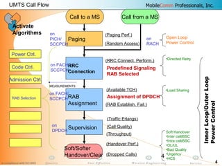
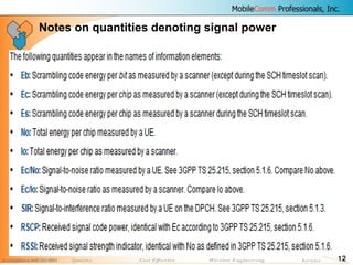
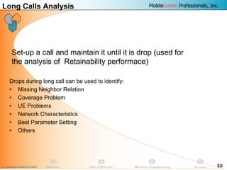
COVERAGE VERIFICATION - Primary Common
Pilot Channel
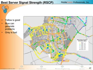
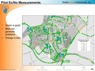
Verify P-CPICH detection to minimize coverage holes
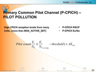
• P-CPICH RSCP
• P-CPICH Ec/No
Coverage level RSCP [dBm] Ec
/N0
[dB]
Sufficient RSCP ≥ −100 Ec
/N0
≥ −14
Poor −115 ≤ RSCP <−100 −16 ≤ Ec
/N0
< −14
No coverage RSCP < −115 Ec
/N0
<−16](https://image.slidesharecdn.com/da45f30f-ed00-4c24-9a02-5b7641224b7a-160626050837/85/08-DRIVE-TEST-Analysis-16-320.jpg)
![19
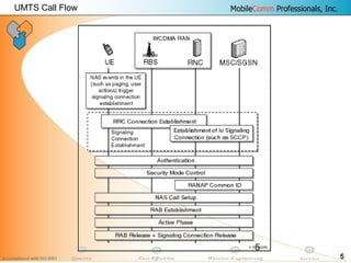
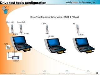
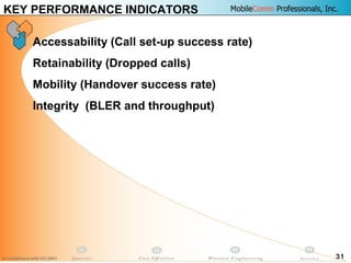
INTERFERNECE
-100
-90
-80
-70
-60
-50
-40
-30
-25 -20 -15 -10 -5 0 5
Ec/Io [dB]
RSCP[dBm]
High interference
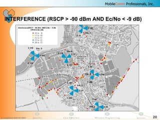
By correlating low Ec/No with high RSCP, areas with high
interference can be detected](https://image.slidesharecdn.com/da45f30f-ed00-4c24-9a02-5b7641224b7a-160626050837/85/08-DRIVE-TEST-Analysis-19-320.jpg)

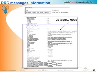
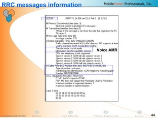
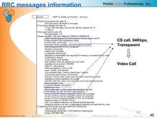
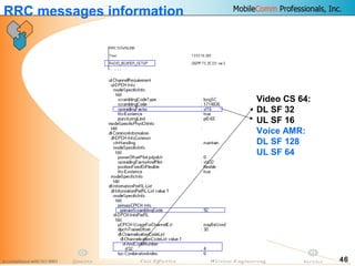


This document provides information about MobileComm Technologies' drive test process for UMTS networks. It includes documentation on tools used for tuning and optimization, parameters measured, call flows, key performance indicators, examples of coverage and interference issues identified, and tips for network tuning. The document contains 47 slides covering topics like coverage verification using P-CPICH measurements, identifying interference and overshooting issues, analyzing call drops, tuning for voice and data calls, and comparing mechanical vs electrical antenna tilts.


