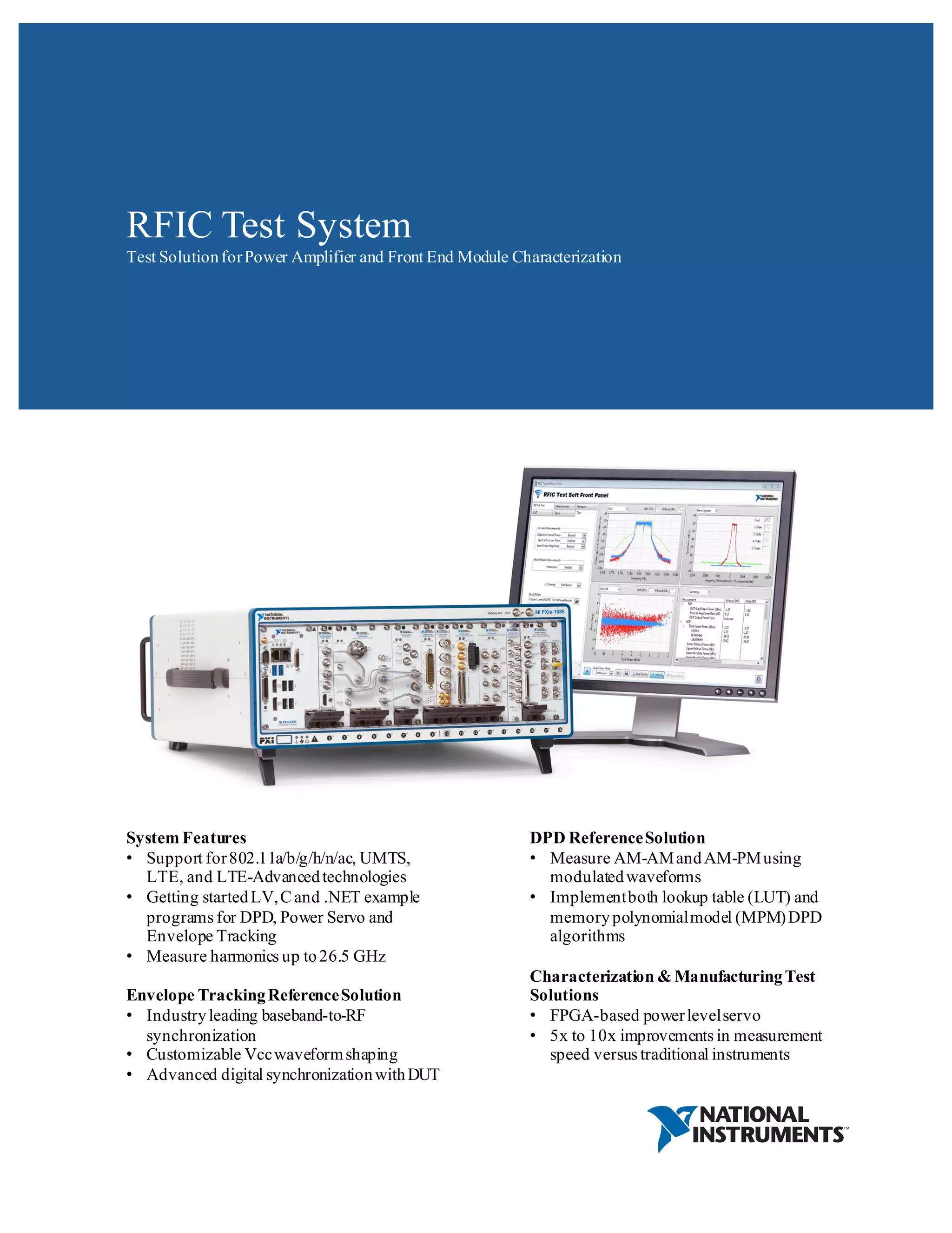
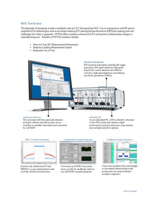
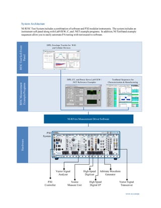
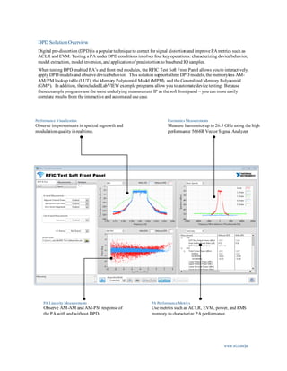
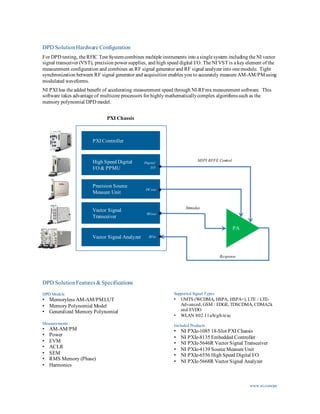
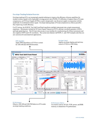
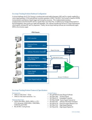
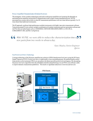
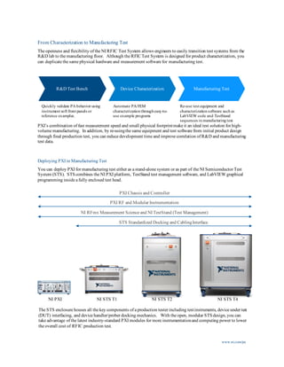
RFIC Test System
Test SolutionforPower Amplifier and Front End Module Characterization
DPD ReferenceSolution
• Measure AM-AMandAM-PMusing
modulatedwaveforms
• Implementboth lookup table (LUT) and
memorypolynomialmodel (MPM)DPD
algorithms
Characterization & ManufacturingTest
Solutions
• FPGA-based powerlevelservo
• 5x to 10x improvements in measurement
speed versus traditional instruments
System Features
• Support for802.11a/b/g/h/n/ac, UMTS,
LTE, and LTE-Advancedtechnologies
• Getting startedLV,C and .NET example
programs for DPD, Power Servo and
Envelope Tracking
• Measure harmonics up to26.5 GHz
Envelope TrackingReferenceSolution
• Industryleading baseband-to-RF
synchronization
• Customizable Vccwaveformshaping
• Advanced digital synchronizationwithDUT
TestStand Example Sequences
Transition test plans from initial design
to automated characterization and
production test using TestStand
example sequences.
RFIC Test Soft Front Panel
Interactively characterizeET and
DPD PA’s using measurements such
as EVM, ACLR, and harmonics.
www.ni.com/pa
Modular Instruments
PXI modular instruments including RF signal
generators, RF signal analyzers, high speed
digital I/O, source measureunits (SMUs),
switches, high-speed digitizers, and arbitrary
waveform generators (AWGs).
Application Software
NI instrument soft front panel and reference
example software provides an easy-to-use
interface to modular instruments and is powered
by LabVIEW
Embedded PC
As an embedded PC, a PXI controller is the heart
of the PXI system and contains a high-
performance multicore processor, deep memory,
and multiplehard drive options.
RFIC Test System
The demands of emerging wireless standards such as LTE Advanced and 802.11ac in conjunction with RF power
amplifier (PA) technologies such as envelope tracking (ET) and digital pre-distortion (DPD) are creating new test
challenges for today’s engineers. NI PXI offers complete solutions for PA testing from initial product design to
manufacturing test. Benefits of NI PXI solutions include:
• Best-in-Class RF MeasurementPerformance
• Industry-Leading Measurement Speed
• Reduced Cost of Test
Customizable Example Programs
Customize your RFIC test system
more quickly by modifying ready-to-
run LabVIEW example programs.
www.ni.com/pa
System Architecture
NI RFIC Test Systemincludes a combination of software and PXI modular instruments. The systemincludes an
instrument soft panel along with LabVIEW, C,and .NET example programs. In addition,NI TestStand example
sequences allow you to easily automate PA testing with testexecutive software.
PXI
Controller
Arbitrary Waveform
Generator
Vector Signal
Analyzer
High-Speed
Digitizer
Source
Measure Unit
High Speed
Digital I/P
PXI
System
NI-RFmx Measurement Driver Software
DPD, Envelope Trackin for WiFi
and Cellular Devices
TestStand Sequences for
Characterization & Manufacturing
DPD, ET, and Power Servo LabVIEW /
.NET Reference Examples
RFICTestSoftFront
Panel
RFICMeasurement
ExamplePrograms
Hardware
Vector Signal
Transceiver
www.ni.com/pa
DPD SolutionOverview
Digital pre-distortion (DPD) is a popular technique to correct for signal distortion and improve PA metrics such as
ACLR and EVM. Testing a PA under DPD conditions involves four key operations: characterizing device behavior,
model extraction, model inversion,and applicationof predistortion to baseband IQ samples.
When testing DPD enabled PA’s and front end modules, the RFIC Test Soft FrontPanel allows youto interactively
apply DPD models and observe device behavior. This solution supportsthree DPD models,the memoryless AM-
AM/PM lookup table (LUT), the Memory Polynomial Model (MPM), and the Generalized Memory Polynomial
(GMP). In addition, the included LabVIEW example programs allow you to automate device testing. Because
these example programs use the same underlying measurement IP as the soft front panel – you can more easily
correlate results from the interactive and automated use case.
Performance Visualization
Observe improvements in spectral regrowth and
modulation quality inreal time.
PA Linearity Measurements
Observe AM-AM and AM-PM response of
the PA with and without DPD.
PA Performance Metrics
Use metrics such as ACLR, EVM, power, and RMS
memory to characterize PA performance.
Harmonics Measurements
Measure harmonics up to 26.5 GHz using the high
performance 5668R Vector Signal Analyzer
www.ni.com/pa
DPD SolutionHardware Configuration
For DPD testing, the RFIC Test Systemcombines multiple instruments into a single system including the NI vector
signal transceiver (VST), precision power supplies, and high speed digital I/O. The NI VST is a key element of the
measurement configuration and combines an RF signal generator and RF signal analyzer into one module. Tight
synchronization between RF signal generator and acquisition enables you to accurately measure AM-AM/PMusing
modulated waveforms.
NI PXI has the added benefit of accelerating measurement speed through NI-RFmx measurement software. This
software takes advantage of multicore processors for highly mathematicallycomplex algorithmssuch as the
memory polynomial DPD model.
DPD SolutionFeatures &Specifications
DPD Models
• Memoryless AM-AM/PMLUT
• Memory Polynomial Model
• Generalized Memory Polynomial
Measurements
• AM-AM/PM
• Power
• EVM
• ACLR
• SEM
• RMS Memory (Phase)
• Harmonics
Supported Signal Types
• UMTS (WCDMA, HSPA, HSPA+), LTE / LTE-
Advanced, GSM / EDGE, TDSCDMA, CDMA2k
and EVDO
• WLAN 802.11a/b/g/h/n/ac
Included Products
• NI PXIe-1085 18-Slot PXI Chassis
• NI PXIe-8135 Embedded Controller
• NI PXIe-5646R Vector Signal Transceiver
• NI PXIe-4139 Source Measure Unit
• NI PXIe-6556 High Speed Digital I/O
• NI PXIe-5668R Vector Signal Analyzer
Vector Signal
Transceiver
PXI Chassis
MIPI RFFE ControlHigh Speed Digital
I/O & PPMU
Digital
I/O
Precision Source
Measure Unit
DCout
PA
Stimulus
Response
Vector Signal Analyzer
PXI Controller
RFin
RFout
www.ni.com/pa
Envelope TrackingSolution Overview
Envelope tracking (ET) is an increasingly popular technique to improve the efficiency of power amplifiers for
modern wireless signals with a high peak to average power ratio (PAPR). PA efficiency is highest when a PA nears
compression, an ET Power Supply (ETPS) is used to dynamically vary the power supply inconjunction withthe
amplitude of a modulated wireless signal. Envelope tracking keeps a PA near compression as often as possible –
thus improving overall efficiency.
For ET testing, the NI RFIC Test Soft FrontPanel transforms multiple instruments into a single measurement
experience. Instruments include the NI Vector Signal Transceiver (VST), arbitrary waveform generator (AWG),
and high-speed digitizer. The GUI provides an easy-to-use interface for synchronizing all of these instruments and
also supplies UMTS and LTE waveforms. The system also features LabVIEW, C, and .NETexample code that you
can customize for automated test applications.
DPD Algorithms
Apply DPD algorithms to ET PAs to correct
for AM-AM and AM-PM distortion.
Envelope Control
Applies envelope shaping and real-time
control of VSG-to-AWG delay.
PA Performance
Observe AM-AM and AM-PM behavior of PA under
envelope tracking conditions.
PA Performance Metrics
Use metrics such as ACLR, EVM, power, and RMS
memory to characterize PA performance.
www.ni.com/pa
Envelope TrackingSolution Hardware Configuration
A critical challenge for ET PA Testing is synchronizationand stable alignment of RF and Vcc signals supplied by a
vector signal generator (VSG) and arbitrary waveform generator (AWG). The RFIC Test System is based on NI PXI
instrumentation and features shared trigger and timing bus resources. This implementation produces
synchronization jitter between RF and Vcc signals that is less than 20 ps. In addition,by routing timingsignalson
the PXI backplane, these results are stable and repeatable. The software includes the NI Fast ET Align measurement
which rapidly estimates RF and Vcc alignment. Finally, the envelope tracking software can simultaneously apply
DPD to the stimulus signal.
Envelope TrackingSolution Features & Specifications
Vector Signal
Transceiver
High Speed Digitizer
Measure PA Behavior
High Speed Digital
I/O & PPMU
Arbitrary Waveform Generator
Precision Power
Supply
PXI Controller
Power
Modulator
RFout
PXI Chassis
Digital
I/O
DCout
Vcc
Out
Ch1
Ch0
PA
MIPI RFFE Control
Splitter
Shaped Envelope
Synchronization
• AWG-to-VSG Jitter: < 20 ps
• AWG-to-VSG skew resolution: 1 ns
Supported Signal Types
• UMTS (WCDMA, HSPA, HSPA+), LTE /
LTE-Advanced, GSM/EDGE, TDSCDMA,
CDMA2k and EVDO
• WLAN 802.11a/b/g/h/n/ac
Included Products
• NI LabVIEW System Design Software
• NI PXIe-1085 18-SlotChassis
• NI PXIe-8135 Embedded Controller
• NI PXIe-5646R Vector Signal Transceiver
• NI PXIe-5451 Arbitrary Waveform Generator
• NI PXIe-4139 Precision Source Measure Unit
• NI PXIe-5162 High Speed Digitizer
• NI PXIe-6556 High Speed Digital I/O
Vector Signal Analyzer RFin
Power Amplifier CharacterizationSolutionOverview
The emergence of new wireless technologies and multi-mode power amplifiers are increasing the demands on
automated power amplifier testing both in characterization and in high-volume manufacturing test.NI PXI
automated test systems deliver best-in-class RFmeasurement performance with test times that are typically 5 to 10
times faster than traditional instruments.
The NI approach combines high-performance modular instrumentswith highly innovative measurement software.
Typical automated PA test systems include a combinationof modular instrumentsand test automation software and
test PAs that use technologies such as: GSM/EDGE,UMTS(WCDMA/HSPA/HSPA+), LTE/LTE-A,
CDMA2000/EV-DO, and 802.11a/b/g/h/n/ac
With NI PXI, we were able to reduce the characterization time of
new parts from two weeks to about a day.
Gary Shipley, SeniorEngineer
Qorvo
www.ni.com/pa
“ ”
Fast Power Level Servo Technology
A unique technology of the NI power amplifier test solution isFPGA-based power level servo using the NI Vector
Signal Transceiver (VST). Power level servo is traditionally a time consuming process.By performingthe control
loop entirely on the instrument FPGA you can achieve the fastest possible power level convergence. By decoupling
the power level servo algorithm from the embedded controller and performing it on an FPGA,test software is able
to exploit dramatic measurement parallelism. Thisresults in significant reductions in testtime and test cost.
Vector Signal Transceiver
Digital
I/O
RFin
RFout
PXI Chassis
FPGA
PA
Data Transfer
PXI Controller
CPU Memory
From Characterization to Manufacturing Test
The openness and flexibility of the NI RFIC Test System allows engineers to easily transition test systems from the
R&D lab to the manufacturing floor. Although the RFICTest System is designed for product characterization, you
can duplicate the same physical hardware and measurement software for manufacturing test.
PXI’s combination of fast measurement speed and small physical footprintmake it an ideal test solution for high-
volume manufacturing. In addition, by re-usingthe same equipment and test software from initial product design
through final production test, you can reduce development time and improve correlation of R&D and manufacturing
test data.
Quickly validate PA behavior using
instrument soft front panels or
reference examples.
Automate PA/FEM
characterization through easy-to-
use example programs
Re-use test equipment and
characterization software such as
LabVIEW code and TestStand
sequences in manufacturing test.
www.ni.com/pa
R&D Test Bench Device Characterization Manufacturing Test
NI STS T1NI PXI NI STS T4NI STS T2
PXI Chassis and Controller
PXI RF and Modular Instrumentation
NI RFmx Measurement Science and NI TestStand (Test Management)
STS Standardized Docking and CablingInterface
Deploying PXI in Manufacturing Test
You can deploy PXI for manufacturing test either as a stand-alone system or as part of the NI Semiconductor Test
System (STS). STScombines the NI PXI platform, TestStand test management software, and LabVIEW graphical
programming inside a fully enclosed test head.
The STS enclosure houses all the key components of a production tester including testinstruments, device under test
(DUT) interfacing, and device handler/prober docking mechanics. With the open, modular STSdesign,you can
take advantage of the latest industry-standard PXI modules for more instrumentationand computing power to lower
the overall cost of RFIC production test.
www.ni.com/pa
Hardware Specifications
NI DPD and Envelope Tracking (ET) Reference Solutions are based on a standard configuration of PXI modular
instruments. One can use these instruments with the LabVIEW Reference example code or as standalone
instruments.
NI PXIe-5646R Vector Signal Transceiver
The NI PXIE-5646R VST combines an RFvector
signal generator (VSG) and RF vector signal
analyzer (VSA) into one module. The combination
of wide bandwidth and high-quality RF
measurement performance make the NI PXIe-5646R
an ideal solution for RF power amplifier testing.
PXIe-5646R Specifications (Signal Generator)
Frequency Range 65 MHz – 6 GHz
Bandwidth 200 MHz
Maximum Output Power +15 dBm
802.11acEVM -45 dB
LTE EVM -50 dB
UMTS ACLR 65 dB
PXIe-5646R Specifications (Signal Analyzer)
Frequency Range 65 MHz – 6 GHz
Bandwidth 200 MHz
Amplitude Accuracy +/- 0.34 dB
Average Noise Floor -161 dBm/Hz (1 GHz)
802.11acEVM -45 dB
LTE EVM -50 dB
Refer to PXIe-5646R Specifications Document for more details
PXIe-55668R Specifications
Frequency Range 20 Hz – 26.5 GHz
Bandwidth Up to 765 MHz
Phase Noise, Typ -129 dBm/Hz ( 1GHz)
Amplitude Accuracy +/- 0.25 dB
Average Noise Floor -167 dBM/Hz (1 GHz)
Tuning Speed 3 ms (1 GHz step)
Third Order Intercept +25 dBm (1 GHz)
Refer to PXIe-5668R Specifications Document for more details
NI PXIe-5668R Vector Signal Transceiver
www.ni.com/pa
Hardware Specifications (Continued)
PXIe-8880 Embedded Controller Specifications
Processor Xeon Octal Core
CPU Clock Rate 2.3 GHz
Memory Up to 24 GB
PXIe-1085 Chassis Specifications
PXI Express Slots 18
Total System Bandwidth 24 GB/s
Total Power Rating 925 W
PXIe-6556 High SpeedDIO Specifications
Clock Rates 800 Hz – 200 MHz
PPMU Channels 24
Voltage Ranges -2 V to 7 V
PXIe-5162 10-BitDigitizer Specifications
Max Sample Rate 5 GS/s
Bandwidth (3 dB) 1.5 GHz
Max Channels 4
PXIe-5451 Arbitrary Waveform Generator
Specifications
Max Sample Rate 400 MS/s
Bandwidth 145 MHz
SFDR (1 MHz) 98 dB
PXIe-4139 Precision Source Measure Unit
Specifications
Max Pulse Power 500 W
Max Continuous Power 20 W
Transient Response < 70 µs
©2013 National Instruments. All rights reserved. LabVIEW, National Instruments, NI, ni.com, and NI CompactDAQ are trademarks of National
Instruments. Other product and companynames listedare trademarksor trade names
of their respective companies. [20160729]
For more informationonthe RFIC Test system, email: rfic.test@ni.com

STS RF IC Test System

  • 1.
    RFIC Test System TestSolutionforPower Amplifier and Front End Module Characterization DPD ReferenceSolution • Measure AM-AMandAM-PMusing modulatedwaveforms • Implementboth lookup table (LUT) and memorypolynomialmodel (MPM)DPD algorithms Characterization & ManufacturingTest Solutions • FPGA-based powerlevelservo • 5x to 10x improvements in measurement speed versus traditional instruments System Features • Support for802.11a/b/g/h/n/ac, UMTS, LTE, and LTE-Advancedtechnologies • Getting startedLV,C and .NET example programs for DPD, Power Servo and Envelope Tracking • Measure harmonics up to26.5 GHz Envelope TrackingReferenceSolution • Industryleading baseband-to-RF synchronization • Customizable Vccwaveformshaping • Advanced digital synchronizationwithDUT
  • 2.
    TestStand Example Sequences Transitiontest plans from initial design to automated characterization and production test using TestStand example sequences. RFIC Test Soft Front Panel Interactively characterizeET and DPD PA’s using measurements such as EVM, ACLR, and harmonics. www.ni.com/pa Modular Instruments PXI modular instruments including RF signal generators, RF signal analyzers, high speed digital I/O, source measureunits (SMUs), switches, high-speed digitizers, and arbitrary waveform generators (AWGs). Application Software NI instrument soft front panel and reference example software provides an easy-to-use interface to modular instruments and is powered by LabVIEW Embedded PC As an embedded PC, a PXI controller is the heart of the PXI system and contains a high- performance multicore processor, deep memory, and multiplehard drive options. RFIC Test System The demands of emerging wireless standards such as LTE Advanced and 802.11ac in conjunction with RF power amplifier (PA) technologies such as envelope tracking (ET) and digital pre-distortion (DPD) are creating new test challenges for today’s engineers. NI PXI offers complete solutions for PA testing from initial product design to manufacturing test. Benefits of NI PXI solutions include: • Best-in-Class RF MeasurementPerformance • Industry-Leading Measurement Speed • Reduced Cost of Test Customizable Example Programs Customize your RFIC test system more quickly by modifying ready-to- run LabVIEW example programs.
  • 3.
    www.ni.com/pa System Architecture NI RFICTest Systemincludes a combination of software and PXI modular instruments. The systemincludes an instrument soft panel along with LabVIEW, C,and .NET example programs. In addition,NI TestStand example sequences allow you to easily automate PA testing with testexecutive software. PXI Controller Arbitrary Waveform Generator Vector Signal Analyzer High-Speed Digitizer Source Measure Unit High Speed Digital I/P PXI System NI-RFmx Measurement Driver Software DPD, Envelope Trackin for WiFi and Cellular Devices TestStand Sequences for Characterization & Manufacturing DPD, ET, and Power Servo LabVIEW / .NET Reference Examples RFICTestSoftFront Panel RFICMeasurement ExamplePrograms Hardware Vector Signal Transceiver
  • 4.
    www.ni.com/pa DPD SolutionOverview Digital pre-distortion(DPD) is a popular technique to correct for signal distortion and improve PA metrics such as ACLR and EVM. Testing a PA under DPD conditions involves four key operations: characterizing device behavior, model extraction, model inversion,and applicationof predistortion to baseband IQ samples. When testing DPD enabled PA’s and front end modules, the RFIC Test Soft FrontPanel allows youto interactively apply DPD models and observe device behavior. This solution supportsthree DPD models,the memoryless AM- AM/PM lookup table (LUT), the Memory Polynomial Model (MPM), and the Generalized Memory Polynomial (GMP). In addition, the included LabVIEW example programs allow you to automate device testing. Because these example programs use the same underlying measurement IP as the soft front panel – you can more easily correlate results from the interactive and automated use case. Performance Visualization Observe improvements in spectral regrowth and modulation quality inreal time. PA Linearity Measurements Observe AM-AM and AM-PM response of the PA with and without DPD. PA Performance Metrics Use metrics such as ACLR, EVM, power, and RMS memory to characterize PA performance. Harmonics Measurements Measure harmonics up to 26.5 GHz using the high performance 5668R Vector Signal Analyzer
  • 5.
    www.ni.com/pa DPD SolutionHardware Configuration ForDPD testing, the RFIC Test Systemcombines multiple instruments into a single system including the NI vector signal transceiver (VST), precision power supplies, and high speed digital I/O. The NI VST is a key element of the measurement configuration and combines an RF signal generator and RF signal analyzer into one module. Tight synchronization between RF signal generator and acquisition enables you to accurately measure AM-AM/PMusing modulated waveforms. NI PXI has the added benefit of accelerating measurement speed through NI-RFmx measurement software. This software takes advantage of multicore processors for highly mathematicallycomplex algorithmssuch as the memory polynomial DPD model. DPD SolutionFeatures &Specifications DPD Models • Memoryless AM-AM/PMLUT • Memory Polynomial Model • Generalized Memory Polynomial Measurements • AM-AM/PM • Power • EVM • ACLR • SEM • RMS Memory (Phase) • Harmonics Supported Signal Types • UMTS (WCDMA, HSPA, HSPA+), LTE / LTE- Advanced, GSM / EDGE, TDSCDMA, CDMA2k and EVDO • WLAN 802.11a/b/g/h/n/ac Included Products • NI PXIe-1085 18-Slot PXI Chassis • NI PXIe-8135 Embedded Controller • NI PXIe-5646R Vector Signal Transceiver • NI PXIe-4139 Source Measure Unit • NI PXIe-6556 High Speed Digital I/O • NI PXIe-5668R Vector Signal Analyzer Vector Signal Transceiver PXI Chassis MIPI RFFE ControlHigh Speed Digital I/O & PPMU Digital I/O Precision Source Measure Unit DCout PA Stimulus Response Vector Signal Analyzer PXI Controller RFin RFout
  • 6.
    www.ni.com/pa Envelope TrackingSolution Overview Envelopetracking (ET) is an increasingly popular technique to improve the efficiency of power amplifiers for modern wireless signals with a high peak to average power ratio (PAPR). PA efficiency is highest when a PA nears compression, an ET Power Supply (ETPS) is used to dynamically vary the power supply inconjunction withthe amplitude of a modulated wireless signal. Envelope tracking keeps a PA near compression as often as possible – thus improving overall efficiency. For ET testing, the NI RFIC Test Soft FrontPanel transforms multiple instruments into a single measurement experience. Instruments include the NI Vector Signal Transceiver (VST), arbitrary waveform generator (AWG), and high-speed digitizer. The GUI provides an easy-to-use interface for synchronizing all of these instruments and also supplies UMTS and LTE waveforms. The system also features LabVIEW, C, and .NETexample code that you can customize for automated test applications. DPD Algorithms Apply DPD algorithms to ET PAs to correct for AM-AM and AM-PM distortion. Envelope Control Applies envelope shaping and real-time control of VSG-to-AWG delay. PA Performance Observe AM-AM and AM-PM behavior of PA under envelope tracking conditions. PA Performance Metrics Use metrics such as ACLR, EVM, power, and RMS memory to characterize PA performance.
  • 7.
    www.ni.com/pa Envelope TrackingSolution HardwareConfiguration A critical challenge for ET PA Testing is synchronizationand stable alignment of RF and Vcc signals supplied by a vector signal generator (VSG) and arbitrary waveform generator (AWG). The RFIC Test System is based on NI PXI instrumentation and features shared trigger and timing bus resources. This implementation produces synchronization jitter between RF and Vcc signals that is less than 20 ps. In addition,by routing timingsignalson the PXI backplane, these results are stable and repeatable. The software includes the NI Fast ET Align measurement which rapidly estimates RF and Vcc alignment. Finally, the envelope tracking software can simultaneously apply DPD to the stimulus signal. Envelope TrackingSolution Features & Specifications Vector Signal Transceiver High Speed Digitizer Measure PA Behavior High Speed Digital I/O & PPMU Arbitrary Waveform Generator Precision Power Supply PXI Controller Power Modulator RFout PXI Chassis Digital I/O DCout Vcc Out Ch1 Ch0 PA MIPI RFFE Control Splitter Shaped Envelope Synchronization • AWG-to-VSG Jitter: < 20 ps • AWG-to-VSG skew resolution: 1 ns Supported Signal Types • UMTS (WCDMA, HSPA, HSPA+), LTE / LTE-Advanced, GSM/EDGE, TDSCDMA, CDMA2k and EVDO • WLAN 802.11a/b/g/h/n/ac Included Products • NI LabVIEW System Design Software • NI PXIe-1085 18-SlotChassis • NI PXIe-8135 Embedded Controller • NI PXIe-5646R Vector Signal Transceiver • NI PXIe-5451 Arbitrary Waveform Generator • NI PXIe-4139 Precision Source Measure Unit • NI PXIe-5162 High Speed Digitizer • NI PXIe-6556 High Speed Digital I/O Vector Signal Analyzer RFin
  • 8.
    Power Amplifier CharacterizationSolutionOverview Theemergence of new wireless technologies and multi-mode power amplifiers are increasing the demands on automated power amplifier testing both in characterization and in high-volume manufacturing test.NI PXI automated test systems deliver best-in-class RFmeasurement performance with test times that are typically 5 to 10 times faster than traditional instruments. The NI approach combines high-performance modular instrumentswith highly innovative measurement software. Typical automated PA test systems include a combinationof modular instrumentsand test automation software and test PAs that use technologies such as: GSM/EDGE,UMTS(WCDMA/HSPA/HSPA+), LTE/LTE-A, CDMA2000/EV-DO, and 802.11a/b/g/h/n/ac With NI PXI, we were able to reduce the characterization time of new parts from two weeks to about a day. Gary Shipley, SeniorEngineer Qorvo www.ni.com/pa “ ” Fast Power Level Servo Technology A unique technology of the NI power amplifier test solution isFPGA-based power level servo using the NI Vector Signal Transceiver (VST). Power level servo is traditionally a time consuming process.By performingthe control loop entirely on the instrument FPGA you can achieve the fastest possible power level convergence. By decoupling the power level servo algorithm from the embedded controller and performing it on an FPGA,test software is able to exploit dramatic measurement parallelism. Thisresults in significant reductions in testtime and test cost. Vector Signal Transceiver Digital I/O RFin RFout PXI Chassis FPGA PA Data Transfer PXI Controller CPU Memory
  • 9.
    From Characterization toManufacturing Test The openness and flexibility of the NI RFIC Test System allows engineers to easily transition test systems from the R&D lab to the manufacturing floor. Although the RFICTest System is designed for product characterization, you can duplicate the same physical hardware and measurement software for manufacturing test. PXI’s combination of fast measurement speed and small physical footprintmake it an ideal test solution for high- volume manufacturing. In addition, by re-usingthe same equipment and test software from initial product design through final production test, you can reduce development time and improve correlation of R&D and manufacturing test data. Quickly validate PA behavior using instrument soft front panels or reference examples. Automate PA/FEM characterization through easy-to- use example programs Re-use test equipment and characterization software such as LabVIEW code and TestStand sequences in manufacturing test. www.ni.com/pa R&D Test Bench Device Characterization Manufacturing Test NI STS T1NI PXI NI STS T4NI STS T2 PXI Chassis and Controller PXI RF and Modular Instrumentation NI RFmx Measurement Science and NI TestStand (Test Management) STS Standardized Docking and CablingInterface Deploying PXI in Manufacturing Test You can deploy PXI for manufacturing test either as a stand-alone system or as part of the NI Semiconductor Test System (STS). STScombines the NI PXI platform, TestStand test management software, and LabVIEW graphical programming inside a fully enclosed test head. The STS enclosure houses all the key components of a production tester including testinstruments, device under test (DUT) interfacing, and device handler/prober docking mechanics. With the open, modular STSdesign,you can take advantage of the latest industry-standard PXI modules for more instrumentationand computing power to lower the overall cost of RFIC production test.
  • 10.
    www.ni.com/pa Hardware Specifications NI DPDand Envelope Tracking (ET) Reference Solutions are based on a standard configuration of PXI modular instruments. One can use these instruments with the LabVIEW Reference example code or as standalone instruments. NI PXIe-5646R Vector Signal Transceiver The NI PXIE-5646R VST combines an RFvector signal generator (VSG) and RF vector signal analyzer (VSA) into one module. The combination of wide bandwidth and high-quality RF measurement performance make the NI PXIe-5646R an ideal solution for RF power amplifier testing. PXIe-5646R Specifications (Signal Generator) Frequency Range 65 MHz – 6 GHz Bandwidth 200 MHz Maximum Output Power +15 dBm 802.11acEVM -45 dB LTE EVM -50 dB UMTS ACLR 65 dB PXIe-5646R Specifications (Signal Analyzer) Frequency Range 65 MHz – 6 GHz Bandwidth 200 MHz Amplitude Accuracy +/- 0.34 dB Average Noise Floor -161 dBm/Hz (1 GHz) 802.11acEVM -45 dB LTE EVM -50 dB Refer to PXIe-5646R Specifications Document for more details PXIe-55668R Specifications Frequency Range 20 Hz – 26.5 GHz Bandwidth Up to 765 MHz Phase Noise, Typ -129 dBm/Hz ( 1GHz) Amplitude Accuracy +/- 0.25 dB Average Noise Floor -167 dBM/Hz (1 GHz) Tuning Speed 3 ms (1 GHz step) Third Order Intercept +25 dBm (1 GHz) Refer to PXIe-5668R Specifications Document for more details NI PXIe-5668R Vector Signal Transceiver
  • 11.
    www.ni.com/pa Hardware Specifications (Continued) PXIe-8880Embedded Controller Specifications Processor Xeon Octal Core CPU Clock Rate 2.3 GHz Memory Up to 24 GB PXIe-1085 Chassis Specifications PXI Express Slots 18 Total System Bandwidth 24 GB/s Total Power Rating 925 W PXIe-6556 High SpeedDIO Specifications Clock Rates 800 Hz – 200 MHz PPMU Channels 24 Voltage Ranges -2 V to 7 V PXIe-5162 10-BitDigitizer Specifications Max Sample Rate 5 GS/s Bandwidth (3 dB) 1.5 GHz Max Channels 4 PXIe-5451 Arbitrary Waveform Generator Specifications Max Sample Rate 400 MS/s Bandwidth 145 MHz SFDR (1 MHz) 98 dB PXIe-4139 Precision Source Measure Unit Specifications Max Pulse Power 500 W Max Continuous Power 20 W Transient Response < 70 µs
  • 12.
    ©2013 National Instruments.All rights reserved. LabVIEW, National Instruments, NI, ni.com, and NI CompactDAQ are trademarks of National Instruments. Other product and companynames listedare trademarksor trade names of their respective companies. [20160729] For more informationonthe RFIC Test system, email: rfic.test@ni.com