Downloaded 137 times
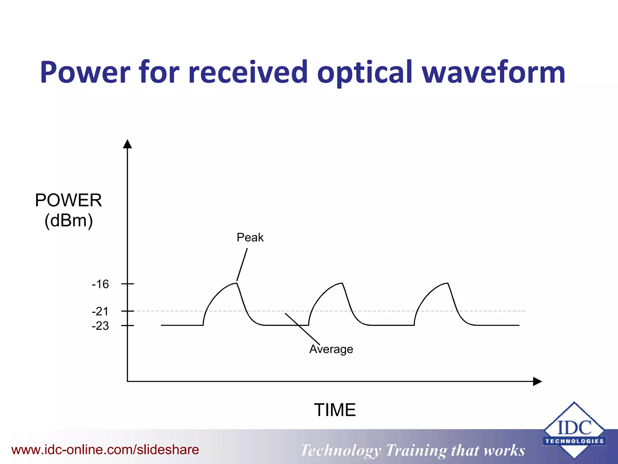

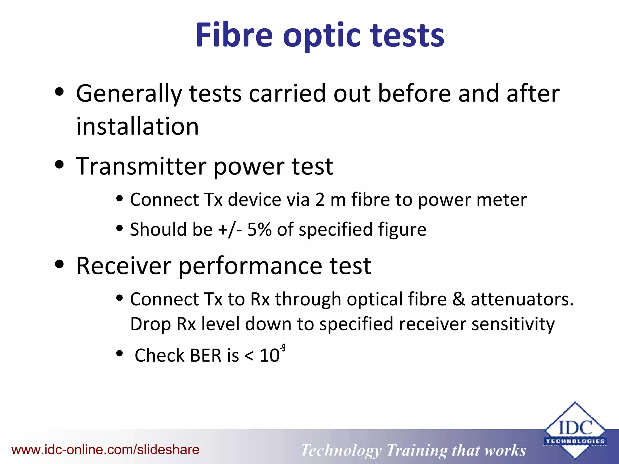
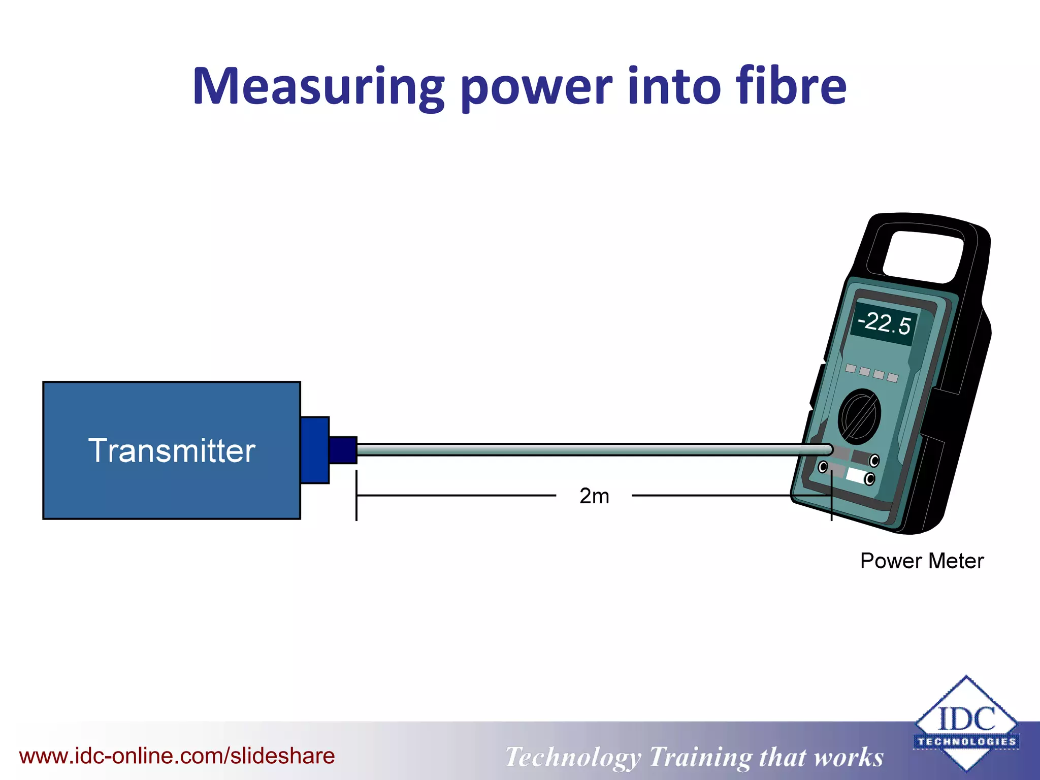
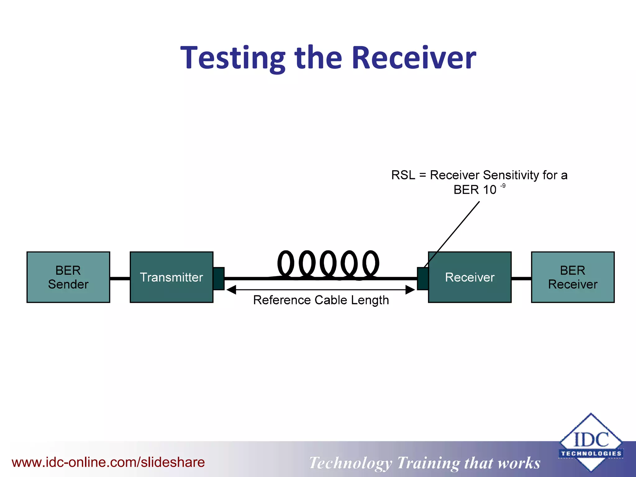
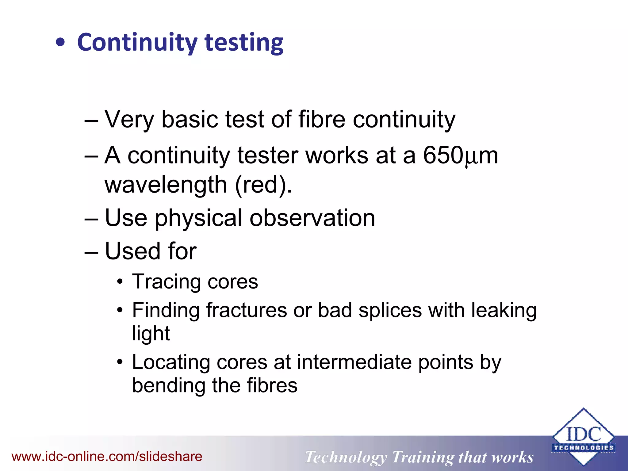
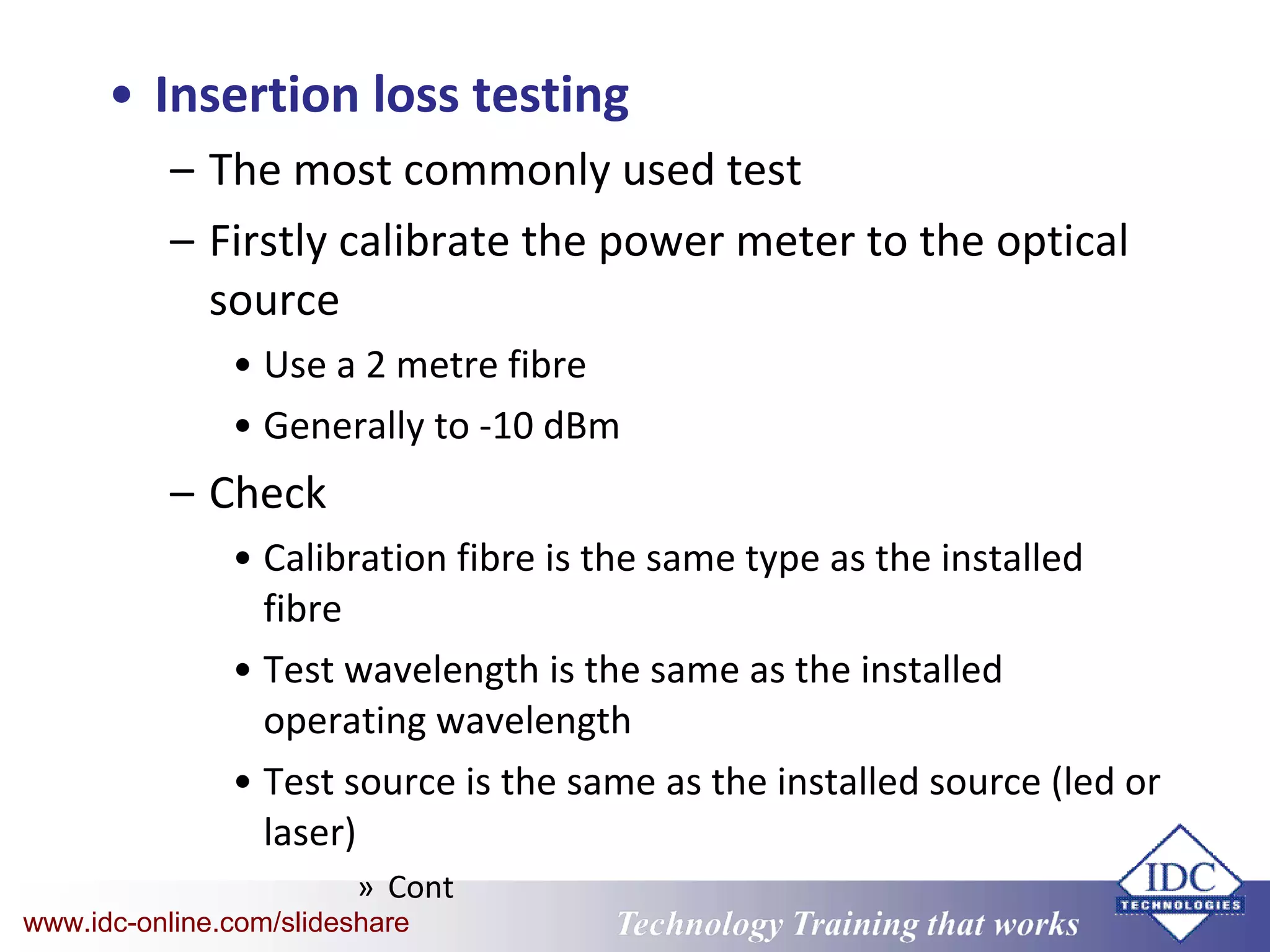
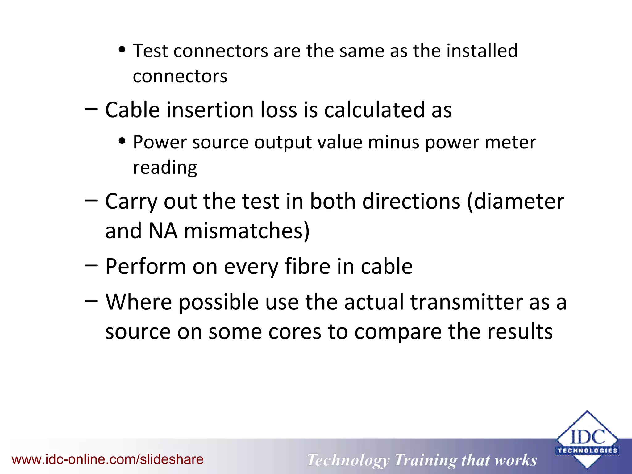
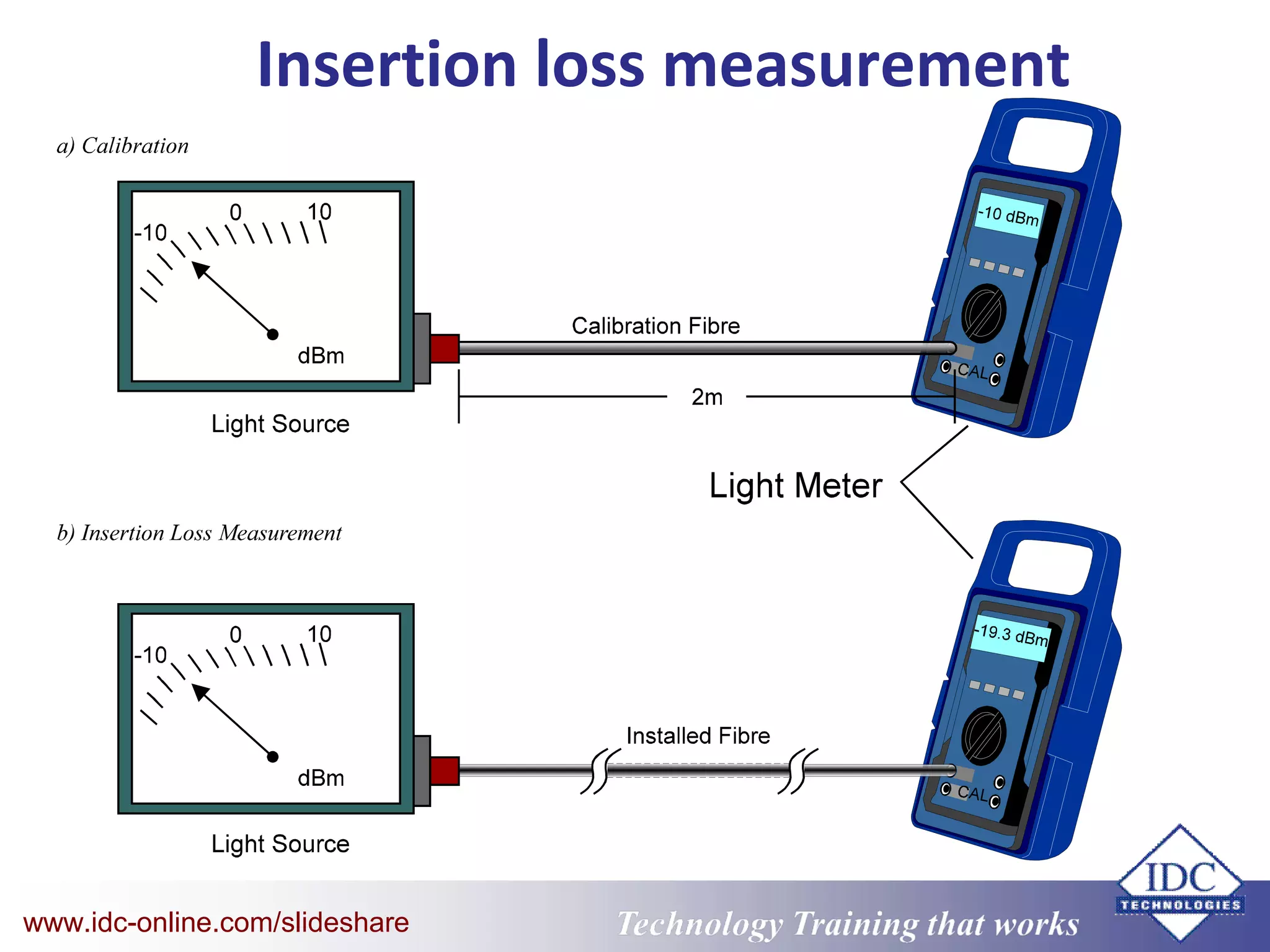
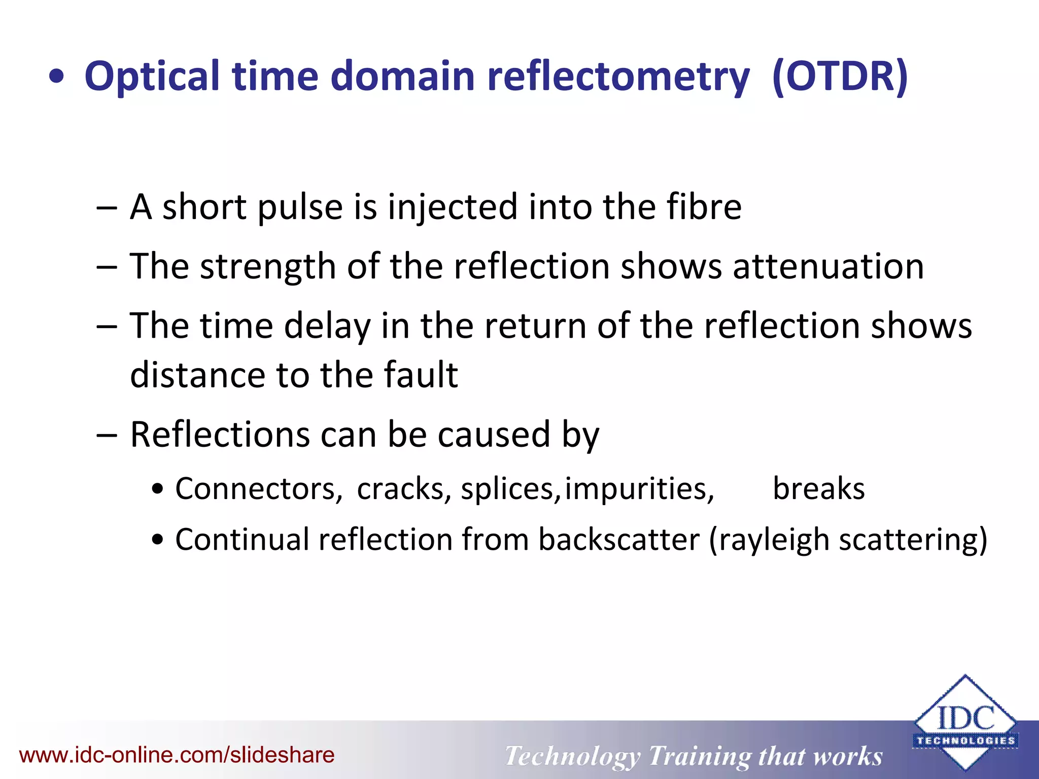
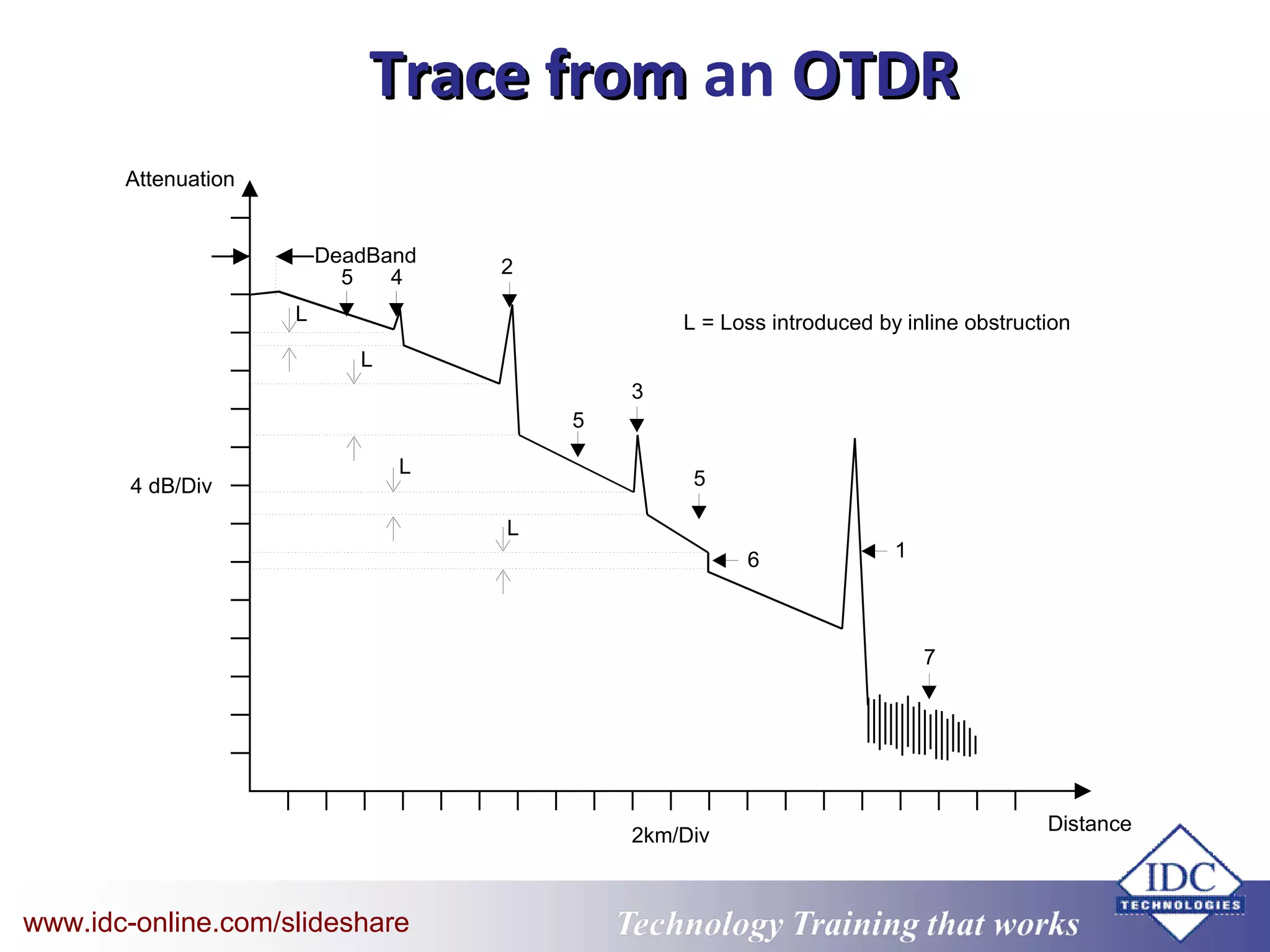
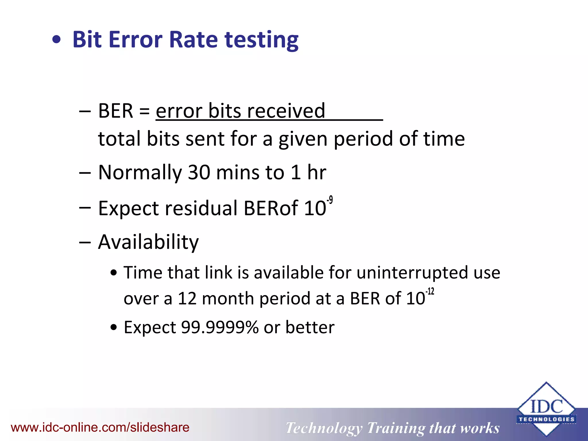
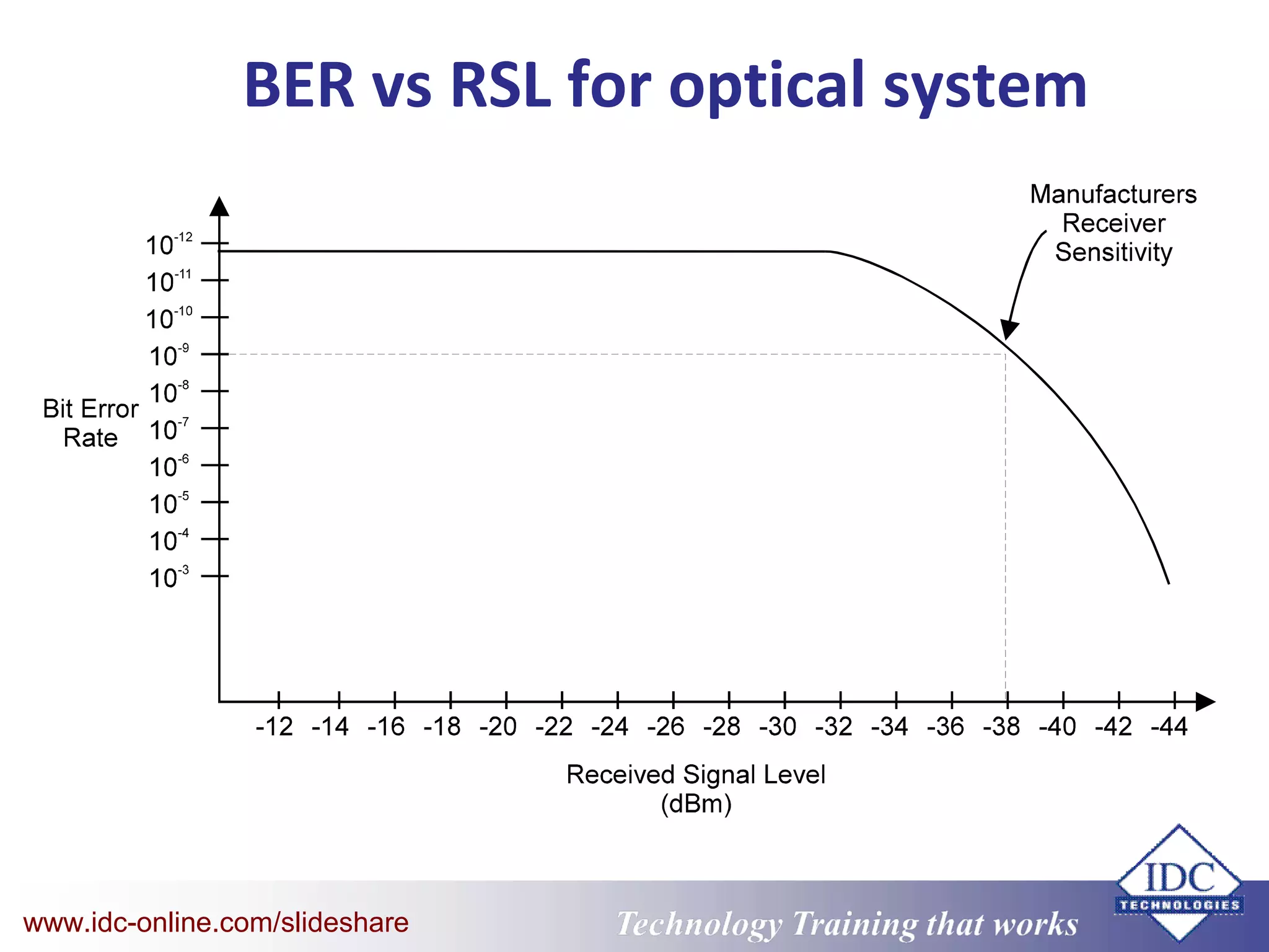
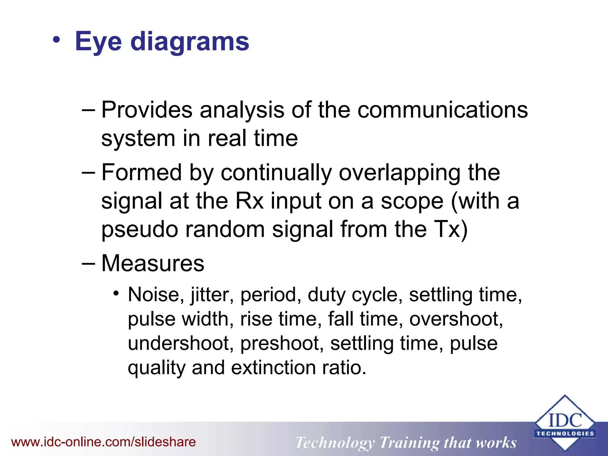
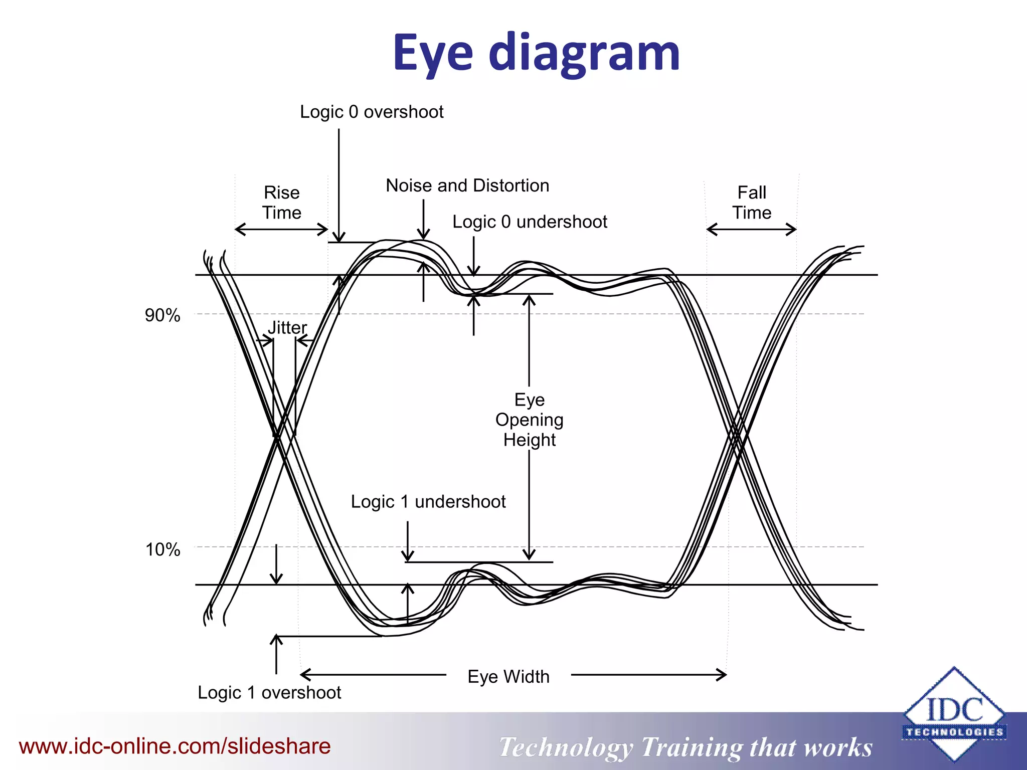

This document discusses testing and troubleshooting of fibre optic cables. It outlines various standard fibre optic cable and equipment tests including transmitter power tests, receiver performance tests, continuity testing, insertion loss testing, and optical time domain reflectometry. It also discusses bit error rate testing, eye diagram analysis, and various laboratory measurements of fibre optic cables and equipment. More information is available at http://www.idc-online.com/slideshare.


