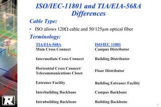
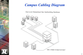
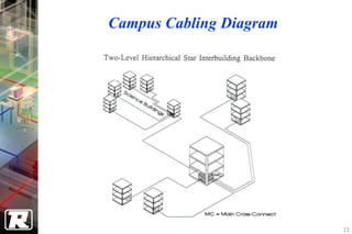
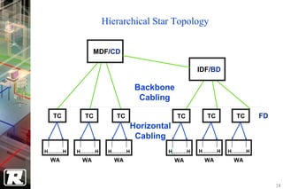
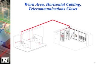
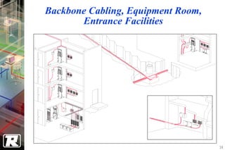
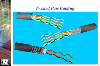
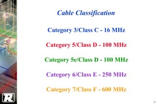
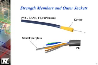
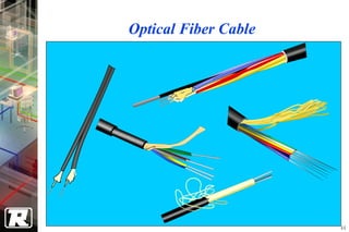
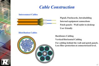
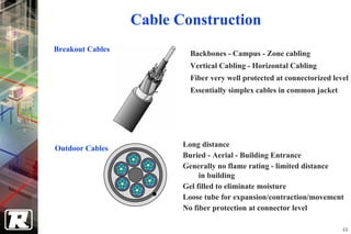
Introduction to
PREMISES CABLING SYSTEM


                          1
Standards
                               ISO

CENELEC AS/NZS                 ANSI             IEC           CSA

                         TIA          EIA

EN50173   AS/NZS 3080     TIA/EIA-568A      ISO/IEC 11801    CSA T 529

           AS 3084         TIA/EIA-569                      CSA T 530

           AS/NZS 3085     TIA/EIA-606                      CSA T 529

                           TIA/EIA-607                      CSA T 528

                                                                         2
Benefits of Standards Compliance

• Assurance that cabling system will support
  standards-based applications
   − Future network applications will most likely be
     developed based on infrastructure standards

• Simplify administration
   − Reduce Total Cost of Ownership (TCO)

• Accommodate future growth


                                                       3
ISO/IEC-11801
• Generic cabling for customer premises Standard
   − Approved and released in 1995
   − The de-facto standard that all other organizations model their
     standards after
• Purpose
   − To provide a world standard for the design, installation, and
     administration of commercial building telecommunications
     systems.


                                                                      4
TIA/EIA-568A
• Commercial Building Telecommunications Cabling
  Standard
  − EIA/TIA-568 - July 1991
  − TIA/EIA-568A - October 1995
  − EIA/TIA-568B - 2000
• Purpose
  − To enable the planning and installation of a structured cabling
    system for commercial buildings...
  − ...specifying a generic telecommunications cabling system that
    will support a multi-product, multi-vendor environment


                                                                      5
ISO/IEC-11801 and TIA/EIA-568A
             Overview
Major sections include:
• Definitions, Acronyms, Abbreviations
• Horizontal and Backbone Cabling
• Telecommunications Closets, Equipment Rooms,
  Building Entrance Facilities
• Unshielded Twisted Pair, Shielded Twisted Pair and
  Optical Fiber Cabling and Connecting Hardware
• Shielding Practices
• Link Specifications and Testing

                                                       6
ISO/IEC-11801 and TIA/EIA-568A
             Differences
Cable Type:
• ISO allows 120Ω cable and 50/125µm optical fiber
Terminology:
   TIA/EIA-568A                 ISO/IEC 11801
   Main Cross Connect           Campus Distributor

   Intermediate Cross Connect   Building Distributor

   Horizontal Cross Connect/
                                Floor Distributor
   Telecommunications Closet

   Entrance Facility            Building Entrance Facility

   Interbuilding Backbone       Campus Backbone

   Intrabuilding Backbone       Building Backbone
                                                             7
TIA/EIA-569A
• Commercial Building Standard for Telecommunications
  Pathways and Spaces
• Purpose
  − Standardize specific design and construction practices within
    and between buildings which are in support of
    telecommunications media and equipment
• Sections
  −   Horizontal Pathways
  −   Backbone Pathways
  −   Work Area
  −   Telecommunications Closet, Equipment Room, Entrance
      Facilities
                                                                    8
TIA/EIA-606
• Administration Standard for the Telecommunications
  Infrastructure of Commercial Buildings
• Purpose
  − To provide a uniform administration scheme that is
    independent of applications and establishes guidelines for
    owners, end users, manufacturers, consultants, contractors,
    designers, installers, and facilities administrators involved in
    the administration of telecommunications infrastructure
• Sections
  − Administration Concepts
  − Pathway and Space, and Grounding & Bonding Administration
  − Labeling and Color Coding
                                                                       9
TIA/EIA-607
• Commercial Building Grounding and Bonding
  Requirements for the Telecommunications Industry
• Purpose
  − To enable the planning, design, and installation of a
    telecommunications grounding system that supports a multi-
    vendor, multi-product environment as well as the grounding
    practices for various systems
• Sections
  − Grounding and Bonding Overview
  − Components of the Grounding and Bonding Infrastructure
  − Telecommunications Closet, Equipment Room, and Entrance
    Facilities
                                                                 10
Elements/Sub-Systems

• Work Area
• Horizontal Cabling
• Telecommunications Closet
• Backbone Cabling
• Equipment Room
• Entrance Facility
• Administration
                               11
Campus Cabling Diagram


                         12
Campus Cabling Diagram


                         13
Hierarchical Star Topology


              MDF/CD

                                          IDF/BD

                         Backbone
                          Cabling

  TC     TC        TC                TC     TC      TC     FD
                        Horizontal
                         Cabling
H………H   H………H    H………H           H………H    H………H    H………H
 WA      WA        WA                WA    WA       WA


                                                                14
Work Area, Horizontal Cabling,
 Telecommunications Closet


                                 15
Backbone Cabling, Equipment Room,
       Entrance Facilities


                                    16
Elements/Sub-Systems - Administration

• Work Area
• Horizontal Cabling
• Telecommunications Closet
• Backbone Cabling
• Equipment Room
• Entrance Facility
• Administration
                                        17
Twisted Pair Cabling


                       18
Cable Classification

 Category 3/Class C - 16 MHz

Category 5/Class D - 100 MHz

Category 5e/Class D - 100 MHz

Category 6/Class E - 250 MHz

Category 7/Class F - 600 MHz
                                19
Twisted Pair Types


    UTP


                                 FTP, SFTP


STP, PiMF


                                             20
Crosstalk


            21
Near End Crosstalk (NEXT)

Transmit


Receive


  • Crosstalk measures the amount of signal
    interference from one pair to another pair
  • NEXT measures crosstalk at the signal source
    (Near End)


                                                   22
Twisted Pair Construction


 22/24 AWG


                                 PVC, LSZH, FEP


22/26 AWG
(PiMF = 23 AWG, 4-pair)

                                                  23
Optical Fiber Overview

• Reflection
• Refraction
• Refractive Index
• Core/Cladding
• Numerical Aperture
• Modes
• Wavelength

                                  24
Advantages of Fiber Optics

•   Large Bandwidth
•   Low Attenuation
•   No Crosstalk
•   No Radio Freq. or Electromagnetic Emissions
•   No RFI or EMI susceptibility
•   No Ground Loops
•   Safety, no Shock or Spark Hazards
•   High Future Upgrade Capability
•   No EMP susceptibility
                                                  25
Reflection vs. Refraction


               Refraction

Source           Reflection


                                     26
Refractive Index


N2
N1


          Speed of Light (Vacuum)
     N=
          Speed of Light (Medium)

                                    27
Internal Reflection in a Fiber

                                          Cladding = n1

                           n 1 = 1.46
80.6    80.6               n 2 = 1.48

                           n 1 = 1.46

b C = sin 1.46 = 80.6°
         -1

            1.48                        Core = n 2


                                                          28
Core/Cladding
                                  Core
       Cladding                   Glass
                      Cladding    Rod
                     Glass Tube


Core

                        Heat


                                    Heat
                    Fiber
                                           29
CROSS SECTION OF A TYPICAL FIBER


                    Core

                Cladding
                 125 um
                  Coating
         250 um, 400 um or 900 um


                                    30
Numerical Aperture and Modes

          Low Order Modes   Axial Mode


Acceptance Cone         High Order Modes


                                           31
Wavelength


ATTENUATION


              850      1300/1310   1550
                    WAVELENGTH


                                          32
Optical Fiber Review

• Reflection
• Refraction
• Refractive Index
• Core/Cladding
• Numerical Aperture
• Modes
• Wavelength

                                 33
Optical Fiber Types

• Multi-mode
  − accepts many modes of light
  − supports 850 and 1300 nanometer wavelengths


• Singlemode
  − accepts only one mode of light - the axial mode
  − supports 1310 and 1550 nanometer wavelengths


                                                      34
Optical Fiber Types


Multimode             Singlemode


            Graded
            Index
            Preform


                                   35
Multi-mode Step Index


                                               Dispersion

Source


         Input Pulse

                              Output Pulse


                                                            36
Multi-mode Graded Index


                                            Dispersion

Source


         Input Pulse


                         Output Pulse


                                                         37
Multi-mode Optical Fiber Sizes


 62.5/125            50/125
                                 38
Singlemode Fiber


Source


                                               125   m Cladding Diameter


         Input Pulse       Output Pulse


                                   8.3 to 10   m Core Diameter
                                                                      39
FIBER TYPES
Multimode step index fiber

                                                  Low Order Mode
                                             High Order Mode

Input Pulse
                                                                      Refractive
                                                     Output Pulse    Index Profile
Multimode graded index fiber


Input Pulse
                                                      Output Pulse
                                                                      Refractive
                                                                     Index Profile
Singlemode step index fiber


                                                      Output Pulse
              Only one mode, No mode dispersion                       Refractive
Input Pulse
                                                                     Index Profile

                                                                                     40
Optical Fiber from a preform


                     Preform


                                Muffle furnace


                               Fiber


                                                 41
Optical Fiber Components


Fiber   Coating   Protective   Strength   Outer
                    Buffer     Members    Jacket


                                                   42
CABLE CONSTRUCTION

               Simplex, Tight Buffer Cable


PVC Outer Jacket
        
 Kevlar Strength Members
            
     Hytrel Buffer
           Optical Fiber


                                             43
Coatings and Buffers


                       Tight Tube


Loose Tube


                                    44
Strength Members and Outer Jackets

PVC, LSZH, FEP (Plenum)
                           Kevlar


Steel/Fiberglass


                            PE


                                     45
Optical Fiber Cable


                      46
Cable Construction
Interconnect Cables
                                  Pigtail, Patchcords, Intrabuilding
                                  Internal equipment connections
                                  Patch panels - Wall outlet to desktop
                                  User friendly

Distribution Cables
                              Backbones Cabling
                              Vertical/Horizontal Cabling
                              For cabling behind the wall and patch panels.
                              Less fiber protection at connectorized level.


                                                                          47
Cable Construction
Breakout Cables
                           Backbones - Campus - Zone cabling
                           Vertical Cabling - Horizontal Cabling
                           Fiber very well protected at connectorized level
                           Essentially simplex cables in common jacket


Outdoor Cables           Long distance
                         Buried - Aerial - Building Entrance
                         Generally no flame rating - limited distance
                              in building
                         Gel filled to eliminate moisture
                         Loose tube for expansion/contraction/movement
                         No fiber protection at connector level

                                                                         48
Cable Ratings

Defined by National Electrical Code. Tested by UL, etc. Cables must meet
specific requirements for flammability and smoke generation.


OFN :   General use, less than 50´

OFNR : Riser rated, Can be used in vertical passages.

OFNP : Plenum rated, Can be installed in air plenums without
conduit.

LSZH : Low Smoke, Zero halogen, No specific flame requirements


                                                                           49
CABLE APPLICATIONS

•   Outside Plant (OSP), Loose Tube
     − Use: All Outside Applications
         − Aerial
             − Gel-filled
             − Ultra-violet Resistant
             − Self-supporting or Lashed

         − Direct Burial (Trenched)
             − Rodent Protected
             − Gel-filled
             − Strong Central Strength Member

         − Burial (Conduit)
             − Gel-filled, Not as Rugged


                                                50
Cabling Media Types
    Media                           Connector
                    Bandwidth
    Type                              Type
  100Ω/120Ω             up to       8-Position
CAT 3/5/5e/6 UTP   16/100/200 MHz      IDC
     100Ω               up to       8-Position
   CAT 7 STP          600 MHz          IDC
                        up to       4-Position
  150Ω STP-A
                      300 MHz         Data
   62.5/125µm           up to        Duplex
   Multi-mode       500 MHz-km       568SC
   Singlemode          up to         Duplex
      Fiber        500 MHz-km +      568SC
   50/125µm             up to
   Multi-mode       500 MHz-km        SC-D

                                                 51
CONNECTING IT ALL TOGETHER


                             52
Horizontal Cabling Distance


6m             90 m           3m


                                   53
Backbone Cabling Distances

HC/FD                    A                          MC/CD     EP

                                      C

HC/FD          B             IC/BD


    MEDIA               A                 B              C
   UTP voice       800 m/2624ft      500 m/1640ft    300 m/984ft
   UTP data         90 m/295ft
    STP-A           90 m/295ft
Multimode Fiber    2000 m/6560ft     500 m/1640ft   1500 m/4920ft
Singlemode Fiber   3000 m/9840ft     500 m/1640ft   2500 m/8200ft
                                                                    54
Summary

• Premises Cabling System
• ISO and TIA/EIA Standards
• Elements of Telecommunications
  Infrastructure
• Cable/Fiber Types, Categories, Classes and
  Performance
• Cable Construction
• Cable, Connectors and Cabling Distances
                                               55

1 Introduction To Premises Cabling System

  • 1.
  • 2.
    Standards ISO CENELEC AS/NZS ANSI IEC CSA TIA EIA EN50173 AS/NZS 3080 TIA/EIA-568A ISO/IEC 11801 CSA T 529 AS 3084 TIA/EIA-569 CSA T 530 AS/NZS 3085 TIA/EIA-606 CSA T 529 TIA/EIA-607 CSA T 528 2
  • 3.
    Benefits of StandardsCompliance • Assurance that cabling system will support standards-based applications − Future network applications will most likely be developed based on infrastructure standards • Simplify administration − Reduce Total Cost of Ownership (TCO) • Accommodate future growth 3
  • 4.
    ISO/IEC-11801 • Generic cablingfor customer premises Standard − Approved and released in 1995 − The de-facto standard that all other organizations model their standards after • Purpose − To provide a world standard for the design, installation, and administration of commercial building telecommunications systems. 4
  • 5.
    TIA/EIA-568A • Commercial BuildingTelecommunications Cabling Standard − EIA/TIA-568 - July 1991 − TIA/EIA-568A - October 1995 − EIA/TIA-568B - 2000 • Purpose − To enable the planning and installation of a structured cabling system for commercial buildings... − ...specifying a generic telecommunications cabling system that will support a multi-product, multi-vendor environment 5
  • 6.
    ISO/IEC-11801 and TIA/EIA-568A Overview Major sections include: • Definitions, Acronyms, Abbreviations • Horizontal and Backbone Cabling • Telecommunications Closets, Equipment Rooms, Building Entrance Facilities • Unshielded Twisted Pair, Shielded Twisted Pair and Optical Fiber Cabling and Connecting Hardware • Shielding Practices • Link Specifications and Testing 6
  • 7.
    ISO/IEC-11801 and TIA/EIA-568A Differences Cable Type: • ISO allows 120Ω cable and 50/125µm optical fiber Terminology: TIA/EIA-568A ISO/IEC 11801 Main Cross Connect Campus Distributor Intermediate Cross Connect Building Distributor Horizontal Cross Connect/ Floor Distributor Telecommunications Closet Entrance Facility Building Entrance Facility Interbuilding Backbone Campus Backbone Intrabuilding Backbone Building Backbone 7
  • 8.
    TIA/EIA-569A • Commercial BuildingStandard for Telecommunications Pathways and Spaces • Purpose − Standardize specific design and construction practices within and between buildings which are in support of telecommunications media and equipment • Sections − Horizontal Pathways − Backbone Pathways − Work Area − Telecommunications Closet, Equipment Room, Entrance Facilities 8
  • 9.
    TIA/EIA-606 • Administration Standardfor the Telecommunications Infrastructure of Commercial Buildings • Purpose − To provide a uniform administration scheme that is independent of applications and establishes guidelines for owners, end users, manufacturers, consultants, contractors, designers, installers, and facilities administrators involved in the administration of telecommunications infrastructure • Sections − Administration Concepts − Pathway and Space, and Grounding & Bonding Administration − Labeling and Color Coding 9
  • 10.
    TIA/EIA-607 • Commercial BuildingGrounding and Bonding Requirements for the Telecommunications Industry • Purpose − To enable the planning, design, and installation of a telecommunications grounding system that supports a multi- vendor, multi-product environment as well as the grounding practices for various systems • Sections − Grounding and Bonding Overview − Components of the Grounding and Bonding Infrastructure − Telecommunications Closet, Equipment Room, and Entrance Facilities 10
  • 11.
    Elements/Sub-Systems • Work Area •Horizontal Cabling • Telecommunications Closet • Backbone Cabling • Equipment Room • Entrance Facility • Administration 11
  • 12.
  • 13.
  • 14.
    Hierarchical Star Topology MDF/CD IDF/BD Backbone Cabling TC TC TC TC TC TC FD Horizontal Cabling H………H H………H H………H H………H H………H H………H WA WA WA WA WA WA 14
  • 15.
    Work Area, HorizontalCabling, Telecommunications Closet 15
  • 16.
    Backbone Cabling, EquipmentRoom, Entrance Facilities 16
  • 17.
    Elements/Sub-Systems - Administration •Work Area • Horizontal Cabling • Telecommunications Closet • Backbone Cabling • Equipment Room • Entrance Facility • Administration 17
  • 18.
  • 19.
    Cable Classification Category3/Class C - 16 MHz Category 5/Class D - 100 MHz Category 5e/Class D - 100 MHz Category 6/Class E - 250 MHz Category 7/Class F - 600 MHz 19
  • 20.
    Twisted Pair Types UTP FTP, SFTP STP, PiMF 20
  • 21.
  • 22.
    Near End Crosstalk(NEXT) Transmit Receive • Crosstalk measures the amount of signal interference from one pair to another pair • NEXT measures crosstalk at the signal source (Near End) 22
  • 23.
    Twisted Pair Construction 22/24 AWG PVC, LSZH, FEP 22/26 AWG (PiMF = 23 AWG, 4-pair) 23
  • 24.
    Optical Fiber Overview •Reflection • Refraction • Refractive Index • Core/Cladding • Numerical Aperture • Modes • Wavelength 24
  • 25.
    Advantages of FiberOptics • Large Bandwidth • Low Attenuation • No Crosstalk • No Radio Freq. or Electromagnetic Emissions • No RFI or EMI susceptibility • No Ground Loops • Safety, no Shock or Spark Hazards • High Future Upgrade Capability • No EMP susceptibility 25
  • 26.
    Reflection vs. Refraction Refraction Source Reflection 26
  • 27.
    Refractive Index N2 N1 Speed of Light (Vacuum) N= Speed of Light (Medium) 27
  • 28.
    Internal Reflection ina Fiber Cladding = n1 n 1 = 1.46 80.6 80.6 n 2 = 1.48 n 1 = 1.46 b C = sin 1.46 = 80.6° -1 1.48 Core = n 2 28
  • 29.
    Core/Cladding Core Cladding Glass Cladding Rod Glass Tube Core Heat Heat Fiber 29
  • 30.
    CROSS SECTION OFA TYPICAL FIBER Core Cladding 125 um Coating 250 um, 400 um or 900 um 30
  • 31.
    Numerical Aperture andModes Low Order Modes Axial Mode Acceptance Cone High Order Modes 31
  • 32.
    Wavelength ATTENUATION 850 1300/1310 1550 WAVELENGTH 32
  • 33.
    Optical Fiber Review •Reflection • Refraction • Refractive Index • Core/Cladding • Numerical Aperture • Modes • Wavelength 33
  • 34.
    Optical Fiber Types •Multi-mode − accepts many modes of light − supports 850 and 1300 nanometer wavelengths • Singlemode − accepts only one mode of light - the axial mode − supports 1310 and 1550 nanometer wavelengths 34
  • 35.
    Optical Fiber Types Multimode Singlemode Graded Index Preform 35
  • 36.
    Multi-mode Step Index Dispersion Source Input Pulse Output Pulse 36
  • 37.
    Multi-mode Graded Index Dispersion Source Input Pulse Output Pulse 37
  • 38.
    Multi-mode Optical FiberSizes 62.5/125 50/125 38
  • 39.
    Singlemode Fiber Source 125 m Cladding Diameter Input Pulse Output Pulse 8.3 to 10 m Core Diameter 39
  • 40.
    FIBER TYPES Multimode stepindex fiber Low Order Mode High Order Mode Input Pulse Refractive Output Pulse Index Profile Multimode graded index fiber Input Pulse Output Pulse Refractive Index Profile Singlemode step index fiber Output Pulse Only one mode, No mode dispersion Refractive Input Pulse Index Profile 40
  • 41.
    Optical Fiber froma preform Preform Muffle furnace Fiber 41
  • 42.
    Optical Fiber Components Fiber Coating Protective Strength Outer Buffer Members Jacket 42
  • 43.
    CABLE CONSTRUCTION Simplex, Tight Buffer Cable PVC Outer Jacket  Kevlar Strength Members  Hytrel Buffer Optical Fiber 43
  • 44.
    Coatings and Buffers Tight Tube Loose Tube 44
  • 45.
    Strength Members andOuter Jackets PVC, LSZH, FEP (Plenum) Kevlar Steel/Fiberglass PE 45
  • 46.
  • 47.
    Cable Construction Interconnect Cables Pigtail, Patchcords, Intrabuilding Internal equipment connections Patch panels - Wall outlet to desktop User friendly Distribution Cables Backbones Cabling Vertical/Horizontal Cabling For cabling behind the wall and patch panels. Less fiber protection at connectorized level. 47
  • 48.
    Cable Construction Breakout Cables Backbones - Campus - Zone cabling Vertical Cabling - Horizontal Cabling Fiber very well protected at connectorized level Essentially simplex cables in common jacket Outdoor Cables Long distance Buried - Aerial - Building Entrance Generally no flame rating - limited distance in building Gel filled to eliminate moisture Loose tube for expansion/contraction/movement No fiber protection at connector level 48
  • 49.
    Cable Ratings Defined byNational Electrical Code. Tested by UL, etc. Cables must meet specific requirements for flammability and smoke generation. OFN : General use, less than 50´ OFNR : Riser rated, Can be used in vertical passages. OFNP : Plenum rated, Can be installed in air plenums without conduit. LSZH : Low Smoke, Zero halogen, No specific flame requirements 49
  • 50.
    CABLE APPLICATIONS • Outside Plant (OSP), Loose Tube − Use: All Outside Applications − Aerial − Gel-filled − Ultra-violet Resistant − Self-supporting or Lashed − Direct Burial (Trenched) − Rodent Protected − Gel-filled − Strong Central Strength Member − Burial (Conduit) − Gel-filled, Not as Rugged 50
  • 51.
    Cabling Media Types Media Connector Bandwidth Type Type 100Ω/120Ω up to 8-Position CAT 3/5/5e/6 UTP 16/100/200 MHz IDC 100Ω up to 8-Position CAT 7 STP 600 MHz IDC up to 4-Position 150Ω STP-A 300 MHz Data 62.5/125µm up to Duplex Multi-mode 500 MHz-km 568SC Singlemode up to Duplex Fiber 500 MHz-km + 568SC 50/125µm up to Multi-mode 500 MHz-km SC-D 51
  • 52.
    CONNECTING IT ALLTOGETHER 52
  • 53.
  • 54.
    Backbone Cabling Distances HC/FD A MC/CD EP C HC/FD B IC/BD MEDIA A B C UTP voice 800 m/2624ft 500 m/1640ft 300 m/984ft UTP data 90 m/295ft STP-A 90 m/295ft Multimode Fiber 2000 m/6560ft 500 m/1640ft 1500 m/4920ft Singlemode Fiber 3000 m/9840ft 500 m/1640ft 2500 m/8200ft 54
  • 55.
    Summary • Premises CablingSystem • ISO and TIA/EIA Standards • Elements of Telecommunications Infrastructure • Cable/Fiber Types, Categories, Classes and Performance • Cable Construction • Cable, Connectors and Cabling Distances 55