Downloaded 564 times
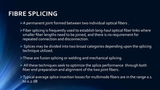


This document discusses different methods of fibre splicing used to join optical fibers, including fusion splicing, mechanical splicing, and array splicing. Fusion splicing involves heating the fiber ends and fusing them together, while mechanical splicing uses tubes, V-grooves, or other guides to hold the fibers in alignment without heating. Array splicing allows simultaneously splicing multiple fibers in a ribbon using techniques like electric arc fusion or V-groove chips. Average splice losses are typically 0.1 dB or less depending on the splicing technique and fiber type.


