Download to read offline
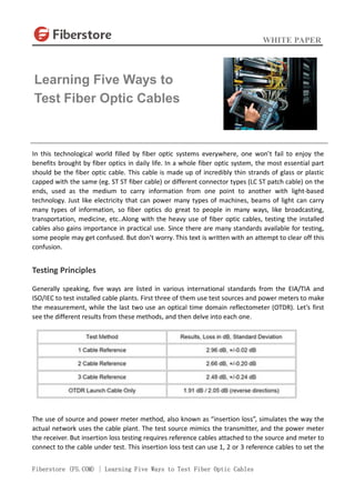


The document provides an overview of five methods for testing fiber optic cables, highlighting their significance in various applications such as broadcasting and medicine. It details the source and power meter method, which simulates actual network usage, and the optical time domain reflectometer (OTDR) method, used for measuring splice loss and cable damage. Additionally, the document explains how different reference cable configurations affect loss measurements in testing processes.