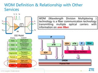
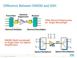
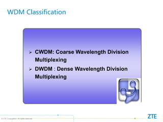
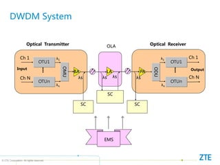
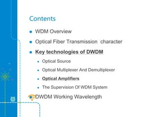
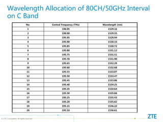
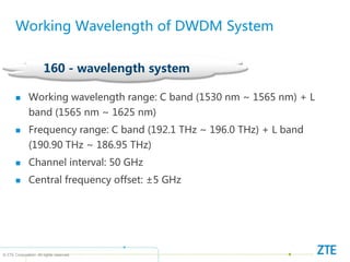
- DWDM technology transmits multiple optical carriers with information on one fiber, greatly saving fiber resources.
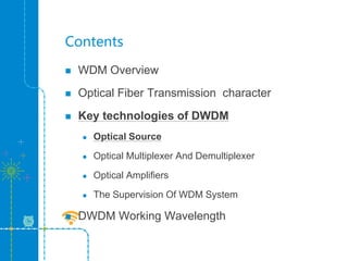
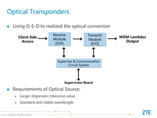
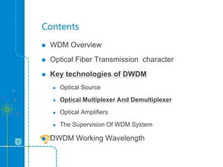
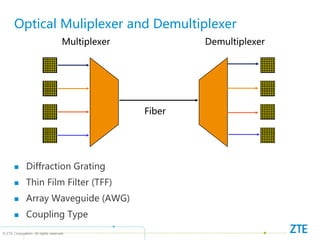
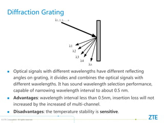
- Key technologies for DWDM include optical sources, multiplexers/demultiplexers, optical amplifiers, and supervision systems. Optical sources must have high dispersion tolerance while multiplexers use diffraction gratings, thin film filters, or arrayed waveguide gratings to combine/separate wavelengths.
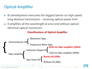
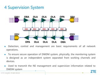
- Optical amplifiers and supervision systems are used to monitor signal quality during long-haul transmission, improving transmission efficiency and reliability.