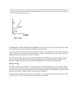
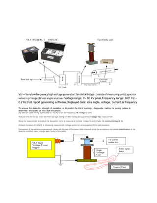
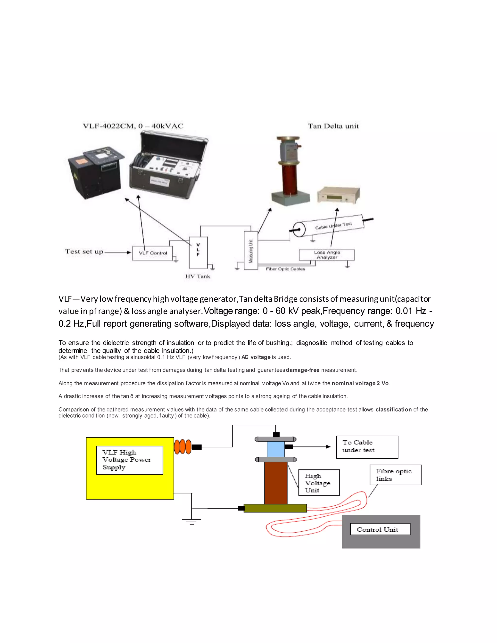
1) Tan delta testing uses a very low frequency AC voltage to measure the dissipation factor of insulation to determine its quality and condition. A higher loss angle indicates more contamination.
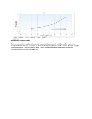
2) The cable or winding is disconnected and the test voltage is applied and increased in steps while tan delta measurements are taken. A straight trend line indicates healthy insulation while a rising line indicates contamination.
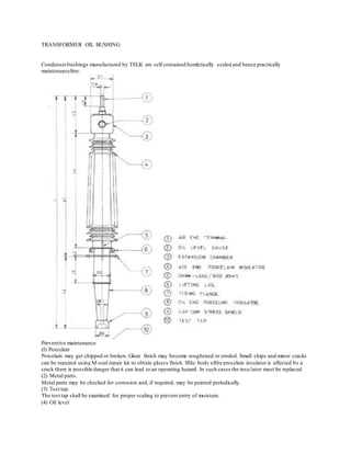
3) Routine maintenance of bushings includes inspecting the porcelain for cracks, metal parts for corrosion, oil levels, and cleaning surface contamination which can cause flashovers. Leaks should be repaired to prevent moisture issues.
![POWER TRANSFORMER TESTING
SPECIAL TESTS: -
1] Sweep Frequency Response Analysis (SFRA)
2] On Line Partial Discharge Test
3] Dielectric Response Measurement – by PDC or FDS technique.
4] Capacitance & Dissipation Factor ( Tan-Delta ) measurement.
5] 10KV Excitation Current Measurement
6] 10KV Turn Ratio Measurement
7] On Line Water Content Measurement
8] Transformer Oil Test – General Tests, DGA & FURAN
ROUTINE TESTS: -
1] Winding Resistance Measurement.
2] Insulation Resistance / Polarization Index.
3] Turns Ratio.
4] Voltage Ratio.
5] Open & Short Circuit.
6] Magnetic Balance.
7] Vector Group.
CT / PT Testing](https://image.slidesharecdn.com/testing-150707032023-lva1-app6891/85/Testing-2-320.jpg)
![1] Capacitance & Dissipation Factor ( Tan-Delta ) measurement..
2] Insulation Resistance / Polarization Index.
3] Polarity
4] Ratio
5] Primary Current Injection.
6] Knee Point Voltage Measurement.
CIRCUIT BREAKER TESTING
1] DCRM ( Dynamic Contact Resistance Measurement with Travel & Velocity)
2] CRM (Contact Resistance Measurement)
3] Timing Measurement Test.
4] Dew Point Measurement Test
5] Vidar Test for Vacuum Interrupter
4] Insulation Resistance
LIGHTENING ARRESSTORS ( L.A. ) TESTING
1] Capacitance & Dissipation Factor ( Tan-Delta ) measurement.
2] Insulation Resistance
3] On Line Leakage Current Measurement ( LCM )
H.T. MOTOR / GENERATOR TESTING
1] Capacitance & Dissipation Factor ( Tan-Delta ) measurement.
2] Insulation Resistance / Polarization Index.
3] Winding Resistance Measurement.
4] Partial Discharge Test.
5] Vibration & Current Signature Analysis.
6] Harmonic Analysis
7] Hi-Pot Test.
XLPE H.T. CABLE TESTING
1] Capacitance & Dissipation Factor ( Tan-Delta ) measurement.
2] VLF Hi-Pot Test
3] VLF Capacitance & Dissipation Factor ( Tan-Delta ) measurement.
4] VLF Partial Discharge Test
5] Insulation Resistance
6] D.C. Hi-Pot Test.
Ac hi-pot test--- portable 0.1 Hz VLF cable test
system for the testing of medium voltage cables.( output voltagesSinusoidal: 0 – 62 kV peak, 0 – 44 kV ef f ,DC:
± 0 - 60 kV](https://image.slidesharecdn.com/testing-150707032023-lva1-app6891/85/Testing-3-320.jpg)